

Page 1
TUB & SHOWER VALVE
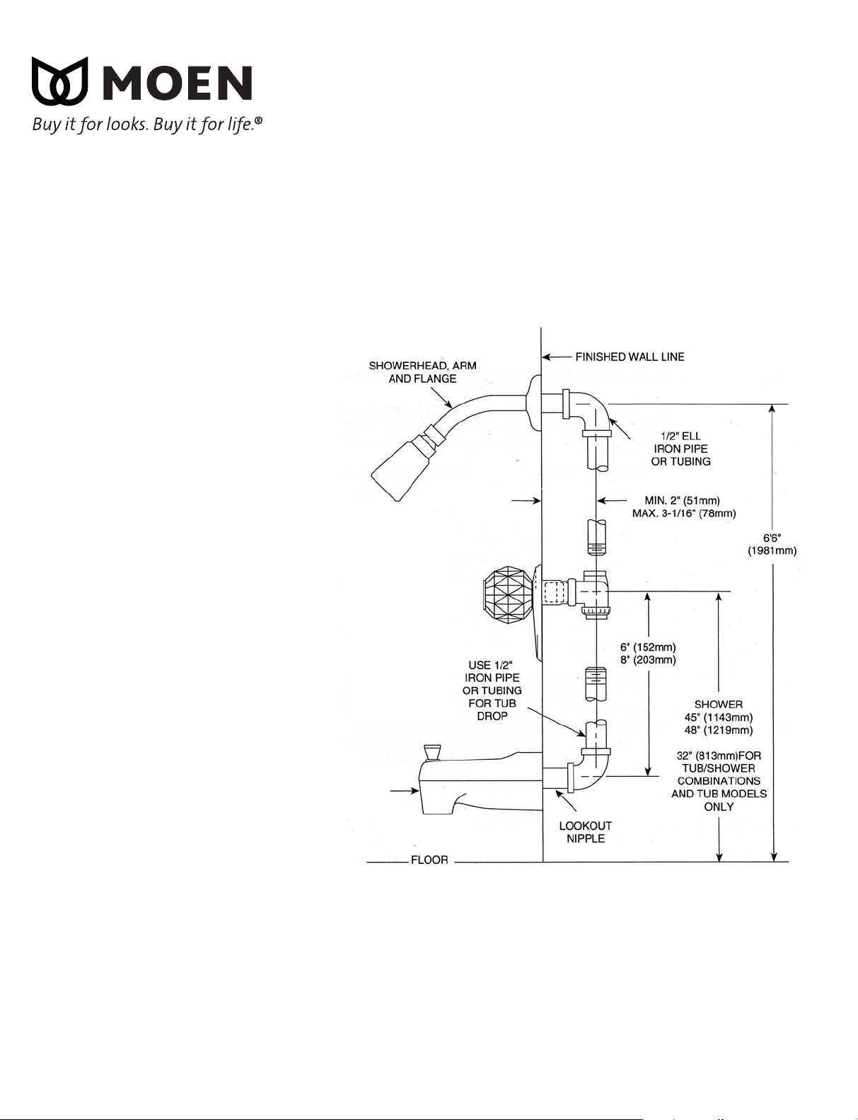
Measurements
These are shown on the drawings. The
depth measurment is critical. The center
line of the supply and discharge piping
should be a maximum of 3-1/16” (78mm)
and a minimum of 2” (51mm) behind the
finished wall surface, including tile. This is
1-1/16” (27mm) of adjustment.
MT302E
MODEL 72964 Series
INSTALLATION INSTRUCTIONS
THESE INSTRUCTIONS MUST BE
LEFT WITH HOMEOWNER
TWO HANDLE
Pipe, ells and nipples are not furnished
with the valve.
SPOUT
CAUTION:
Before turning water on during either rough-in or trim-out, make sure that cartridge retainer nuts are in place. The cartridges and
retainer nuts were probably installed and tested before leaving the factory. Although it is unlikely, it is nevertheless possible that
through the handling of the valve by any number of persons the retainer nuts may not be properly installed. This should be carefully checked at time of rough-in and trim-out. If the retainer nuts are not properly installed, water pressure could force the
cartridges out of the casting. Personal injury or water damage to the premises could result.
Always turn water off before disassembling the valve. Open both valve handles to
relieve water pressure and to insure that COMPLETE water shut-off has been accomplished.
Page 2

Flow
Director
Handle
Adapter
Cartridge
Valve
Body
Adapter
Nut
Washer
O-Ring
O-Ring
Cartridge
Nut
Escutcheon
Retainer
Escutcheon
Retainer
Escutcheon
Escutcheon
Escutcheon
Hub
Handle
Knob
Handle
Knob
Handle
Knob
Handle
Screw
Handle
Screw
Handle
Screw
Handle
Insert
Handle
Insert
Handle
Adapter
Cartridge
Nut
Wall
Tube
Model 62977
Only
Installation
2
1
2
1
This valve is designed for either CC or IPS connections, depending on the discretion of the installer. If
using the IPS connections, thread sealing tape should be used liberally on all threads.
Connect the valve to the supply lines by either means desired. The hot supply should be on the left, the
cold supply on the right.
Connect the shower riser pipe to the top outlet and the tub drop pipe to the bottom outlet. Make all
connections firm and tight. Block and secure all pipes to the inside wall.
Flow Director
For water supply lines plummed ceiling to floor, please follow these instructions:
Hold the valve with the valve connections in the down position as illustrated below. Use a large flat blade screwdriver and
remove the flow director, located in the center port, as illustrated. After removing the flow director, turn the valve over so
that the valve connections are in the up position, and reinstall the flow director.
Now the casting can be turned over, with the valve connections facing the ceiling, to accept ceiling-to-valve water supplies.
Trim
MAKE SURE ALL WATER SUPPLIES ARE OFF
SHOWER: Assemble shower arm flange to the long end of shower arm. Put thread seal tape on the threads at both
ends of the shower arm. Screw shower arm into ell inside wall, do not install showerhead at this time. When a pipe
lookout nipple is used, put thread seal tape on the pipe thread and screw the tub diverter spout into the lookout
nipple.
recommend the use of thread seal tape.
wrench is needed, use a small one with smooth jaws to grip spout end. Do NOT insert a tool into the spout end to
turn. You could damage the spout.
Flushing
IMPORTANT:
Pipe chips, sand, stones, and other solids found in new and renovated plumbing can damage the sealing
surface of the cartridge and cause a leak.
instructed below:
1. After installing and connecting your new faucet, install shower arm and tub spout, open both hot and cold cartridges.
2. Turn on both hot and cold water supply valves and allow the water to run from tub spout for 15 seconds.
3. Pull up on the diverter knob on the tub spout and run water through the shower riser for 15 seconds.
4. Turn off the hot and cold cartridges, install the showerhead and check the system for leaks.
* CAUTION: spout is ABS plastic and will crack upon contact with some pipe thread compounds. We
Pull out while turning so as not to scratch the wall. If a final turn by a
To avoid damage, DO NOT TURN ON THE SUPPLY VALVES until
MT302E
Page 3

Disassembly
Flow
Director
Handle
Adapter
Cartridge
Valve
Body
Adapter
Nut
Washer
O-Ring
O-Ring
Cartridge
Nut
Escutcheon
Retainer
Escutcheon
Retainer
Escutcheon
Escutcheon
Escutcheon
Hub
Handle
Knob
Handle
Knob
Handle
Knob
Handle
Screw
Handle
Screw
Handle
Screw
Handle
Insert
Handle
Insert
Handle
Adapter
Cartridge
Nut
Wall
Tube
Model 62977
Only
CAUTION: Turn OFF BOTH water supplies and open BOTH faucet handles to relieve water pressure and insure
that COMPLETE water shut-off has been accomplished.
FOR WALL TUBE MODELS: Pry off handle knob insert, if necessary. Remove handle screw, knob or tri-blade handle,
escutcheon, escutcheon retainer and then unscrew wall tube. Loosen the cartridge nut with an adjustable wrench and
remove it and the stem extension. Grasp the cartridge stem with pliers and pull it STRAIGHT out of the housing.
FOR HUB MODEL 62977: Pry off knob insert. Remove handle screw and pull off know handle. Remove hub (if it is covering the wrench flats on the cartridge nut) and loosen the cartridge nut with an adjustable wrench and remove it and the
handle adapter. Reassemble handle adapter, knob handle and screw to cartrige. Use handle to pull cartridge STRAIGHT
out of the housing.
Reassembly
CAUTION: Failure to follow these instructions might cause the cartridge to be damaged beyond repair.
Before installing cartridge, turn the stem to the ON position, waterway holes in the cartridge are lined up.
FOR WALL TUBE MODELS: Insert the cartridge STRAIGHT into the housing making sure that the lug on the cartridge is
engaged in the notch in the valve body. Place the stem extension over the cartridge stem and replace the cartridge nut,
START BY HAND, DO NOT CROSS THREAD, tighten the nut firmly with an adjustable wrench. Push on the wall tube, replace
escutcheon retainer and escutcheon. Replace handle parts.
FOR HUB MODEL 62977: Assemble the handle knob to the new cartridge using the handle adapters and tighten the handle
screw. This will aid in locating the cartridge properly in the valve body. Place the cartridge into the valve body and push
inward. Now push firmly while rotating handle knob counterclockwise. This will align the KEY on the cartridge with the
NOTCH in the valve body. When the key enters the notch, you will feel it drop in and the cartridge will be in place. To be certain, rotate the handle clockwise and then counterclockwise with gentle force. You should feel the handle knob stop in both
directions. If so, the cartridge is in place. Do not turn water on yet. Unscrew handle screw and remove handle knob in order
to replace the cartridge nut. Replace o-ring and nut, START BY HAND, DO NOT CROSS THREAD. Tighten the nut firmly with
an adjustable wrench. Replace handle parts. You are now ready to turn the water back on.
Page 4

All that is necessary to clean these faucets is to wipe them with a soft damp cloth such as terrycloth. Warm
water will remove dry water spots. CAUTION: do NOT use cleansers which contain abrasives or harsh
chemicals. NEVER use alcohol or other organic solvents. A high quality, non abrasive wax polish applied
occasionally, will help preserve the deep tones of the finish.
Cleaning and Care Instructions
for Special Finish Models
©2007 Moen Incorporated • 25300 Al Moen Drive • North Olmsted, OH 44070-8022 U.S.A.
In Canada Moen Inc. • 2816 Bristol Circle • Oakville, Ontario L6H 5S7
©2007 Moen Incorporated
MT302E - 4/07
Printed in U.S.A.
HELP LINE
Please do not return this product to the store.
If you need installation assistance, replacement parts or have questions regarding our warranty,
please call our Product Consultants at:
U.S.: 1-800-289-6636
Monday - Friday 8:00 a.m. to 8:00 p.m. EST
Saturday 8:00 a.m. to 6:30 p.m. EST
Or e-mail us at: moenwebmail@moen.com
Be sure to visit our website at www.moen.com
Canada 1-800-465-6130
Monday - Friday 7:30 a.m. to 5:00 p.m. EST
Or e-mail us at: cantsd@moen.com
Be sure to visit our website at www.moen.com
When ordering parts, specify finishes.
STOP
 Loading...