

Page 1
MODELS 4934 & 8983
TWO-HANDLE WIDESPREAD
LAVATORY FAUCET
INSTALLATION INSTRUCTIONS
THESE INSTRUCTIONS MUST BE
LEFT WITH HOMEOWNER
MT143B
Before turning water on during either rough-in or trim-out, make sure that the cartridge retainer nuts are in place. The cartridges
and retainer nuts were properly installed and tested before leaving the factor y. Although it is unlikely, it is nevertheless possible
that through the handling of the valve by any number of persons the car tridge retainer nuts may not be properly installed. This
should be carefully checked at time of rough-in and trim-out. If the retainer nuts are not properly installed, water pressure could
force the cartridge out of the casting. Personal injury or water damage to the premises could result.
Always turn water off before disassembling the valve. Open valve handle to releive water pressure and to insure that complete water shut-off has been accomplished.
CAUTION:
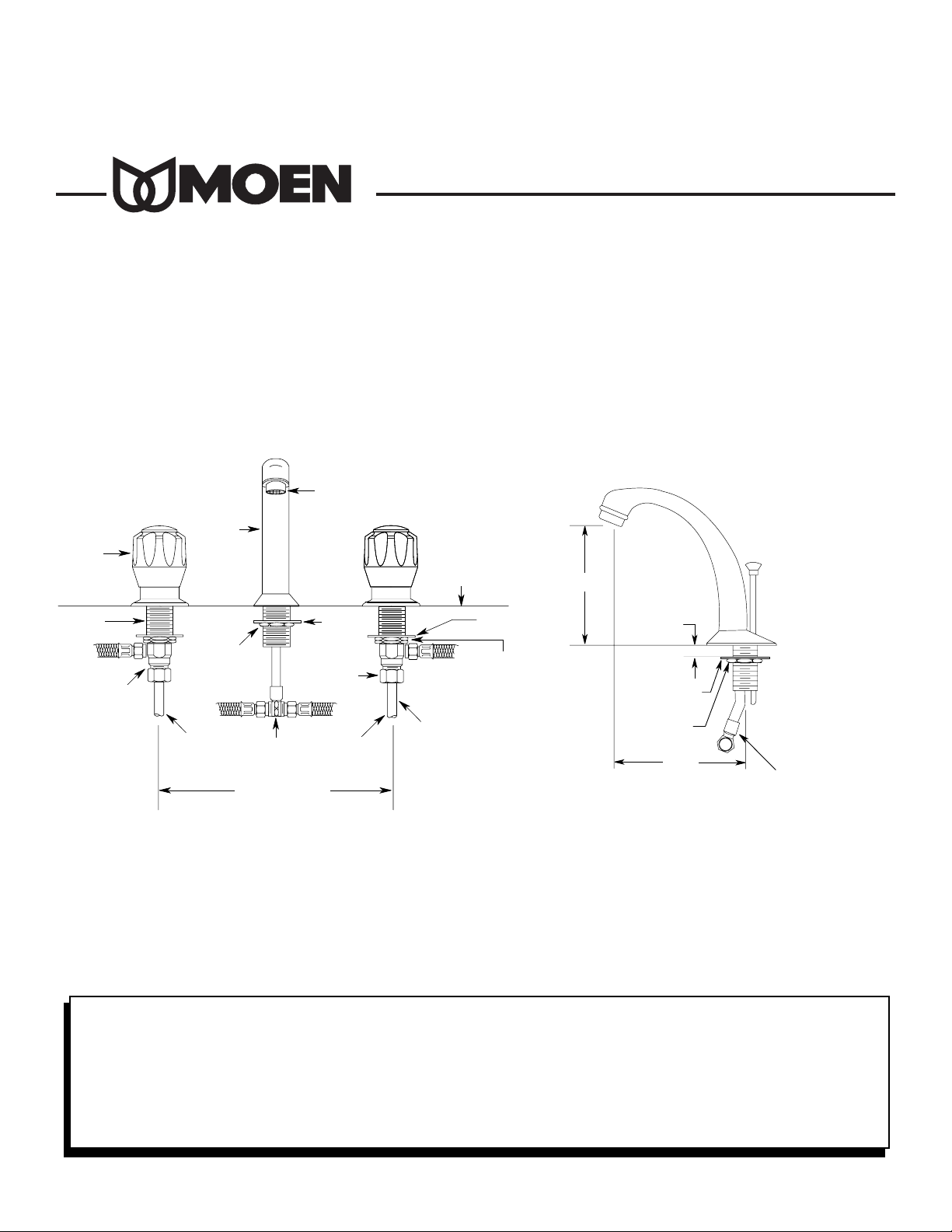
SPOUT INSTALLS THROUGH 1" MINIMUM DIAMETER HOLE.
VALVE INSTALLS THROUGH 1-1/8" MINIMUM DIAMETER HOLE.
Complies with ASME A112.18.1M and CSA B125
®
FLOW RATOR
AERATOR
HANDLE
KNOB
VALVE
BODY
1/2" NPT
THREADED
CONNECTIONS
SPOUT
SPOUT
MOUNTING
SPOUT
MOUNTING
NUT
HOT
SPOUT
UNION TEE
4" - 16" CENTERS
WASHER
TAILPIECE
NUT
COLD
DECK
MOUNTING
MOUNTING
WATER
SUPPLY LINES
(NOT FURNISHED)
WASHER
NUT
4-5/16"
1-1/4" MAX.
DECK
THICKNESS
WASHER
MOUNTING
NUT
5-1/8"
* SPOUT TUBE
(See note 5, Waste
Assembly Installation)
Page 2
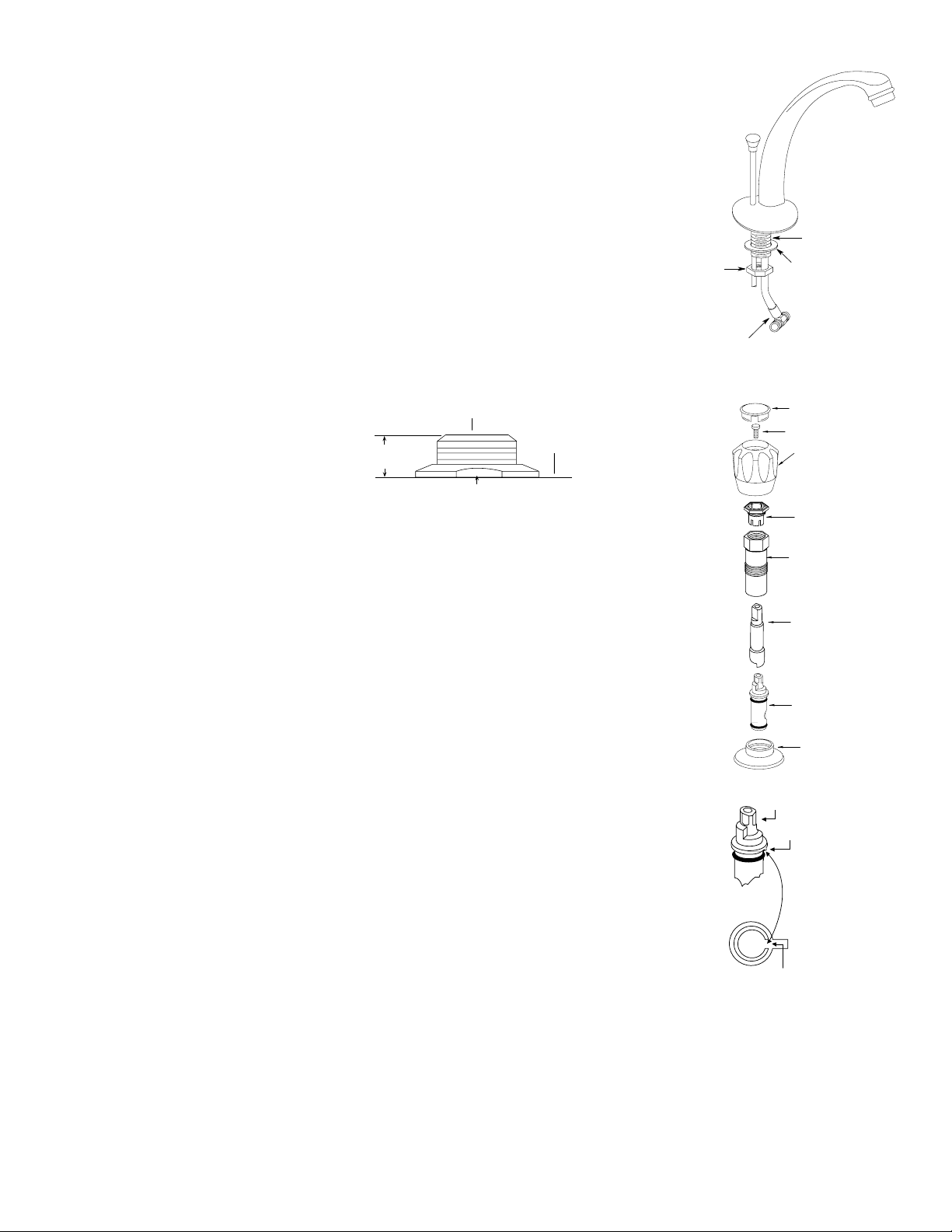
Disassembly
Installation Instructions
FOR LOCATING
CARTRIDGE PROPERLY
STEM
KEY
NOTCH
IN BODY
KNOB
INSERT
HANDLE
SCREW
HANDLE
KNOB
CARTRIDGE
NUT
STEM
GUIDE
STEM
EXTENSION
CARTRIDGE
ESCUTCHEON
* SPOUT TUBE
(SEE NOTE 5,
WASTE ASSEMBLY
INSTALLATION)
SPOUT
SHANK
MOUNTING
WASHER
MOUNTING
NUT
MT143B
Fill the recess under the valve and spout escutcheons with plumber's putty (not included). Place spout with escutcheon and adapter in place down through the center hole. Put washer over spout shank.Screw on mounting
nut and make hand-tight.Tur n mounting nuts on valve bodies all the way down, for basin clearance, and drop
on mounting washers.
With the valve bodies and supply tubing assembled under the sink, slide the bodies up through the holes.
Screw top mounting nuts down until top of valve bodies are 3/8" to 7/16" from top of deck. (See illustration).
Place a
3/8" bead of plumber's putty (not supplied) around the underside of handle escutcheons. Screw the escutcheons onto valve bodies and hand-tighten them until they bottom out.Screw the mounting nuts and washers up
against the bottom of the basin and hand-tighten. Hold the valve bodies from turning by using another wrench
on valve body flats.Install supply tubing to spout "T". Hold back spout tee with wrench when tightening supply tube.
Test the lift rod to make sure it operates freely. NOTE: If lift rod binds against spout union tee, carefully
bend spout tube slightly outward to clear lift rod.
Install handle knob onto stem extension. Install handle screw and tighten. Snap on handle inserts. Repeat with
the other knob.Make final tightening of all mounting nuts from below with a basin wrench.
Install waste assembly, see Lavatory Lift Rod and Waste Assembly then connect valve bodies to water supply
lines, do not turn on water at this time. Faucet flushing is required, see Flushing Instructions.
NOTE: to properly install handle
escutcheon and handle, valve bodies
must be above deck at dimensions shown.
IF HANDLE ROTATION IS REVERSED: TURN OFF WATER SUPPLIES AND OPEN HANDLES TO ALLEVI-
ATE PRESSURE. Remove handle, cartridge nut and upper handle adapter. Lift lower handle adapter and turn
180°, then reset on top of cartridge stem. Reinstall all components, making sure the cartridge nuts from both
sides are secure before turning water on, CAUTION: BE SURE NOT TO CROSS THREAD CARTRIDGE
NUTS DURING INSTALLATION.
CAUTION:Turn OFF BOTH water supplies, then open knobs to relieve pressure.
1. Remove handle knob insert and handle screw then lift off the handle knob.
2. Loosen the cartridge nut with an adjustable wrench and remove it and the stem guide as a unit together with the
stem extension.
3. Set aside the cartridge nut and stem guide and with the stem extension installed, reassemble handle knob, handle screw and tighten.
4. Grasp the handle knob and pull the cartridge STRAIGHT UP and out of the valve body.
1. Assemble the handle knob and the stem extension to teh new cartridge with the handle screw. Turn stem to
the ON position, waterway holes in cartridge are lined up.
2. Insert the cartr idge straight into the valve body.
3. Now press down firmly while rotating handle knob counterclockwise.This will align the "KEY" on the cartridge
with the "NOTCH" in the valve body.When the key enters the notch you will feel it drop in and the cartridge
will be in place.To be certain, rotate the handle clockwise and then counterclockwise with gentle force.You
should feel the handle knob stop in both directions.If so, the cartridge is in place. Do not turn the water on
yet.
4. Remove handle screw and handle knob. Install cartridge nut with stem guide over the stem extension, start
by hand DO NOT CROSS THREAD. Firmly tighten cartridge nut and stem guide using an adjustable wrench.
5. Replace handle parts. Turn on water supplies.
CAUTION: Failure to follow these instructions can cause a faulty installation or damage the
new cartridge.
Reassembly
Flushing Instructions
IMPORTANT: Pipe chips, sand, stones and other solids found in new and renovated plumbing can damage the sealing surfaces of the cartr idge and
cause a leak. To avoid damage, DO NOT TURN ON SUPPLY VALVES until instructed below.
1. After installing and connecting your new faucet, open both hot and cold cartridges.
2. Turn on both hot and cold water supply valves and allow the water to run for 15 seconds.
3. Turn off the hot and cold car tridges, unscrew the aerator from the end of the spout and clean any debris from the aerator screen.
4. Replace the aerator and check the system for leaks.
3/8" (10mm)
to 7/16" (11mm)
➤
➤
TOP OF VALVE BODY
DECK
MOUNTING NUT
Page 3

Lavatory Lift Rod and Waste Assembly
1. Thoroughly clean around drain opening in lavatory sink. Apply
1/4 inch bead of plumber's putty (not furnished) around the bottom side of seat.
2. Apply pipe joint compound or Teflon tape (not furnished) to top
threaded end of the drain body. Slip drain body up through the
drain opening and screw seat on the drain body.
3. Position the drain body with pivot rod opening extending rearward and tighten mounting nut until the drain body is snug.Wipe
excess plumber's putty from the seat area.Apply pipe joint compound (not furnished) to top threaded end of tailpipe and screw
into drain body. Tighten firmly by hand.
4. Position drain plug in either of the following ways:
A. VANDALPROOF - this design is to prevent unauthorized removal of the drain plug. Unscrew the pivot nut and remove the
pivot rod.Inside the drain body position the pivot rod through the
drain plug hole as shown in the illustration below.Screw the pivot
nut back on the drain body. DO NOT OVERTIGHTEN.
B. EASY REMOVAL - This design is for quick removal of drain
plug for cleaning. Just drop in the drain plug as shown in the
illustration below.
5. Install lift rod, with knob attached, into top of spout as shown.
Secure lift rod strap to bottom end of lift rod as shown.With pivot
rod in the down position, assemble strap to pivot rod using the
spring clip.The strap will have to be bent to reach the pivot rod
on some installations. Adjustment may be required so lift rod
clears spout tube and connection (i.e., bend spout tube outwards).
6. With the drain plug in full open position, adjust lift rod and knob
to clear faucet and tighten lift rod strap screw.
CAUTION: To avoid the lift rod
knob rubbing against spout, do
not install rod any lower than
dimension shown.
LIFT ROD
AND KNOB
SPOUT
VANDAL-
PROOF
HOLE
DRAIN
PLUG
2-1/8"
LIFT
ROD
STRAP
SCREW
LIFT
ROD
STRAP
1-1/2"
PIPE
JOINT
COMPOUND
OR
TEFLON
TAPE (NOT
FURNISHED)
SEAT
MAX. 2-1/2"
MIN. 1-1/2"
8"
MOUNTING
NUT
DRAIN
BODY
PIPE
JOINT
COMPOUND
OR
TEFLON
TAPE (NOT
FURNISHED)
1-1/4"
TAILPIECE
PIVOT
ROD SEAT
PIVOT
NUT
LIFT ROD
STRAP
SHOWN
IN BENT
POSITION
PIVOT
ROD
SPRING
CLIP
BOTTOM
GASKET
FLAT
WASHER
B. EASY REMOVAL
PIVOT
ROD
VANDALPROOF
POSITION
A.VANDALPROOF
POSITION FOR
EASY REMOVAL
PIVOT
ROD
FAUCET PARTS
CARTRIDGE
ESCUTCHEON
MOUNTING NUT
MOUNTING
WASHER
KNOB
INSERT
HANDLE
SCREW
HANDLE
KNOB
STEM
GUIDE
CARTRIDGE
NUT
STEM
EXTENSION
MOUNTING
NUT
SPOUT
UNION TEE
LIFT ROD
AND KNOB
FLOW RATOR
SPOUT
ASSEMBLY
SPOUT MOUNTING
WASHER
MOUNTING NUT
WATER
SUPPLY LINE
AERATOR
SPOUT
Page 4

Moen Incorporated 25300 Al Moen Drive, Nor th Olmsted, OH 44070-8022, U.S.A.
In Canada:
Moen Inc. 2816 Bristol Circle, Oakville, Ontario L6H5S7
MT143B SEP 95
© Copyright 1995
Moen Incorporated
Printed in U.S.A.
HELPLINE:
For answers to any product, installation,
replacment parts or warranty questions,
call our consumer helplines.
In the U.S., toll free:
1-800-321-6636
In Canada call:
Toronto, 905-829-3400
Rest of Canada, 1-800-465-6130
Consumer Information
Faucets made of leaded brass alloys may contribute small amounts of lead to water that is allowed to stand in contact with the brass. The amount of
lead contributed by any faucet is highest when the faucet is new.The following steps may reduce potential exposure to lead from faucets and other parts
of the plumbing system:
• Always run the water for a few seconds prior to use for drinking or cooking.
• Use only cold water for drinking or cooking.
• If you wish to flush the entire plumbing system of water that has been standing in the pipes or other fittings, run the cold water until the temperature
of the water drops, indicating water coming from the outside main.
• If you are concerned about lead in your water, have your water tested by a certified laboratory in your area.
®
 Loading...