

Moeller Marine XI-OC Signal Modules User Manual
Building Automation
Hardware and Engineering
XI/OC Signal Modules
05/02 AWB2725-1452GB
SystemsIndustrial Automation

All brand and product names are trademarks or registered
trademarks of the owner concerned.
st
published 2002, edition date 05/02
1
© Moeller GmbH, 53105 Bonn
Author: Peter Roersch
Editor: Thomas Kracht
Translator: Patrick Chadwick
All rights reserved, including those of the translation.
No part of this manual may be reproduced in any form
(printed, photocopy, microfilm or any otherprocess) or processed,
duplicated or distributed by means of electronic systems without
written permission of Moeller GmbH, Bonn.
Subject to alteration without notice.

Warning!
Dangerous electrical voltage!
Before commencing the installation
• Disconnect the power supply of the device.
• Ensure that devices cannot be accidentally restarted.
• Verify isolation from the supply.
• Earth and short circuit.
• Cover or enclose neighbouring units that are live.
• Follow the engineering instructions (AWA) of the
device concerned.
• Only suitably qualified personnel in accordance with
EN 50110-1/-2 (VDE 0105 Part 100) may work on
this device/system.
• Before installation and before touching the device ensure
that you are free of electrostatic charge.
• The functional earth (FE) must be connected to the protective
earth (PE) or to the potential equalisation. The system installer
is responsible for implementing this connection.
• Connecting cables and signal lines should be installed so
that inductive or capacitive interference does not impair the
automation functions.
• Install automation devices and related operating elements in
such a way that they are well protected against unintentional
operation.
• Suitable safety hardware and software measures should be
implemented for the I/O interface so that a line or wire
breakage on the signal side does not result in undefined
states in the automation devices.
• Ensure a reliable electrical isolation of the low voltage for the
24 volt supply. Only use power supply units complying with
IEC 60364-4-41 (VDE 0100 Part 410) or HD 384.4.41 S2.
• Deviations of the mains voltage from the rated value must
not exceed the tolerance limits given in the specifications,
otherwise this may cause malfunction and dangerous
operation.
• Emergency stop devices complying with IEC/EN 60204-1 must
be effective in all operating modes of the automation devices.
Unlatching the emergency-stop devices must not cause restart.
• Devices that are designed for mounting in housings or control
cabinets must only be operated and controlled after they have
been installed with the housing closed. Desktop or portable
units must only be operated and controlled in enclosed
housings.
• Measures should be taken to ensure the proper restart of
programs interrupted after a voltage dip or failure. This should
not cause dangerous operating states even for a short time.
If necessary, emergency-stop devices should be implemented.
• Wherever faults in the automation system may cause
damage to persons or property, external measures must be
implemented to ensure a safe operating state in the event of
a fault or malfunction (for example, by means of separate limit
switches, mechanical interlocks etc.).
Moeller GmbH
Safety instructions
I

05/02 AWB2725-1452GB
Contents
About this Manual 3
Additional manuals 3
Intended users 3
Abbreviations and symbols 3
1 Signal modules 5
Overview 5
Accessories 6
Assembly 6
PLC connection 6
Slot assignment in the module racks 7
Mounting the module rack 8
– Mounting on the top hat rail 8
– Mounting on the mounting plate 8
Detaching the module rack 8
Mounting the signal modules 10
Detaching the signal modules 10
Fixing the terminal block 10
Wiring up the I/O signals 11
– Wiring up the screw terminal block 11
– Wiring up the spring-loaded terminal block 11
Wiring the digital input module (24 V DC) 11
Wiring up the digital output module (24 V DC) 12
– Wiring up the relay output module 12
– Wiring up the transistor output module 12
Wiring up the analogue module 13
Project planning 13
Dimensions 13
– Signal modules 13
– Module rack 13
2 Temperature acquisition module XIOC-4T-PT 15
Features 15
Wiring 15
Data evaluation 16
– Range 1: –50 to +400 °C (Pt100/Pt1000) 16
– Range 2: –20 to +40 °C (Pt100) 17
Conversion tables 17
Fault-finding 19
– Faults that affect a single channel 19
– Faults that affect more than one channel 19
3 Counter module 21
Wiring of the counter module 21
– Connect the incremental encoder to the counter input 21
– Connecting third-party equipment to the
comparator output 22
1

Contents
05/02 AWB2725-1452GB
4 Te chni cal data 23
XControl 23
Digital input modules 24
Digital output modules 25
– Transistor output modules 25
– Relay output module 26
Analogue input modules 27
Analogue output module 28
Temperature acquisition module 30
Counter module 31
– Mode (operating mode) switch 32
General technical data for the counter 34
Index 35
2
05/02 AWB2725-1452GB
About this Manual
This manual describes the XIOC signal modules for the expandable
PLC types XC-CPU100/200/400/600. In Chapter 1 you will find
information on mounting and wiring, which is applicable to all the
signal modules. Chapter 4 provides comprehensive technical data.
This chapter also starts with a general section. Specific features are
then dealt with separately or, there where it is more useful,
combined in groups. Chapter 2 and Chapter 3 include further
detailed information on the temperature acquisition module and
the counter module.
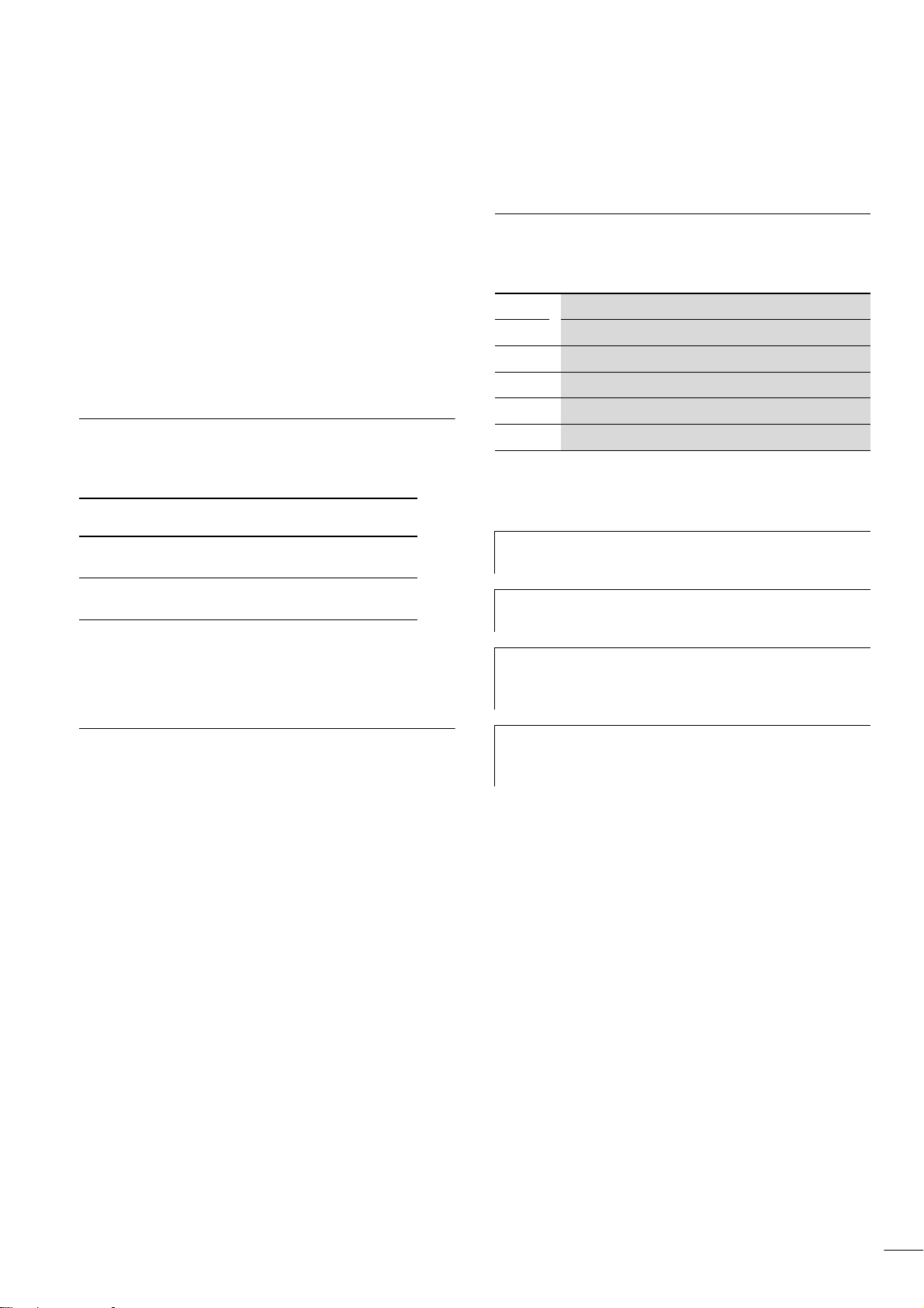
Additional manuals
The PLC types that are used in conjunction with the signal modules
are described in the following manuals:
PLC type Manual no. Article no.
XC-CPU100/200
XC-CPU400/600
These manuals are also available online as PDF files, under
“www.moeller.net l support”. Enter the manual number here as
the search text.
AWB27241453GB
AWB27001428GB
Abbreviations and symbols
The abbreviations and symbols used in this manual have the
following meanings:
I/O Input/Output
PLC
I
o
I
1
U
o
U
1
All dimensions are in millimetres, unless otherwise specified.
X Indicates instructions on what to do
h
h
i
Programmable Logic Controller
Input current
Output current
Input voltage
Output voltage
Draws your attention to interesting tips and
supplementary information
Important!
Indicates the risk of minor material damage.
Caution!
Indicates the risk of major damage to property, or slight
injury.
Intended users
Read this manual carefully, before you install the signal module
and start using it. We assume that you are familiar with basic
physical concepts and are experienced in reading technical
drawings and dealing with electrical equipment.
Warning!
j
Indicates the risk of major damage to property, or serious
or fatal injury.
For greater clarity, the chapter title is shown at the top left of the
page, and the current section at top right. Exceptions are the first
page of each chapter, and empty pages at the end.
3

05/02 AWB2725-1452GB
4

05/02 AWB2725-1452GB
1 Signal modules
Overview
• Digital input/output modules
• Analogue input/output modules
The signal modules for the expandable PLC types XC-CPU100/
• Function modules, such as counter and network modules
200/400/600 are divided into:
The following table provides an overview of the modules.
Table 1: List of signal modules
Designation
Module rack XIOC-BP-XC For CPU with power supply
Digital input module XIOC-8DI 8 channels, 24 V DC
Digital output module XIOC-8DO 8 channels, transistor output 12/24 V DC (source type)
Analogue input module XIOC-8AI-I2 Current input (channels 0 to 7) 4 to 20 mA, 12 bit
Analogue output module XIOC-2AO-U1-2AO-I2 Voltage output (channel 0 + 1) 0 to 10 V DC,
Counter module XIOC-1CNT-100kHz Input for fast counter, maximum frequency 100 kHz, 1 channel, switchable 1/2-phase,
1) With short-circuit protection
Type Technical data
XIOC-BP-XC1 For CPU with power supply, 1 signal module
XIOC-BP-2 For 2 signal modules
XIOC-BP-3 For 3 signal modules
XIOC-16DI 16 channels, 24 V DC
XIOC-16DI-AC 16 channels, 200 to 240 V AC
XIOC-16DO 16 channels, transistor output 12/24 V DC (source type)
XIOC-16DO-S
XIOC-12DO-R 12 channels, relay output
XIOC-8AI-U1 Voltage input (channels 0 to 7) 0 to 10 V DC,12 bit
XIOC-8AI-U2 Voltage input (channels 0 to 7) –10 to +10 V DC,12 bit
XIOC-4T-PT Pt100/1000 input (channels 0 to 3) 15 bit, signed
XIOC-2AO-U2 Voltage output (channel 0 + 1) –10 to 10 V DC
XIOC-4AO-U2 Voltage output (channels 0 to 4) –10 to 10 V DC
XIOC-4AO-U1 Voltage output (channels 0 to 4) 0 to 10 V DC
XIOC-2CNT-100kHz Input for fast counter, maximum frequency 100 kHz, 2 channels, switchable 1/2-phase,
1)
16 channels, transistor output 12/24 V DC (source type)
current output (channel 2 + 3) 4 to 20 mA, 12 bit
2 open-collector outputs
2 open-collector outputs per channel
5
Signal modules
05/02 AWB2725-1452GB
Accessories
Designation Type Comments
Spring-loaded
terminal
Screw terminals
XIOC-TERM-18T For digital and analogue
I/O modules
XIOC-TERM-18S
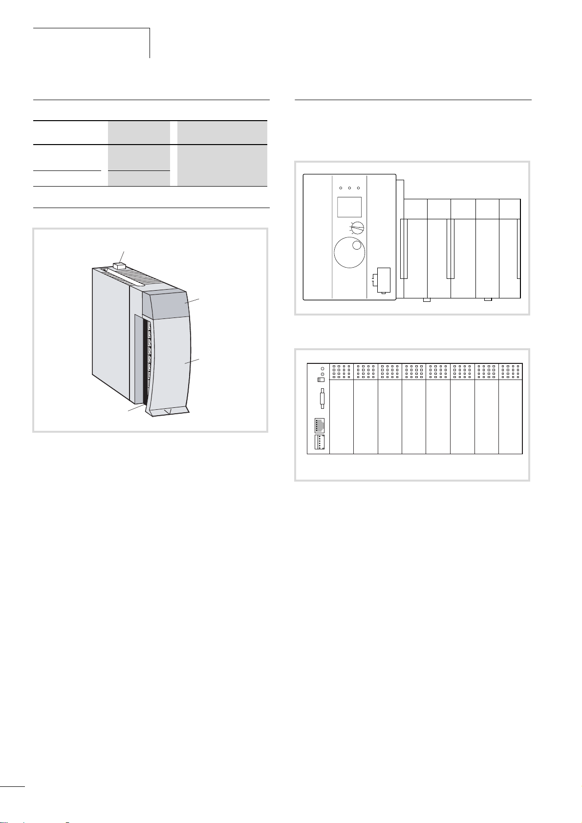
Assembly
a
0 1 2 3
4 5 6 7
8 9 10 11
12 13 14 15
b
c
PLC connection
The XIOC modules are the I/O modules for the PLC types
XC-CPU100/200/400/600. The following diagrams show the
assembly of XIOC modules connected to a PLC.
Figure 2: XC-CPU400/600 with XIOC signal modules
d
Figure 1: Assembly of a signal module
a Catch
b LED display
c I/O cover
d Terminal block
Figure 3: XC-CPU100/200 with XIOC signal modules
6
05/02 AWB2725-1452GB
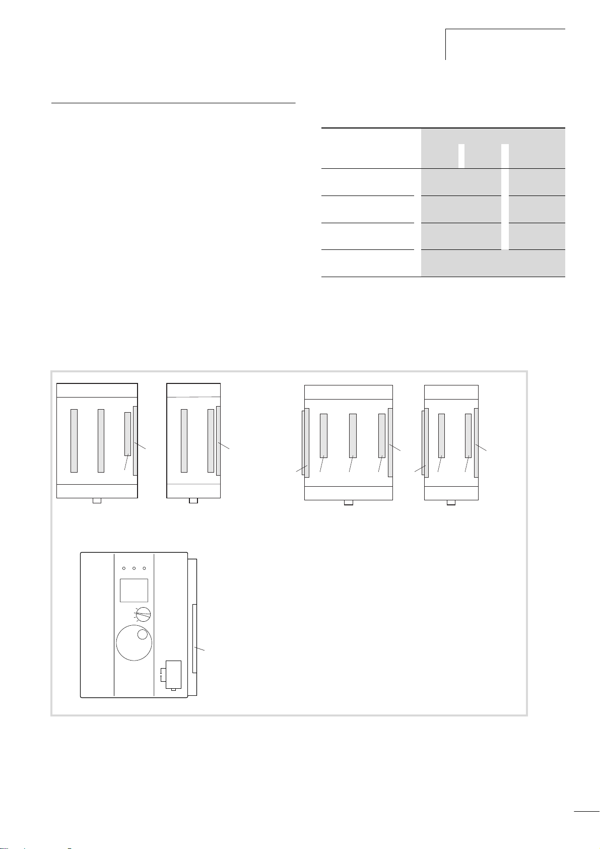
Slot assignment in the module racks
Slot assignment in the module rack s
The XIOC modules are plugged onto module racks that provide the
connection to the PLC. The modules are also interconnected
through the module rack.
The integrated bus system ensures interference-free transmission
between the individual slots on the bus. In addition, the bus
system supplies the individual modules with the voltage that is
required for internal signal processing.
The supply voltage for the I/O electronics is applied directly to the
corresponding I/O modules.
Four different module racks are available:
XIOC-BP-XC1 XIOC-BP-XC
Table 2: Slot assignment in the module racks
Module rack Slots
1 2 3
XIOC-BP-XC
(Basic module rack)
XIOC-BP-XC1
(Basic module rack)
XIOC-BP-2
(Expansion module rack)
XIOC-BP-3
(Expansion module rack)
CPU with power
supply
CPU with power
supply
I/O module –
I/O module
–
I/O module
As a rule, the first module rack, which is used to take the CPU type
XC-CPU100/200, is a basic module rack. You can add on several
expansion module racks to the right side. The module racks must
be arranged so that one CPU module and a maximum of 7 XIOC
signal modules can be planned (a fig. 4).
XIOC-BP-3 XIOC-BP-2
d
adba
XC400/XC600
bc
d
d
ee
Figure 4: top left: expandable basic module rack
bottom left: expandable XC-CPU400/600
top right: expansion module rack
a Slot 1
b Slot 2
c Slot 3
d Bus expansion connector (socket)
e Bus expansion connector (plug)
bc
adba
7

Signal modules
05/02 AWB2725-1452GB
Mounting the module rack
The module rack can either be snapped onto a top hat (DIN) rail,
or screwed directly onto the mounting plate.
Caution!
i
The expansion module rack must only be plugged in or
pulled out when the power is switched off. FIrst detach
the CPU or I/O modules that were plugged into the
module rack. Discharge yourself from any electrostatic
charge before touching electronic modules. Voltage peaks
on the bus connector may cause malfunction or damage
to the modules.
Read the manual AWB2700-1428D for information on
h
mounting the XC-CPU400/600, and manual
AWB2724-1453D for the XC-CPU100/200.
Mounting on the top hat rail
X Use a screwdriver to pull out the locking bar until the catch
snaps into position. The locking bar is then held in this
position .
X Place the module rack on the top hat mounting rail so that the
1
top edge of the rail fits into the slot, and then slide the module
rack into the correct position .
X Press down the catch of the locking bar. The bar snaps in behind
2
the edge of the mounting rail. Check that the module rack is
firmly seated .
X If you want to fit an expansion module rack: push it to the left,
3
until the bus connector of the expansion module rack can be
plugged into the bus connector socket of the XC-CPU400/600
or the basic or expansion module rack. Take care that the bus
connectors of the module racks are completely engaged, in
order to ensure reliable electrical contact.
Mounting on the mounting plate
The spring contacts that protrude from the back of the module
rack are intended to provide a ground for the modules. They must
have a reliable electrical contact with the mounting plate.
Take care that the contact areas are protected from corrosion and
– if you are using painted mounting plates – that the paint layer is
removed from the contact areas.
X Plug the bus connector of the expansion module rack into the
bus connector of the XC-CPU400/600 or the basic or expansion
module rack. Take care that the bus connectors of the module
racks are completely engaged, in order to ensure reliable
electrical contact.
Detaching the module rack
X Use a screwdriver to pull out the locking bar until the catch
snaps into position. The locking bar is then held in this
position .
X Only with expansion module racks: Slide the expansion module
1
rack along the top hat rail to the right, until the bus connectors
are disengaged.
X Take the module rack off the rail.
8
05/02 AWB2725-1452GB
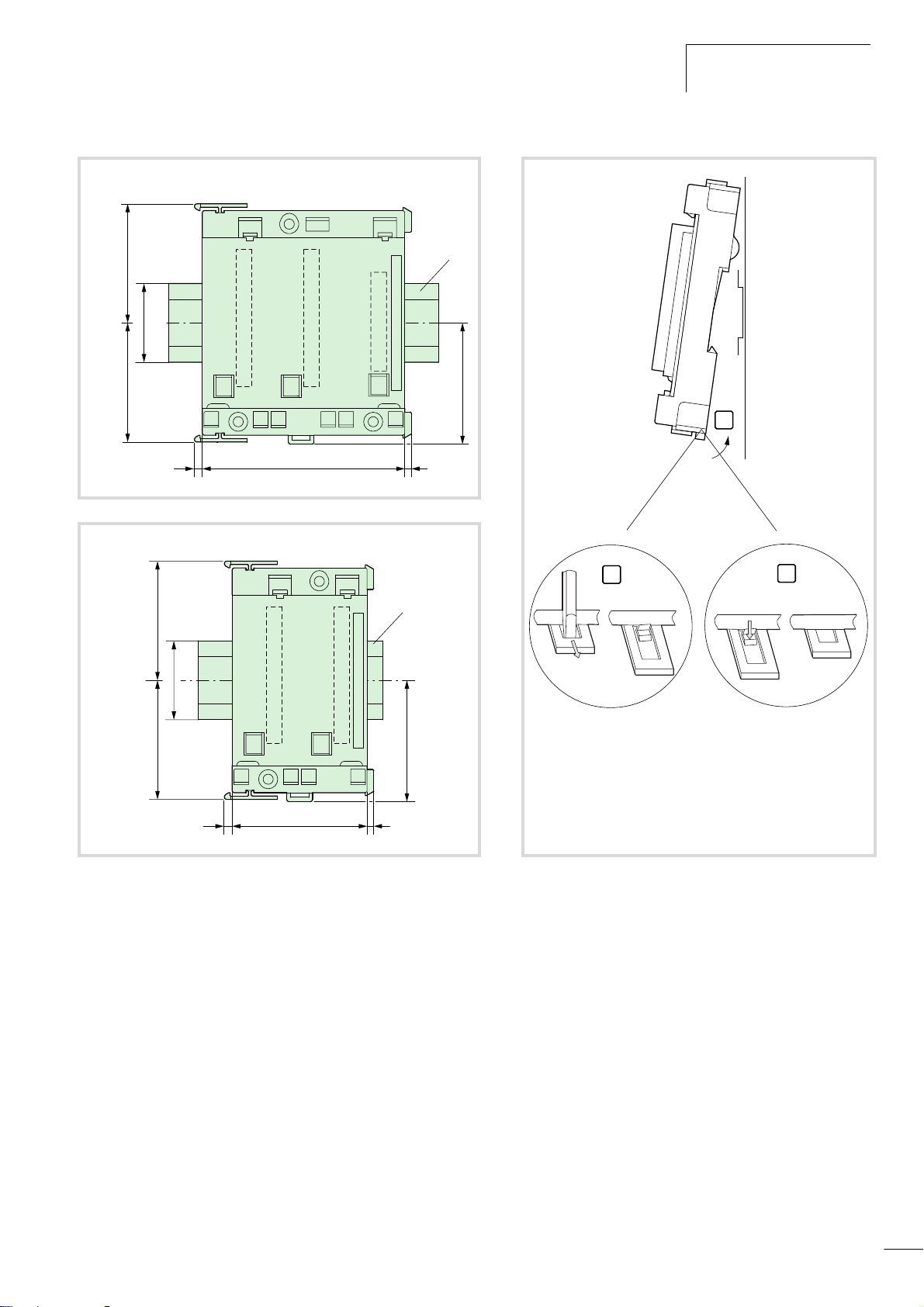
35
Detaching the module rack
a
53.5 53.5
3.5 390
53.5
35
53.5
3.5 360
a
54.5
54.5
2
1
3
Figure 5: Mounting on a 35 mm top hat (DIN) rail,
top left: XIOC-BP-XC1, (XIOC-BP-3)
bottom left: XIOC-BP-XC, (XIOC-BP-2)
a 35 mm top hat rail
See also dimensions on Page 14.
9
 Loading...