

Moeller Marine XControl PLC System User Manual

Hardware, Engineering and Function Description
XControl PLC System
XC-POW50(-XION)-UPS Base Module
XC-ADP(-XION) Power Supply Module
XC-NET-CAN CANopen Module
XC-NET-DP-M PROFIBUS-DP Module
XC-CPU601-E.M CPU Module
XC-SYS1 Operator Module
12/01 AWB2700-1428GB
1st edition 2001, edition date 12/01
© Moeller GmbH, Bonn
Author: Peter Roersch
Editor: Thomas Kracht
Translator: Terence Osborn
All brand and product names are trademarks or registered
trademarks of the owner concerned.
All rights reserved, including those of the translation.
No part of this manual may be reproduced in any form
(printed, photocopy, microfilm or any otherprocess) or processed,
duplicated or distributed by means of electronic systems without
written permission of Moeller GmbH, Bonn.
Subject to alterations without notice.

Warning!
Dangerous electrical voltage!
Before commencing the installation
• Disconnect the power supply of the device.
• Ensure that devices cannot be accidentally restarted.
• Verify isolation from the supply.
• Earth and short circuit.
• Cover or enclose neighbouring units that are live.
• Follow the engineering instructions (AWA) of the
device concerned.
• Only suitably qualified personnel in accordance with
EN 50110-1/-2 (VDE 0105 Part 100) may work on
this device/system.
• Before installation and before touching the device ensure
that you are free of electrostatic charge.
• The functional earth (FE) must be connected to the protective
earth (PE) or to the potential equalisation. The system installer
is responsible for implementing this connection.
• Connecting cables and signal lines should be installed so
that inductive or capacitive interference do not impair the
automation functions.
• Install automation devices and related operating elements in
such a way that they are well protected against unintentional
operation.
• Suitable safety hardware and software measures should be
implemented for the I/O interface so that a line or wire
breakage on the signal side does not result in undefined
states in the automation devices.
• Ensure a reliable electrical isolation of the low voltage for the
24 volt supply. Only use power supply units complying with
IEC 60364-4-41 (VDE 0100 Part 410) or HD 384.4.41 S2.
• Deviations of the mains voltage from the rated value must
not exceed the tolerance limits given in the specifications,
otherwise this may cause malfunction and dangerous
operation.
• Emergency stop devices complying with IEC/EN 60204-1 must
be effective in all operating modes of the automation devices.
Unlatching the emergency-stop devices must not cause restart.
• Devices that are designed for mounting in housings or control
cabinets must only be operated and controlled after they have
been installed with the housing closed. Desktop or portable
units must only be operated and controlled in enclosed
housings.
• Measures should be taken to ensure the proper restart of
programs interrupted after a voltage dip or failure. This should
not cause dangerous operating states even for a short time.
If necessary, emergency-stop devices should be implemented.
• Wherever faults in the automation system may cause
damage to persons or property, external measures must be
implemented to ensure a safe operating state in the event of
a fault or malfunction (for example, by means of separate limit
switches, mechanical interlocks etc.).
Moeller GmbH
Safety instructions
I

12/01 AWB2700-1428GB
Contents
About This Manual 3
Structure 3
Abbreviations and symbols 3
1 Hardware and Engineering 5
Setup 5
Mounting 6
– Fitting/removing modules 6
– Fitting XI/ON base modules 8
Engineering 8
– Control cabinet design 8
– Ventilation 9
– Device arrangement 9
– Preventing interference 9
– Suppression of interference sources 9
– Shielding 9
– Lightning protection measures 9
Wiring example (overview) 10
Switching the power supply on/off 10
XC-ADP/XC-ADP-XION base modules 11
– General 11
– Task of the XC-ADP-XION module 11
– Task of the XC-ADP module 11
– Engineering the XC-ADP-XION base module 11
– Expansion with XI/ON modules 12
XC-POW50-UPS/XC-POW50-XION-UPS
power supply modules 12
– General 12
–Task 12
– Setup 12
– Engineering 12
XC-NET-DP-M PROFIBUS-DP module 12
– General 12
–Task 12
– Engineering 13
– Bus terminating resistors 14
XC-NET-CAN CANopen module 14
– General 14
– Task of the module 14
– Engineering 14
XC-SYS1 operator module 16
–Task 16
– Setup 16
XC-CPU601-E.M processor 17
–Task 17
– Setup 17
2 Establishing the Connection Between PC and XC600 19
Requirements of the Ethernet module in the PC 19
Configuring the Ethernet module 19
Configuring the XC600 20
Creating the connection between PC and XC600 20
1

Contents
12/01 AWB2700-1428GB
3 Creating an Example Project 23
Setting the target system 24
Configuring the XC600 controller 25
– Creating programs 27
PROFIBUS-DP expansion 28
– Adding a PROFIBUS-DP module
to the XC600 controller 28
– Adding a remote XI/ON gateway 28
– Creating a program for PROFIBUS-DP expansion 29
CANopen bus expansion 30
– Adding a CANopenmodule to the XC600 controller 30
– Creating a program for remote outputs
on the CANopen bus 32
4 Functions of the Operator Module 33
Initial PLC startup 33
Loading the program into the PLC 33
Starting up the PLC with a bootable and
activated program 34
Entering parameters or status modifications 34
Starting programs 35
Display programs on the hard disk (internal) and
on the CompactFlash card (external) 35
Startup with configuration scan 36
Error and event messages 36
General messages 37
– Deleting programs from the hard disk 37
Deleting programs from the working memory 37
– Reset function (initialisation of variables) 37
Handling several programs 38
Deleting programs 38
Copying programs 38
Editing programs on the CompactFlash card (CFC) 38
Password 39
Displaying text from the user program 39
– Shutting down the system 40
Switching off the power supply 40
5 Menu Overview of the Operator Module 41
Basic menu 42
– MAIN MENU 42
Appendix 47
Other error messages 47
Technical Data 48
Index 51
2
12/01 AWB2700-1428GB
About This Manual
Structure
The XC600 PLC is designed for the control of machines and
systems. This controller provides the basis for an extensive PLC
system using interfaces for the standard networks PROFIBUS-DP,
CANopen and ETHERNET, for connecting remote expansion
modules and intelligent devices.
The documentation for the PLC is divided into five sections:
• Hardware and engineering
• PC-XC600 connection
• Creating an example project
• Functions of the operator modules
• Menu overview of the operator module
The Chapter “Hardware and Engineering” provides information
on the installation and engineering of the PLC as well as on the
possible PLC settings.
In order to communicate with the PLC, the PC must be connected
to it via the Ethernet network. The configuration of the Ethernet
module and the XC600 is described in the Chapter “Creating the
connection between PC and XC600” from Page 20.
Use of the XSoft software is then explained using a simple
example. This will show you how to configure and program the
controller. After you have downloaded the project you can then
test it as described in a Chapter “Creating an Example Project”
on Page 23.
Abbreviations and symbols
The abbreviations and symbols used in this manual have the
following meaning:
MSS
OMS
X Indicates instructions on what to do
”Choose Online r Login” means: Activate the Login menu item in
the Online menu.
Except for the first page of chapters and empty pages at the end,
the top left of the page shows the chapter title and the top right
of the page shows the current section for greater clarity.
Menu selector switch
Operating mode selector switch
Important!
Indicates the possibility of minor material damage.
Caution!
Indicates the possibility of major damage to property or
slight injury.
Warning!
Indicates the possibility of major damage to property or
serious or fatal injury.
The program can be started or stopped via the PLC's operator
module. These functions, as well as how to use the operator
module, are described in the Chapter “Functions of the Operator
Module” from Page 33 .
Chapter “Menu Overview of the Operator Module” from Page 41
explains the structure of all the menus and the individual menu
items.
3

12/01 AWB2700-1428GB
4
12/01 AWB2700-1428GB
1 Hardware and Engineering
Setup
The XC600 PLC has a modular design. The basic unit consisting of
the base, power supply, CPU and operator modules can be
expanded with function modules for communication. Modules for
the standard PROFIBUS-DP and CANopen networks are therefore
provided for this purpose. They provide the controller with access
to the I/O devices that log process data signals and control
actuators.
The process signals can also be connected locally with XI/ON input
and output modules. This requires the use of the power supply
module with the integrated XI/ON interface and the base module
with the XI/ON adapter.
A module consists of a circuit board that is embedded in a frame.
The special frame design makes it possible to stack the modules
together, thus allowing compact functional units to be combined
to suit the requirements of the task at hand.
The circuit boards of the individual function modules meet the
requirements of the PC/104+ specification. In addition to dimensions, the specifications also stipulate the requirements of the
PC/104+ bus that connects the modules. This bus also carries the
power supplies from the power supply module to the individual
function modules.
A configuration containing XI/ON input/output modules must
always include theXC-ADP-XION base module with the
XC-POW50-XION-UPS power supply module. The power supply
module adapts the PC/104+ bus to the XI/ON module bus using
the XI/ON interface. This bus is connected out from the base
module. The adapter on the base module provides the interface to
the XI/ON modules. The 24 V DC field power supply of the XI/ON
modules is also connected to the base module.
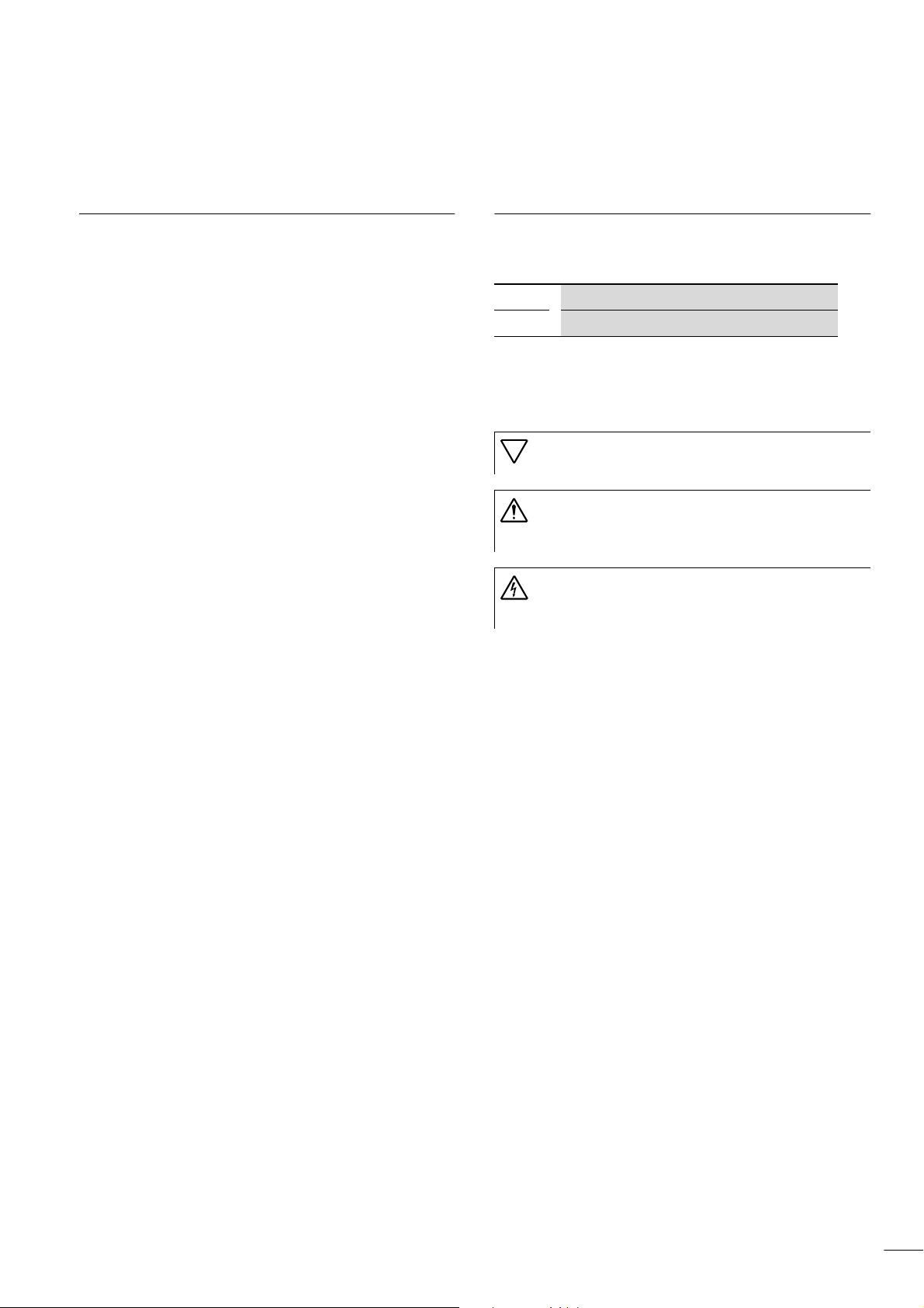
XC600 Base module Power supply
module
Without XI/ON
connection
With XI/ON connection XC-ADP-XION XC-POW50-XION-UPS
XC-ADP XC-POW50-UPS
c d e f g b a
Figure 1: Order of modules
a XC-ADP/XC-ADP-XION base module
b XC-POW50-UPS/XC-POW50-XION-UPS power supply module
c, d, e XC-NET-DP-M PROFIBUS-DP module*
or XC-NET-CAN CANopen module *
f XC-CPU601-ExM CPU module*
g XC-SYS1 operator module*
* Function modules
5
Hardware and Engineering
A maximum of three bus modules for PROFIBUS-DP and CANopen
can be fitted between the power supply and CPU module.
12/01 AWB2700-1428GB
Modules for the basic configuration: a, b, f, g
Bus modules: c, d, e
Mounting
Caution!
Only remove or fit modules with the power supply
switched off. Discharge yourself on any electrostatic
charge before touching a module.
Voltage peaks on the bus connector may cause
malfunctions or damage to the module.
The modules are supplied separately and must be fitted together.
Observe the order shown in Figure 1 and fit the base module first
of all on a horizontal mounting rail.
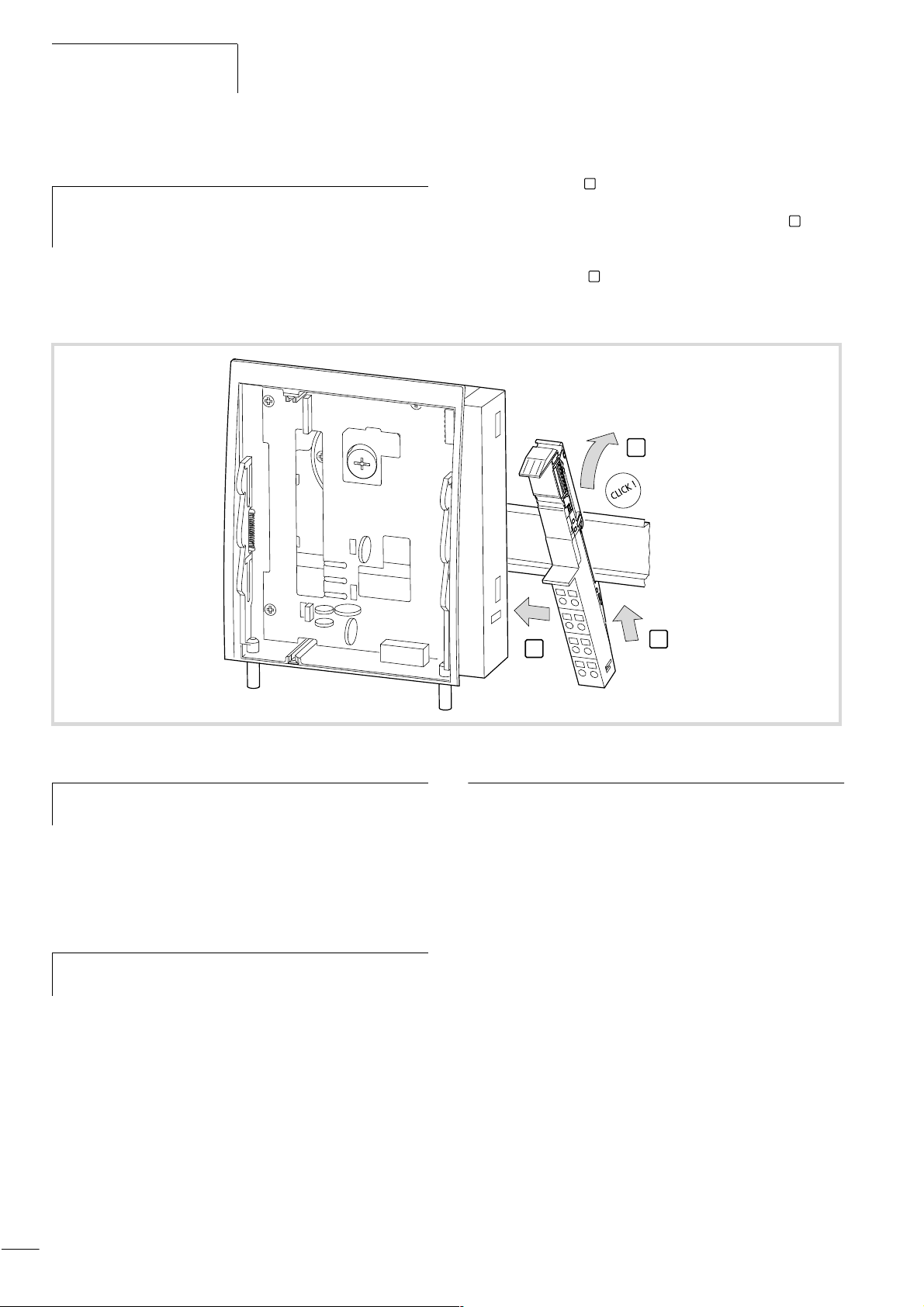
Fitting/removing modules
The back of the base module is provided with an eccentric plate.
Using a cheese head screwdriver, turn this plate so that it grips
underneath the mounting rail and secures the base module. The
front of the plate has number markings to ensure that it is positioned correctly.
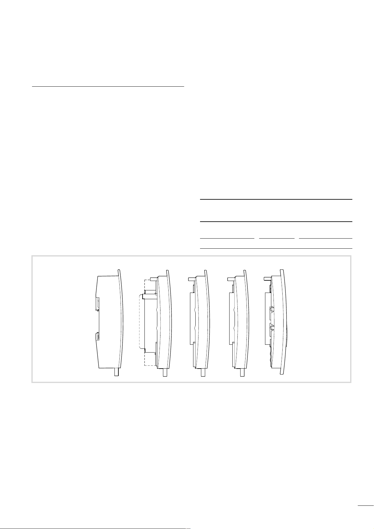
0
1
Figure 2: Fitting the base module
X To fit the controller on the mounting rail, rotate the eccentric
plate until the longer slit is pointing to Position 1 (a Fig. 2).
X Hook the base module on the mounting rail (a Fig. 2).
X Turn the eccentric plate to the right until the base module is
secured firmly.
X Fit the power supply module and then the function modules.
The operator module is the last component to be fitted
(a Fig. 3).
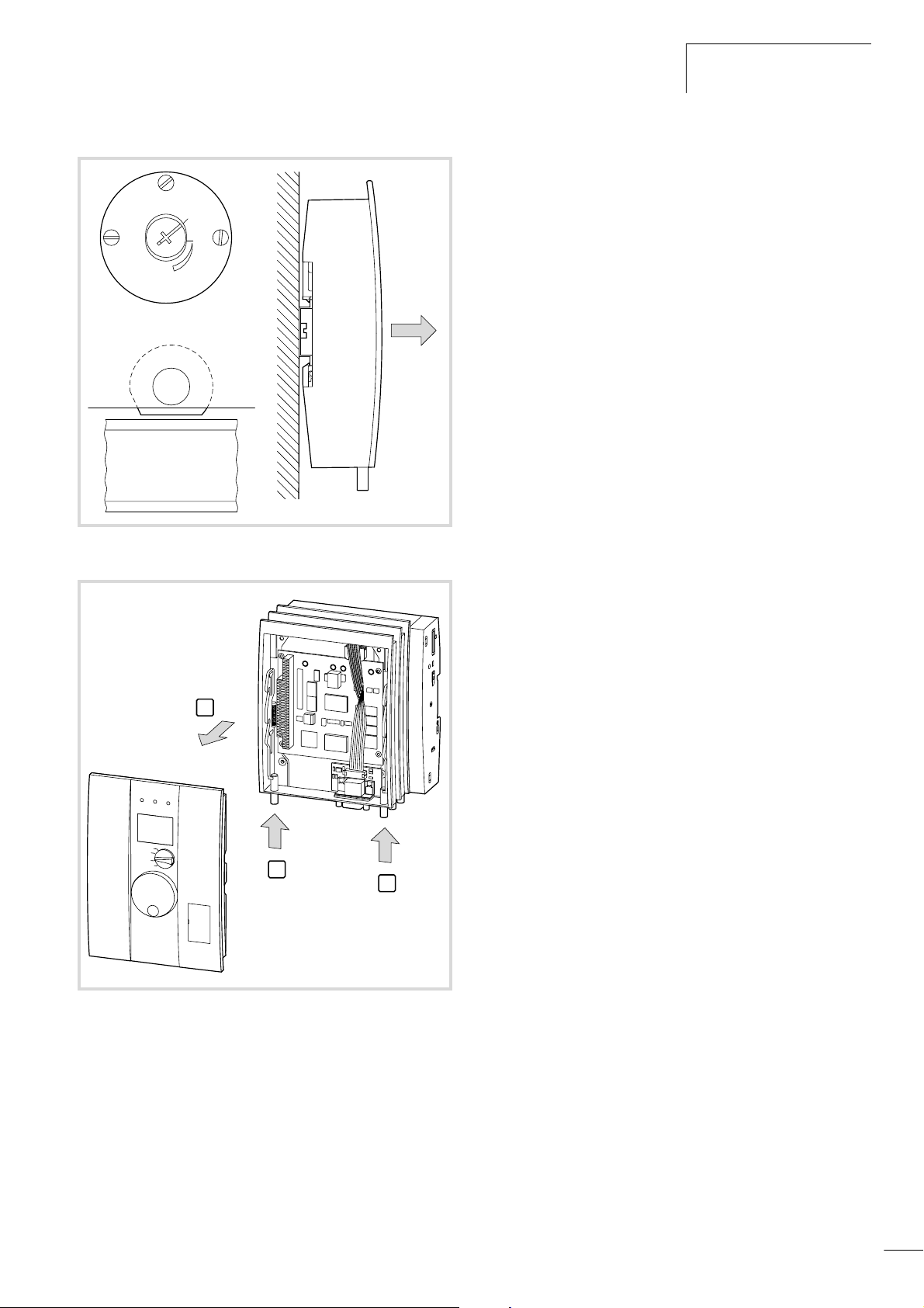
The modules are removed as shown in a Fig. 4 and
h
Fig. 5.
Figure 3: Fitting the modules together
Important!
When fitting the modules together, ensure that the socket
connectors fit exactly into the plug connectors.
6
12/01 AWB2700-1428GB
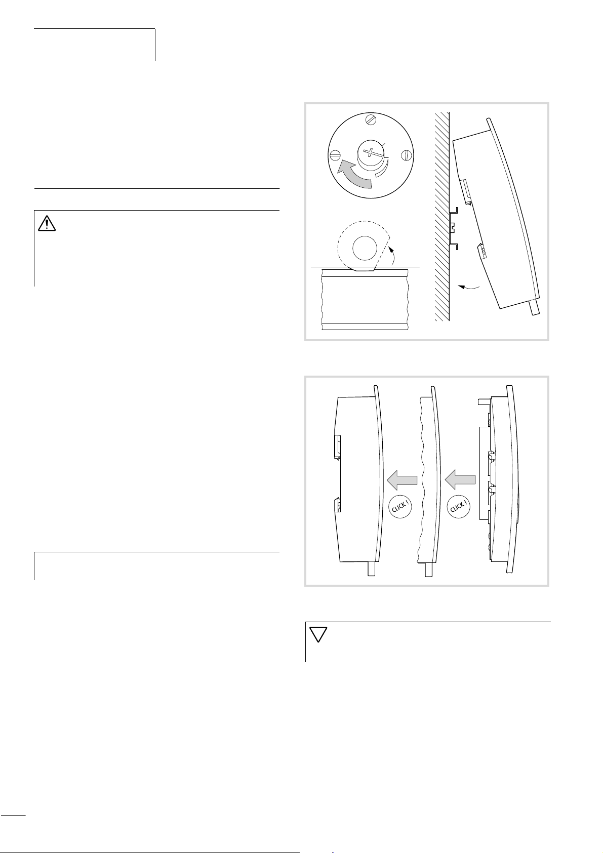
0
1
Mounting
Figure 4: Removing the base module
2
1
1
Figure 5: Detaching the modules
7
Hardware and Engineering
12/01 AWB2700-1428GB
Fitting XI/ON base modules
Further information on mounting and wiring is provided in
h
the XI/ON manuals, e.g. ”Hardware and Engineering” –
XI/ON PROFIBUS-DP (AWB2700-1394).
The XI/ON base modules are fitted on the right of the XC600
controller on the mounting rail:
X Fit the groove of the XI/ON base module onto the mounting rail
from underneath .
X Tilt the upper end back and press the base module against the
mounting rail until you can hear it snap into position
X Push the base module as far left as possible until the two snap
1
2
.
hooks on the side of the adapter or neighbouring base module
click into position .
X Fix the XI/ON modules using the end bracket and end plate on
3
the mounting rail.
2
Figure 6: Fitting XI/ON modules
Wire the base modules after they have been fitted and
h
before you have fitted the electronic modules!
X Once you have fitted all modules, switch on the 24 V power
supply on the XC-POW50-XION-UPS module in order to provide
the 5 V supply to the XI/ON modules.
X Check that the modules are working correctly (no fitting errors,
no gaps).
Only apply the field voltage on the XC600 controller base
h
module after the error-free state of the station is ensured.
3
1
Engineering
Control cabinet design
The arrangement of components in the control cabinet is an important factor in ensuring that system and machine functions are free
of interference. During the planning and design stages, as well as
during implementation, it must be ensured that the power and
control sections are separated. The power section includes the
following components:
• Contactors
• Coupling modules
• Transformers
• Frequency inverters
• Current converters
Dividing the control cabinet into to areas with different power and
interference levels is recommended as an effective prevention
against electromagnetic interference. In small control cabinets,
this can often be provided sufficiently by using separators in order
to reduce interference.
8
12/01 AWB2700-1428GB
Engineering
Ventilation
A minimum gap of 5 cm between passive components must be
provided in order to ensure sufficient ventilation. If active components (e.g. load power supply, transformers) are fitted next to each
other, a minimum gap of 7.5 cm must be ensured. Observe the
values specified in the technical data.
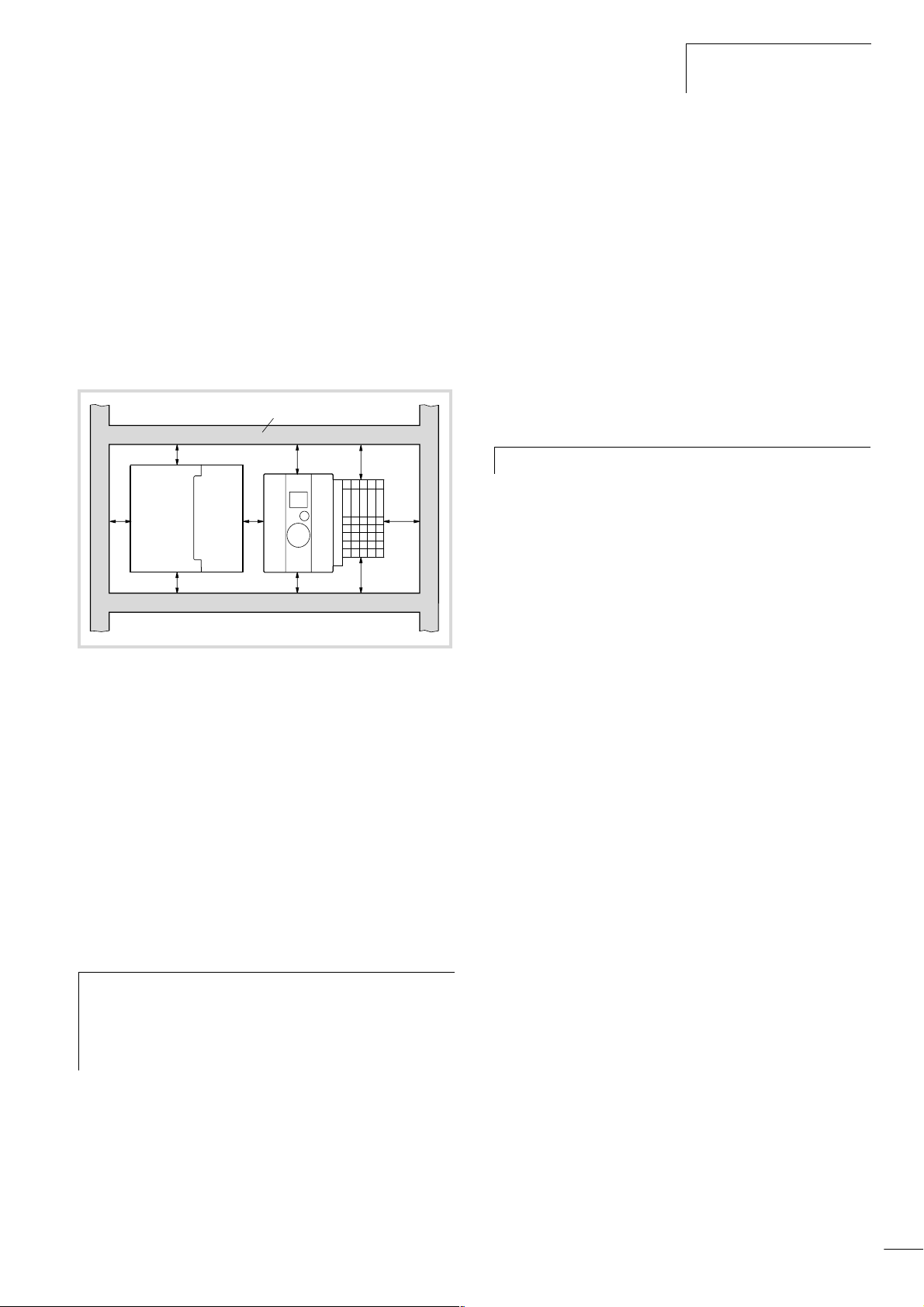
Device arrangement
Mount the UPS unit and the controller horizontally in the control
cabinet as shown in the following figure.
햴
햲
햵
햲
햲 햳
햲
햲
햲
햳
햳
X Observe the following minimum gaps:
– Between heavy current cables and signal cables at least
10 cm
– Between heavy current and data/analog cables at least
30 cm.
– Make sure that the supply and return cables belonging to
each circuit are laid together. The opposing direction of
current flow means that the sum of all the currents is zero, so
that any fields which are produced are compensated.
Suppression of interference sources
X Keep all suppressor circuits as close to the interference source
(contactor, relay, solenoid) as possible.
Switched inductive loads should always be suppressed.
h
Shielding
X Connections to data interfaces should be implemented with
shielded cables. General guideline: the lower the coupling
impedance, the better the shielding effect.
Figure 7: Arrangement in the control cabinet
a Gap > 50 mm
b Gap > 75 mm from active elements
c Cable duct
d UPS unit
Preventing interference
Cabling and wiring
The following cable types are required:
• Heavy current cables (e.g. power cables carrying high currents,
or cables to current converters, contactors, solenoid valves)
• Control and signal cables (e.g. digital input cables)
• Measuring and signal cables (e.g. fieldbus cables)
Keep heavy current cables, control cables and signal
h
cables as far apart from each other as possible. This will
prevent capacitive and inductive interference. If separate
cable routing is not possible, the interference cable must
be shielded.
Ensure correct cable routing inside and outside of the control
cabinet in order to keep interference to a minimum:
X Avoid laying cables with different power levels in parallel.
X Always separate AC from DC cables.
Lightning protection measures
External lightning protection
All cables linking buildings must be shielded. Metal conduits are
recommended as the most suitable means of protection. Signal
cables must be provided with overvoltage protection in the form of
varistors or other overvoltage arresters. This should be implemented as close as possible to the point where the cable is routed
into the building, and at least before the cable enters the control
cabinet.
Internal lightning protection
Internal lightning protection includes all measures that reduce the
effect of lightning current and its electrical and magnetic fields on
the metallic installation and electrical system inside a building
complex. This consists of:
• Lightning protection potential equalisation
• Shielding
• Use of overvoltage protective devices.
Further information on cabling and shielding is provided in the
following manuals:
• AWB27-1287 ”EMC Design Guide for Automation Systems”.
• TB27-001-GB ”The Electromagnetic Compatibility of
Automation Systems”.
• TB27-022-GB ”The Electromagnetic Compatibility (EMC) of
Machines and Plants”.
9
Hardware and Engineering
12/01 AWB2700-1428GB
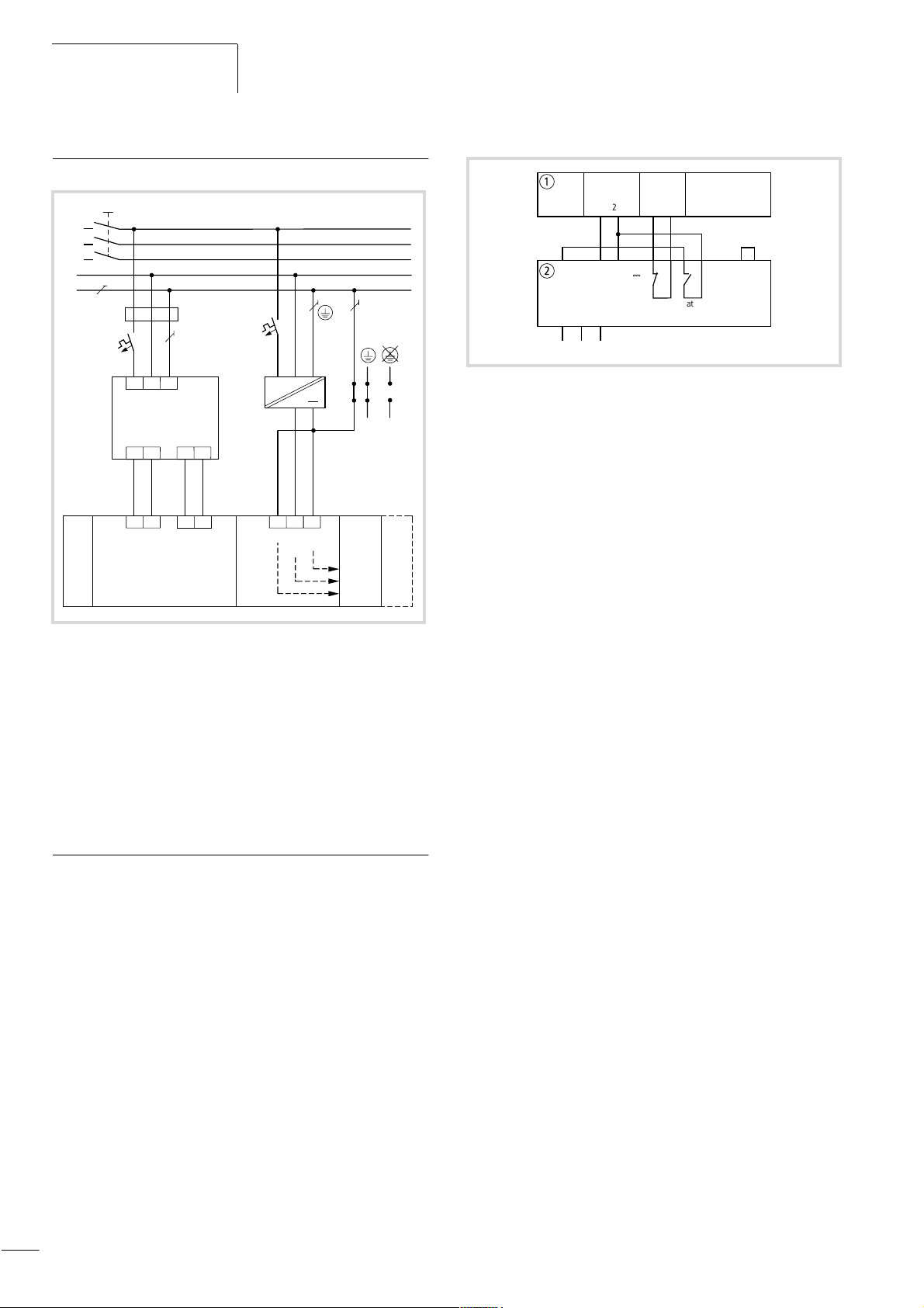
Wiring example (overview)
a
L1
L2
L3
N
PE
b
c
c
d
N
L1
PE
0 V
5
24 V
6
~
+24 V 0 V
f
e
1
1
1
C
24 V
XC-ADP-XION
0 V
XI/ON-Modul
XC600
0
0 V
XC-POW50-
UPS-XION
1
0
24 V
2
Figure 8: Example of wiring
a Main switch
b Delayed switching of the power supply (a Fig. 10)
c Miniature circuit-breaker
d UPS device
e Wiring between UPS device and the XC600 power supply module
(a Fig. 9)
f Non-grounded control circuits must be provided with insulation
monitoring.
Switching the power supply on/off
The UPS ensures that the XC600 controller is switched off properly
in the event of a power supply failure. This requires the inputs/
outputs of the UPS device and the other devices to be wired as
shown below.
a
1
245
b
Batt.
0 V
off
L1 N PE
0 V
Power
Supply
0
3
0 V
24 V
24 V
Power
Fail
0
12
6 7 8 9 10 11 12
H
C1 C2
Power
Supply
Battery
2 min.
UPS
Release
Figure 9: Wiring between UPS device and the XC600 power
supply module
a XC600 (XC-POW50-(XION-)UPS)
b UPS device
If the supply voltage to the UPS device drops, the controller is
supplied with the battery supply voltage. The contact ”C1” in the
UPS device opens and the circuit at the Power Fail input of the
power supply module is interrupted. This will cause the controller
to initiate the PFI signal, which will cause the system to shut down.
The controller requires approximately two minutes to do this.
By connecting the Battery off input of the UPS to contact C2, the
UPS device can switch off the battery supply voltage after two
minutes. The battery is then used only for these two minutes so
that further battery backup protection is ensured occur. If power
is restored after two minutes, the controller will start up again
according to how the operating mode selector switch is set.
A different routine is followed if the power supply to the UPS
returns within two minutes: while the power to the UPS device has
failed, the controller is at first initially supplied by the battery
voltage until power is restored. As the UPS device signals the
power failure to the controller (Power Fail input), the controller
starts a system shutdown (2 minutes). The following message will
be shown on the display: ”PFI shut down in progress”.The operation ends with the message ”TURN OFF YOUR CONTROLLER” on
the display.
In this case, the controller has not detected a power failure. When
the PLC is restarted, the power supply of the UPS system must be
switched off and on again. If the start is to take place automatically, an on-delayed timer must be used to lengthen the interruption to more than 2.5 minutes (a Fig. 10).
10
In the event of a power failure the PLC will then shut down after
two minutes and will restart automatically after 2.5 minutes.
12/01 AWB2700-1428GB
ab
a
L1
K1T
N
PE
Figure 10: Delayed switching of the power supply
a UPS device
K1T
L1
N
PE
XC600
These functions were implemented by adapting the UPS device
supplied by Konzept to the power supply modules of the XC600.
When using a different UPS device, the wiring must be adapted
accordingly.
XC-ADP/XC-ADP-XION base modules
General
A base module and a power supply module form one unit. The
following table shows the combination possibilities of both
modules. The modules only differ in their capability for expansion
with XI/ON modules.
Base module Power supply module Expansion
XC-ADP/XC-ADP-XION base
modules
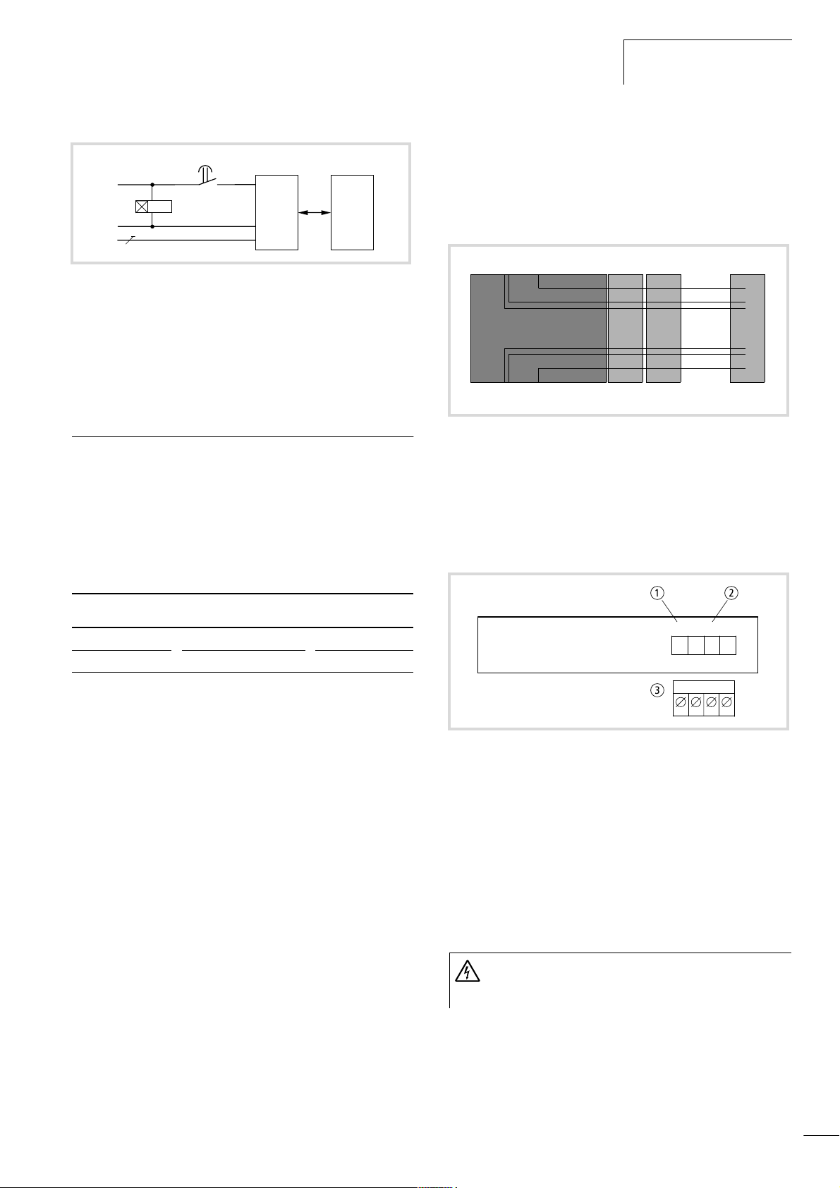
Engineering the XC-ADP-XION base module
Power supply for the XI/ON modules
The 24 V DC power supply required for the load supply of the XI/
ON modules is connected to the base module (a also ”Power
supply module”). The maximum current consumption is 10 A.
XI/ON modulesXC-ADP-XION
cd
Figure 11: Connections between the XC-ADP-XION base module
and the XI/ON modules
a 5 V DC from the power supply module
b Data from the supply module
c Field supply 24 V DC
d C rail connection
Connections
ab
XC-ADP XC-POW50-UPS XI/ON
XC-ADP-XION XC-POW50-XION-UPS –
A base module provides the platform for the other function
modules that are fitted on. The complete unit is then fitted on the
mounting rail.
Task of the XC-ADP-XION module
The module controls the XI/ON data bus and provides the power
supply (5 V) to the XI/ON modules. The base module has a separate connection for the 24 V DC field power supply of the XI/ON
modules. It also has a C connection to which the potential for the
C rails of the XI/ON modules can be connected.
How to expand the controller with XI/ON modules is described in
the XI/ON manuals, ”Hardware and Engineering”, e.g.
AWB2700-1394.
Task of the XC-ADP module
This is used as a platform for other modules.
24V 0V11C
1
Field
Supply
c
Figure 12: 24 V DC and C1 connections of the XC-ADP-XION
a 24 V DC connection
b C rail connection
c Plug-in terminals, connection cross-sections:
– flexible with ferrule 0.5 mm
– solid 0.5 mm2 to 2.5 mm
2
to 2.5 mm
2
2
The C1 connection is routed to the XI/ON modules. It is used for
providing an additional common potential, e.g. PE.
XI/ON modules that have a C in their designation, e.g. S4T S-B-CS, require the provision of a common C rail.
Warning!
The maximum load on the C rail and C1 connection is
24 V!
11
Hardware and Engineering
12/01 AWB2700-1428GB
Expansion with XI/ON modules
The following XI/ON base modules can be connected directly to
the XC-ADP-XION base module:
• Modules with tension clamp connection
• Modules with screw connections without C rail
Bus refreshing modules and power feeding modules cannot be
connected directly.
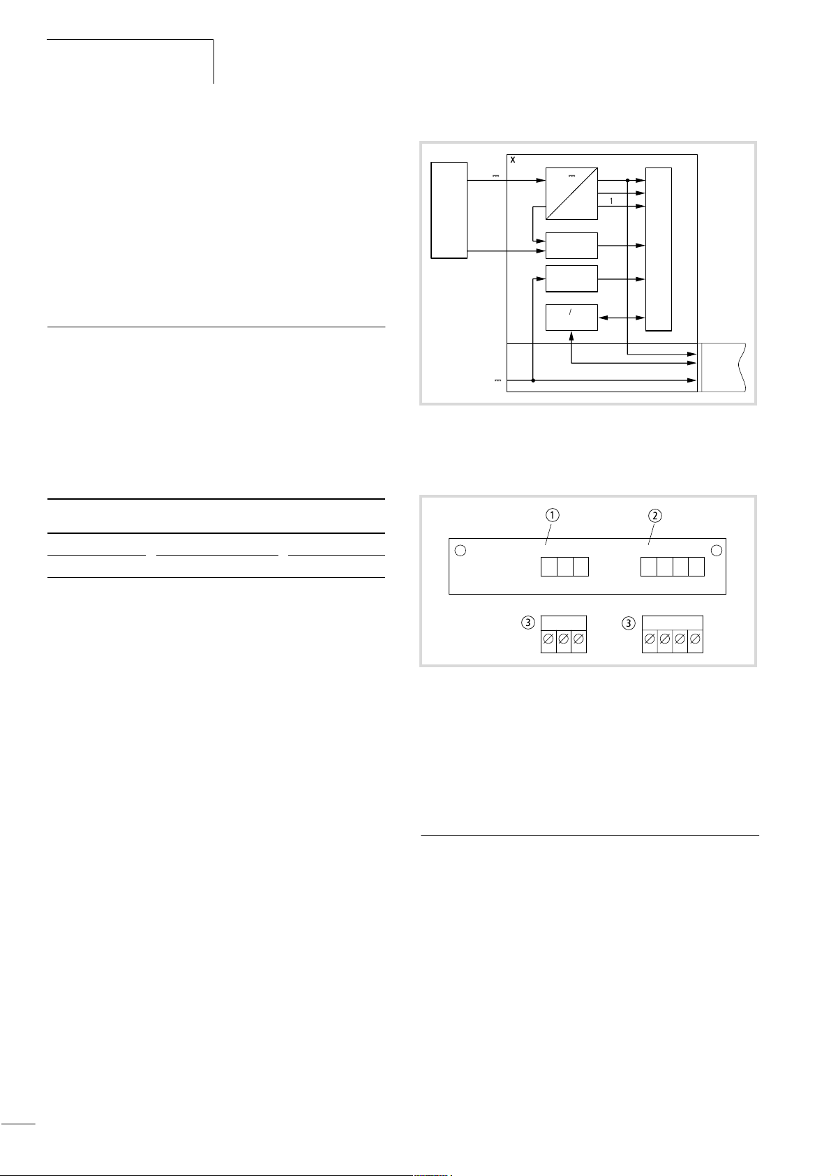
XC-POW50-UPS/XC-POW50-XION-UPS power supply modules
General
A base module and a power supply module form one unit. The
following table shows the combination possibilities of both
modules. The only difference between the modules is their expansion capability with XI/ON modules.
Base module Power supply module Expansion
XC-ADP XC-POW50-UPS XI/ON
XC-ADP-XION XC-POW50-XION-UPS –
24 V
Power
Fail
24 V
H
H
XC-POW50-XION-UPS
24 V
H
Power
Fail
Diagnostics
XI/0N
ISA Interface
XC- ADP-XION
5 V
+12 V
–12 V
ISA-BUS
USV
Figure 13: Block diagram of the power supply module
Engineering
a
12 24Vo 0Vo
Power Fail
Power
b
Supply
XI/ON
Modulebus
Fieldbussupply
Task
The modules convert the 24 V DC power supply to +5 V DC,
+12 V DC and –12 V DC (for XC-POW50-XION-UPS) supplies, and
provide the voltages for the function modules via the PC/104+
bus. The XC-POW50-XION-UPS power supply module also
provides a 5 V DC supply to XI/ON modules via the XI/ON module
bus.
As the XC600 controller is PC-based, it must be ensured that the
program is closed and the operating system shut down properly
before the device is switched off. The supply of the power supply
module must therefore be backed up by means of an uninterruptible power supply (UPS). If the supply voltage drops, the UPS sends
a Power Fail signal to the PLC which then initiates a shutdown of
the system. The UPS unit will then keep the output voltage
constant for at least two minutes in order to ensure the troublefree completion of the shutdown.
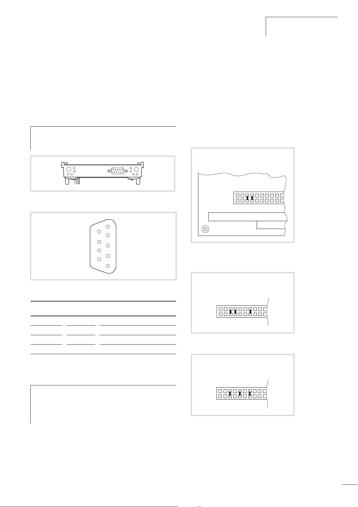
Setup
The module contains a board with the PC/104+ bus. Another
board provides the interface for the XI/ON modules and connects
the power supply module with the base module.
c
c
Figure 14: Connections of the XC-POW50-UPS/
XC-POW50-XION-UPS
a Power Fail connection
b 24 V DC connection
c Plug-in terminals, connection cross-sections:
– flexible with ferrule 0.5 mm
– solid 0.5 mm2 to 2.5 mm
2
2
to 2.5 mm
2
XC-NET-DP-M PROFIBUS-DP module
General
The module provides the interface between the CPU module and
the PROFIBUS-DP bus that is compliant with industrial standard
EN 50170 Vol. 2.
Task
12
The module provides the master function for PROFIBUS-DP. It
organises and operates the data exchange between the user
program and the connected slaves. Up to 31 slaves can be
connected to one line. Several sections can be connected together
using repeaters, enabling up to 125 slaves to be connected.
12/01 AWB2700-1428GB
XC-NET-DP-M PROFIBUS-DP
module
The PROFIBUS-DP module can be fitted between the power supply
module and the CPU module.
Engineering
PROFIBUS-DP interface
Connect the module to the PROFIBUS-DP bus via the isolated
RS 485 interface (9-pole SUB-D socket/plug connector).
Use the special ZB4-209-DS2 PROFIBUS-DP plug. It
h
provides the wiring required for trouble-free operation up
to 12 Mbit/s.
Figure 15: Connections of the PROFIBUS-DP module
5
9
4
8
3
7
2
6
1
Devices that are still connected with the PLC will continue to be
interrogated.
Configuring the module address
Up to three XC-NET-DP-M (PROFIBUS-DP) or XC-NET-CAN
(CANopen) modules can be used in any combination. Reserve a
memory range for each module in the CPU by defining a module
address for each one:
Setting the address on the device
X Set the address for each module using jumpers on the jumper
field in the jumper area 13 to 19 (a following figures).
1. r CE000*
110
0111
19 18 17 16 15 14 13
Figure 17: Address setting of module 1
* Factory setting
Figure 16: Pin assignment of the PROFIBUS-DP interface
SUB-D plug Signal Meaning
3 RxD/TxD-P Receive/send data P
5 DGND Data reference potential
6 VP Supply voltage plus pole
8 RxD/TxD-N Receive/send data N
Power supply
The power supply module provides the 5 V supply to the modules
via the PC/104+ bus.
Set up the system power supply so that the connected
h
remote stations on the PROFIBUS-DP line are switched on
simultaneously or before the controller. This prevents any
errors occurring during the starting of the PROFIBUS-DP
line.
Start/Stop behaviour
Setting the OMS to the STOP position will cause all the outputs of
the remote devices to be set to 0.
An interruption on the DP line will cause all inputs of the disconnected devices (receive data) to be interpreted by the PLC as 0
signals and the outputs set by the PLC in the output module to be
reset.
2. r CC000
110
0110
19 18 17 16 15 14 13
Figure 18: Address setting of module 2
3. r D4000
110
1010
19 18 17 16 15 14 13
Figure 19: Address setting of module 3
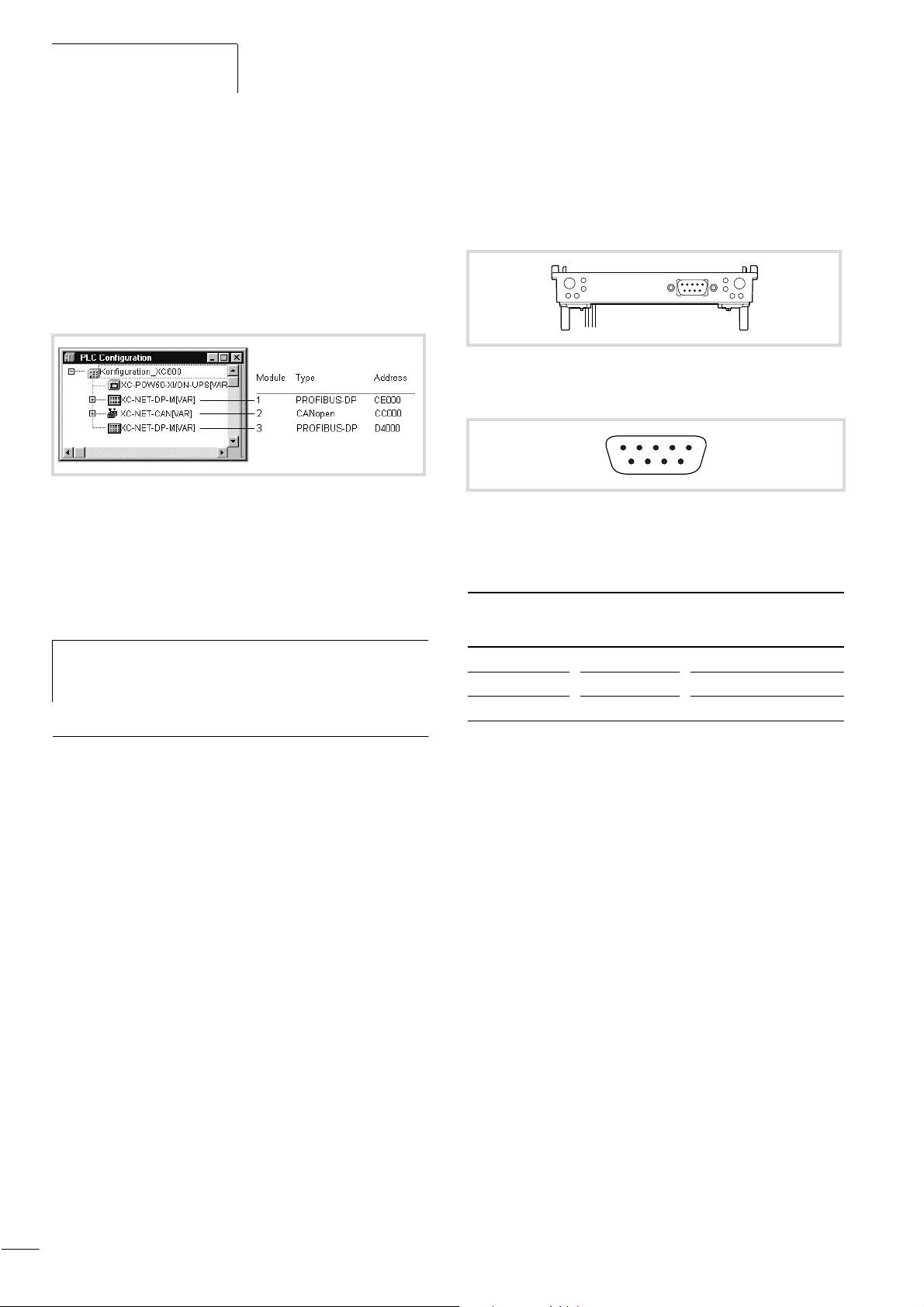
Setting the address in XSoft
Assign the input/output address range (%IB/%QB) to the modules
in the PLC configuration in XSoft. The modules are integrated in
turn into the PLC configuration:
13
Hardware and Engineering
12/01 AWB2700-1428GB
X Assign the memory range beginning with start address CE000
to the first module (CANopen or PROFIBUS-DP) to be
configured.
The input/output devices assigned to this module are connected to
the module bus system via address CE000.
X Assign the range starting with address CC000 to the second
module and D4000 to the third.
Figure 20: Example configuration with three modules and the
assigned addresses
Bus terminating resistors
Bus terminating resistors must be provided at both ends of the
cable.
Engineering
CANopen interface
The module can be connected to the CANopen bus via the isolated
ISO 11898 interface.
Figure 21: CANopen interface
Pin assignment
34125
8967
Figure 22: Pin assignment of the CANopen interface
Connector assignment in accordance with the CiA DS 102
(CAN Physical Layer for Industrial Applications) standard.
SUB-D plug
connector
Signal Meaning
When using the ZB4-209-DS2 PROFIBUS plug, the bus
h
terminating resistor can be enabled or disabled via the
slide switch on the plug.
XC-NET-CAN CANopen module
General
The module provides the ISO 11898 interface between the CPU
module and the CANopen bus.
Task of the module
The module provides the master function for CANopen bus. It
organises and operates the data exchange between the user
program and the connected slaves. Up to 126 nodes can be
connected to a line.
The CANopen modules can be fitted between the power supply
module and the CPU module. Up to three modules (PROFIBUS-DP
or CANopen) can be fitted.
2 CAN_L CAN_L bus cable
3 CAN_GND CAN reference potential
7 CAN_H CAN_H bus cable
Power supply
The power supply module provides the 5 V supply to the modules
via the PC/104 bus.
Set the system power supply so that the connected remote stations
on the CANopen line are switched on simultaneously or before the
controller. This prevents any errors occurring during the starting of
the CANopen line.
Start/Stop behaviour
Setting the OMS to the STOP position will cause all the outputs of
the remote devices to be set to 0.
An interruption on the line will cause all inputs of the disconnected
devices (receive data) to be interpreted by the PLC as 0 signals and
the outputs set by the PLC in the output module to be reset.
Devices that are still connected with the PLC will continue to be
interrogated.
Configuring the module address
Up to three XC-NET-DP-M (PROFIBUS-DP) or XC-NET-CAN
(CANopen) modules can be used in any combination. Reserve a
memory range for each module in the CPU by defining a module
address for each one:
14
X Set the address for each module using the jumpers in the
jumper field from range 13 to 17 (a following figures).

12/01 AWB2700-1428GB
1. r CE000*
14
13
111
Figure 23: Address setting of module 1
* Factory setting
171615
00
XC-NET-CAN CANopen module
Figure 26: Example configuration with three modules and the
assigned addresses
Bus terminating resistors
120 O bus terminating resistors must be provided at the ends of
the networks. Standard plugs are available that allow the bus
terminal resistor to be enabled or disabled via a slide switch on the
plug, e.g. the SUBCON-PLUS-CAN plug from Phoenix Contact,
Order No. 2744694
2. r CC000
14
13
011
171615
00
Figure 24: Address setting of module 2
3. r D4000
14
13
010
171615
10
Figure 25: Address setting of module 3
Assign the input/output address range (%IB/%QB) to the module
in the PLC configuration in XSoft:
The modules are integrated in turn into the PLC configuration:
Only use CANopen-approved cable with the following features:
• Ripple resistance 108 to 132 O
• Capacitance < 50 pf/m
CAN_H
CAN_L
CAN_GND
120 O
Figure 27: CANopen cable
Baud rate
[kbits/s]
F Length
[m]
Cable cross-section
2
[mm
]
20 1000 0.75 to 0.80 16 O/km
125 500 0.50 to 0.60 40 O/km
250 250 0.50 to 0.60 40 O/km
500 100 0.34 to 0.60 60 O/km
1000 40 0.25 to 0.34 70 O/km
120 O
Loop
resistance
CAN_H
CAN_L
CAN_GND
Assign the memory range beginning with start address CE000 to
the first module (CANopen or PROFIBUS-DP) to be configured. The
input/output devices assigned to this module are connected to the
module bus system via address CE000. Assign the range starting
with address CC000 to the second module and D4000 to the third.
15
 Loading...