

Page 1

Motorschutzrelais
ZB12 und ZB32
Überlastüberwachung
von EEx e-Motoren
Motor-protective
relays ZB12 and ZB32
Overload monitoring of
EEx e motors
Hardware und Projektierung
Hardware and Engineering
05/05 AWB2300-1527D/GB
Page 2

Alle Marken- und Produktnamen sind Warenzeichen oder
eingetragene Warenzeichen der jeweiligen Titelhalter.
1. Auflage 2004, Redaktionsdatum 02/04
2. Auflage 2005, Redaktionsdatum 05/05
siehe Änderungsprotokoll im Kapitel „Zu diesem Handbuch“
© Moeller GmbH, Bonn
Autor: Wolfgang Nitschky
Redaktion: Heidrun Riege
Alle Rechte, auch die der Übersetzung, vorbehalten.
Kein Teil dieses Handbuches darf in irgendeiner Form
(Druck, Fotokopie, Mikrofilm oder einem anderen Verfahren)
ohne schriftliche Zustimmung der Firma Moeller GmbH,
Bonn, reproduziert oder unter Verwendung elektronischer
Systeme verarbeitet, vervielfältigt oder verbreitet werden.
Änderungen vorbehalten.
Gedruckt auf Papier aus chlor- und säurefrei
gebleichtem Zellstoff.
All brand and product names are trademarks or registered
trademarks of the owner concerned.
st
1
published 2004, edition date 02/04
nd
2
edition 05/2005
See revision protocol in the “About this manual“ chapter
© Moeller GmbH, Bonn
Author: Wolfgang Nitschky
Editor: Heidrun Riege
Translator: David Long
All rights reserved, including those of the translation.
No part of this manual may be reproduced in any form
(printed, photocopy, microfilm or any otherprocess) or
processed, duplicated or distributed by means of electronic
systems without written permission of Moeller GmbH, Bonn.
Subject to alterations without notice.
Printed on bleached cellulose.
100 % free from chlorine and acid.
Page 3

Warnung!
Gefährliche
elektrische
Spannung!
Warning!
Dangerous
electrical voltage!
Vor Beginn der Installationsarbeiten
• Gerät spannungsfrei schalten.
• Gegen Wiedereinschalten sichern.
• Spannungsfreiheit feststellen.
• Erden und kurzschließen.
• Benachbarte, unter Spannung stehende
Teile abdecken oder abschranken.
• Die für das Gerät angegebenen Montagehinweise (AWA) sind zu beachten.
• Nur entsprechend qualifiziertes Personal
gemäß EN 50110-1/-2 (VDE 0105
Teil 100) darf Eingriffe an diesem
Gerät/System vornehmen.
• Achten Sie bei Installationsarbeiten darauf,
dass Sie sich statisch entladen, bevor Sie
das Gerät berühren.
• Schwankungen bzw. Abweichungen der
Netzspannung vom Nennwert dürfen die in
den technischen Daten angegebenen Toleranzgrenzen nicht überschreiten, andernfalls sind Funktionsausfälle und Gefahrenzustände nicht auszuschließen.
• Einbaugeräte für Gehäuse oder Schränke
dürfen nur im eingebauten Zustand
betrieben und bedient werden.
Before commencing the installation
• Disconnect the power supply of the device.
• Ensure relosing interlock that devices
cannot be accidentally restarted.
• Verify isolation from the supply.
• Connect to earth and short-circuit.
• Cover or fence off neighbouring live parts.
• Follow the installation instructions (AWA)
included with the device.
• Only suitably qualified personnel
in accordance with EN 50110-1/-2
(VDE 0105 Part 100) may work on this
device/system.
• Before installation and before touching
the device ensure that you are free
of electrostatic charge.
• The rated value of the mains voltage may
not fluctuate or deviate by more than the
tolerance specified, otherwise malfunction
and hazardous states are to be expected.
• Panel-mount devices may only be operated
when properly installed in the cubicle or
control cabinet.
Moeller GmbH
Sicherheitshinweise/Safety instructions
I
Page 4

05/05 AWB2300-1527D/GB
Überblick/Overview
Motorschutzrelais ZB12 und ZB32
Überlastüberwachung von EEx e-Motoren 1
ZB12 and ZB32 motor-protective relays
Overload monitoring of EEx e motors 27
Anhang/Appendix 53
II
Page 5

05/05 AWB2300-1527D/GB
Inhalt
Zu diesem Handbuch 3
Zielgruppe 3
Abkürzungen und Symbole 3
Änderungsprotokoll 4
1 Motorschutzrelais ZB12 und ZB32 5
Vorwort 5
Geräteübersicht 5
Gerätebeschreibung 6
– Überlastschutz mit Bimetallrelais 6
– Strombereiche der Motorschutzrelais 7
– Temperaturkompensation 9
– Phasenausfall 9
– Wiedereinschaltung 10
– Testfunktion 11
2 Projektierung 13
Überlastüberwachung von Motoren im
EEx e-Bereich 13
Einstellung der Überstromschutzeinrichtung 13
– Kurzschlussschutz der Motorschutzrelais 14
Zulassungen 17
3 Installation 19
Hinweise zur Installation 19
Geräte montieren 21
4 Geräte betreiben 25
Einstellungen 25
– Rücksetzung 25
–Test 26
1
Page 6

Inhalt
05/05 AWB2300-1527D/GB
Anhang/Appendix 53
Typenschilder/Rating plates 53
– Motorschutzrelais/Overload relay ZB12
und/and ZB32 53
Auslösekennlinien/
Tripping characteristics 55
– ZB12-0,16 und/and ZB32-0,16 56
– ZB12-0,24 und/and ZB32-0,24 58
– ZB12-0,4 und/and ZB32-0,4 60
– ZB12-0,6 und/and ZB32-0,6 62
– ZB12-1 und/and ZB32-1 64
– ZB12-1,6 und/and ZB32-1,6 66
– ZB12-2,4 und/and ZB32-2,4 68
– ZB12-4 und/and ZB32-4 70
– ZB12-6 und/and ZB32-6 72
– ZB12-10 und/and ZB32-10 74
– ZB12-12 76
– ZB12-16 78
– ZB32-16 80
– ZB32-24 82
– ZB32-32 84
Konformitätserklärung/Declaration of
Conformity 86
2
Page 7
05/05 AWB2300-1527D/GB
Zu diesem Handbuch
Das vorliegende Handbuch gilt für die Motorschutzrelais
ZB12 und ZB32.
Dieses Handbuch beschreibt die Überlastüberwachung zum
Schutz von EEx e-Motoren in explosiongefährdeten Bereichen.
Zielgruppe Dieses Handbuch richtet sich an Fachpersonal, das die
Motorschutzrelais installiert, in Betrieb nimmt und wartet.
Abkürzungen und Symbole In diesem Handbuch werden Abkürzungen und Symbole
eingesetzt, die folgende Bedeutung haben:
EEx e Zündschutzart „Erhöhte Sicherheit“
PTB Physikalisch Technische Bundesanstalt, Zerti-
fizierungsstelle für Geräte im EEx-Bereich
NM Niedrigster möglicher Einstellstrom
HM Höchster möglicher Einstellstrom
h
h
i
X zeigt Handlungsanweisungen an
macht Sie aufmerksam auf interessante Tipps und
Zusatzinformationen
Achtung!
warnt vor leichten Sachschäden.
Vorsicht!
warnt vor schweren Sachschäden und leichten
Verletzungen.
3
Page 8
Zu diesem Handbuch
j
Änderungsprotokoll
05/05 AWB2300-1527D/GB
Warnung!
warnt vor schweren Sachschäden und schweren
Verletzungen oder Tod.
Für eine gute Übersichtlichkeit finden Sie auf den linken
Seiten im Kopf die Kapitelüberschrift und auf den rechten
Seiten den aktuellen Abschnitt, Ausnahmen sind Kapitelanfangsseiten und leere Seiten am Kapitelende.
Redaktionsdatum
05/05 6 Abschnitt „Direktanbau“ j
Seite Stichwort neu Ände-
rung
8 Tabelle 1 „Strombereiche ZB12 Relais“ j
9 Abschnitt „Temperaturkompensation“ j
15 Tabelle 3 „ZB12 in Direktanbau“ j
16 Tabelle 4 „ZB32 in Direktanbau oder
Einzelaufstellung“
21 Tabelle 5 „Direktanbau“ j
54 Tabelle 9 „Werte der einzelnen Typen“ j
78 Auslösekennlinie „ZB12-16“ j
j
entfällt
4
Page 9

05/05 AWB2300-1527D/GB
1 Motorschutzrelais ZB12 und ZB32
Vorwort Für den Schutz von Motoren in explosionsgefährdeten
Bereichen gelten zusätzlich zu den Vorschriften nach
EN 60079-14 und VDE 0165 Teil 1 separate Vorschriften für
die entsprechenden Zündschutzarten. Für Motoren in der
Zündschutzart „e“ „Erhöhte Sicherheit“ verlangt die
Vorschrift EN 50019 zusätzliche Maßnahmen. Durch diese
werden mit einem erhöhten Grad an Sicherheit die Möglichkeiten von unzulässig hohen Temperaturen und das
Entstehen von Funken und Lichtbögen an Motoren, bei
denen dies im normalen Betrieb nicht auftritt, verhindert. Die
Motorschutzgeräte hierfür, die sich selber nicht im
EEx e-Bereich befinden, müssen durch eine akkreditierte
Zulassungsstelle zertifiziert sein.
Die Richtlinie 94/9/EG (ATEX 100a) zur Angleichung der
Rechtsvorschriften der Mitgliedsstaaten für Geräte und
Schutzsysteme zur bestimmungsmäßigen Verwendung in
explosionsgefährdeten Bereichen ist ab dem 30.06.2003
bindend.
Geräteübersicht
Die Motorschutzrelais ZB12 und ZB32 sind nach der Richtlinie 94/9/EG (ATEX 100a) durch die PTB zugelassen.
a Die EG-Baumusterprüfbescheinigungs-Nummern lauten:
ZB12: PTB 04 ATEX 3022
ZB32: PTB 04 ATEX 3022
Abbildung 1: Motorschutzrelais ZB12
5
Page 10
Motorschutzrelais ZB12 und
ZB32
Abbildung 2: Motorschutzrelais ZB32
05/05 AWB2300-1527D/GB
Gerätebeschreibung Überlastschutz mit Bimetallrelais
Die Motorschutzrelais ZB12 und ZB32 sind dreipolige elektromechanische Motorschutzrelais mit Bimetallen. Sie sind
zur Überwachung von Gleich- und Wechselstrom geeignet.
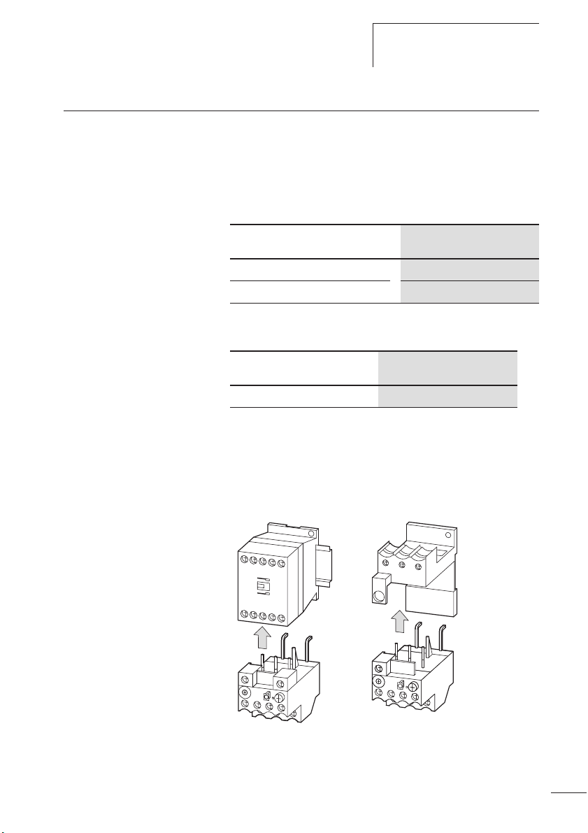
Die Motorschutzrelais ZB12 und ZB32 sind als Direktanbau
an die Schütze DIL einsetzbar.
Direktanbau
Motorschutzrelais Schütz
ZB12 DILM7
DILM9
DILM12
DILM15
ZB32
DILM17
DILM25
DILM32
Zusätzlich ist das Relais ZB32 in Kombination mit einer
Einzelaufstellung einzeln einsetzbar.
Einzelaufstellung
Motorschutzrelais
ZB32 ZB32-XEZ
Einzelaufstellung
Bei einer Überlastauslösung schalten die Hilfsschalter 95-96
und 97-98 um und unterbrechen den Steuerstromkreis des
zugehörigen Leistungsschützes. Sie schalten so indirekt den
Stromfluss des zu überwachenden Motors ab.
6
Page 11
05/05 AWB2300-1527D/GB
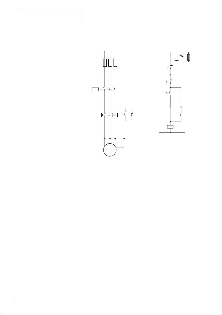
Gerätebeschreibung
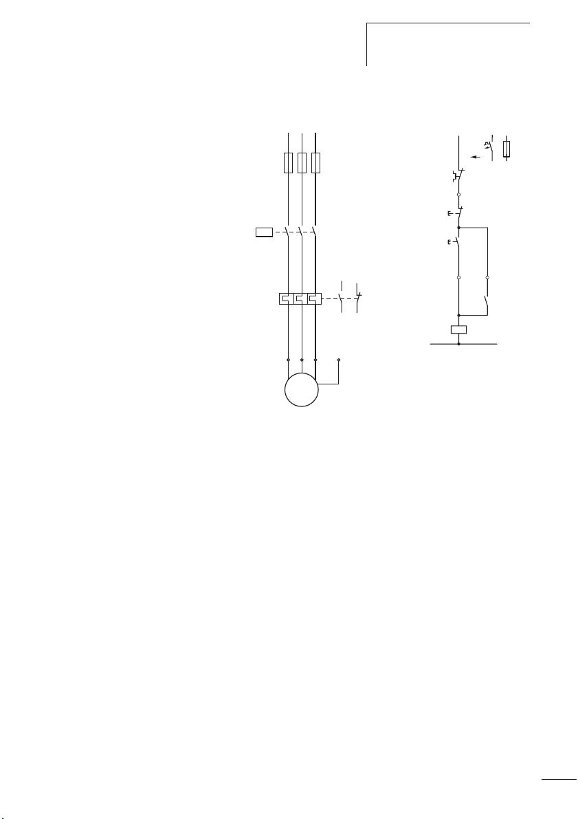
L1 L2 L3
Q11
F1
F2
135
246
246
UVW
979795
96
PE
-F2
0
-S11
I
-Q11
N
M
3~
M1
Abbildung 3: Schaltbild eines Motorabganges mit
Motorschutzrelais
F1 Sicherung
F2 Motorschutzrelais
K1M Motorschütz
M1 Motor
L1
(Q11/1)
95
96
21
22
13
14
-Q11
A1
A2
-F0
14
13
Strombereiche der Motorschutzrelais
Die Z-Relais werden mit Hilfe einer Strom-Einstellscheibe auf
den Motornennstrom eingestellt.
Mit verschiedenen Typen können Motoren von 0,1 bis 32 A
Motornennstrom überwacht werden.
7
Page 12
Motorschutzrelais ZB12 und
ZB32
05/05 AWB2300-1527D/GB
Tabelle 1: Strombereiche ZB12 Relais
Typ
ZB12-0,16 0,1 bis 0,16
ZB12-0,24 0,16 bis 0,24
ZB12-0,4 0,24 bis 0,4
ZB12-0,6 0,4 bis 0,6
ZB12-1,0 0,6 bis 1,0
ZB12-1,6 1,0 bis 1,6
ZB12-2,4
ZB12-4 2,4 bis 4,0
ZB12-6 4,0 bis 6,0
ZB12-10 6,0 bis 10
ZB12-12 9 bis 12
ZB12-16 12 bis 16
Tabelle 2: Strombereiche ZB32 Relais
Typ
ZB32-0,16 0,1 bis 0,16
ZB32-0,24 0,16 bis 0,24
ZB32-0,4 0,24 bis 0,4
ZB32-0,6 0,4 bis 0,6
ZB32-1,0 0,6 bis 1,0
ZB32-1,6 1,0 bis 1,6
ZB32-2,4 1,6 bis 2,4
ZB32-4
ZB32-6 4,0 bis 6,0
ZB32-10 6,0 bis 10
ZB32-16 10 bis 16
ZB32-24 16 bis 24
ZB32-32 24 bis 32
8
Strombereich I [A]
1,6 bis 2,4
Strombereich I [A]
2,4 bis 4,0
Page 13
05/05 AWB2300-1527D/GB
Gerätebeschreibung
Temperaturkompensation
Zwei Parameter beeinflussen die Ausbiegung der Bimetalle.
Zum einen ist das die Wärme, die proportional zum fließendem Strom erzeugt wird und zum anderen ist das der
Einfluss der Umgebungstemperatur.
Der Einfluss der Umgebungstemperatur wird mit Hilfe eines
zusätzlichen Bimetalls, das nicht vom Motorstrom durchflossen wird, im Temperaturbereich –5 °C bis +55 °C kontinuierlich durch Korrektur des Auslöseweges selbsttätig
kompensiert.
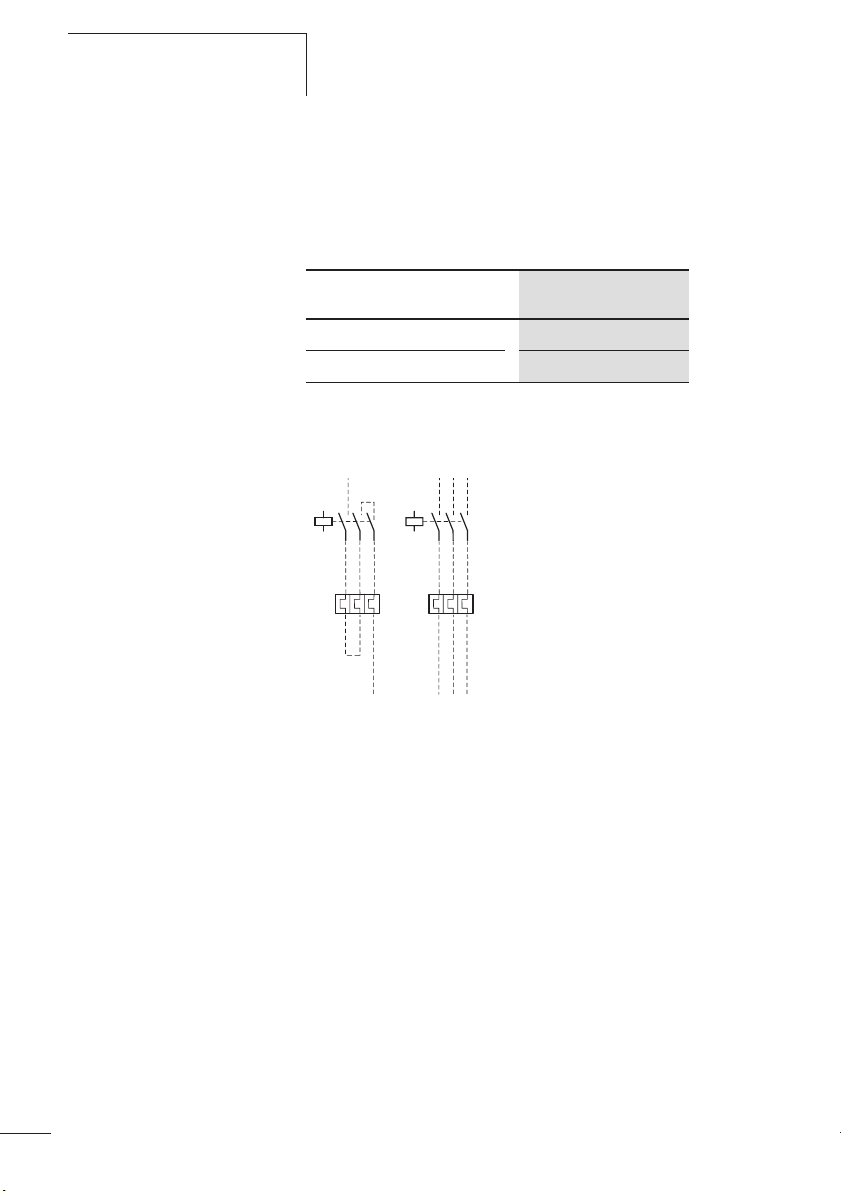
Phasenausfall
Motorschutzrelais ZB12 und ZB32 sind phasenausfallempfindlich. Die Auslenkung aller drei Bimetalle wirkt auf eine
Auslösebrücke, die bei Erreichen des Grenzwertes einen
Sprungschalter umschaltet. Gleichzeitig verschieben alle drei
Bimetalle die Differenzialbrücke. Wird bei einem Phasenausfall ein Bimetall weniger ausgelenkt, bleibt die Differentialbrücke zurück und der Weg wird in zusätzlichen Auslöseweg
umgewandelt, so dass es zu einer vorzeitigen Auslösung
kommt.
햴
햲
햳
97S95
98 96
97 95
98 96
Normalbetrieb ungestört dreiphasige Überlast Ausfall einer Phase
(zweiphasige Belastung)
Abbildung 4: Funktion der Phasenausfallempfindlichkeit mit Hilfe
einer Auslöse- und Differenzialbrücke
a Auslösebrücke
b Differenzialbrücke
c Differenzweg
s = Auslöseweg
97 95
98 96
9
Page 14
Motorschutzrelais ZB12 und
ZB32
05/05 AWB2300-1527D/GB
h
Soll mit einem ZB12 oder ZB32 Relais ein Wechselstrommotor oder ein Gleichstrommotor überwacht werden,
muss der Strom über alle drei Strombahnen geführt
werden, um Frühauslösungen zu vermeiden.
Abbildung 5: Verdrahtung der Motorschutzrelais für den Schutz
von Wechselstrom- oder Gleichstrommotoren
(Reihenschaltung der Bimetallauslöser)
(a Abschnitt „Auslösekennlinien“ ab Seite 55)
Wiedereinschaltung
Nach einer Auslösung müssen zunächst die Bimetalle
abkühlen, bevor das Motorschutzrelais wieder zurückgesetzt
werden kann. Mittels eines Wahlschalters kann zwischen
manuellem und automatischer Rücksetzung gewählt werden
(a Abschnitt „Rücksetzung“auf Seite 25).
10
j
In der Stellung Automatik fallen die Kontakte nach der
Abkühlung der Bimetalle automatisch zurück, in der Handstellung muss die Auslösung vor Ort am Motorschutzrelais
quittiert werden.
Warnung!
Für den Explosionsschutz ist nur ein manuelles Rücksetzen/Einschalten der Bimetalle des Motorschutzrelais
oder ein automatisches Zuschalten über eine Steuerungsverriegelung zum Motor bzw. zur elektrischen Maschine
zulässig
Rücksetzungen dürfen manuell vor Ort oder durch
geschultes Personal in der Leitwarte vorgenommen
werden.
Page 15

05/05 AWB2300-1527D/GB
Gerätebeschreibung
Testfunktion
Durch eine zusätzliche Testtaste kann die Funktionstüchtigkeit der Hilfsschalter kontrolliert werden. Hierbei hat die
Testtaste eine Doppelfunktion:
• Das Drücken der Testtaste öffnet den Öffner 95-96. Nach
dem Loslassen fällt der Öffner wieder zurück.
Diese Funktion kann zum manuellen Ausschalten des
Motors genutzt werden.
• Das Ziehen der Testtaste führt zur Auslösung des Motorschutzrelais. Der Öffner 95-96 öffnet und der Schließer
97-98 schließt. Nach dem Loslassen der Testtaste muss
das Motorschutzrelais wie nach einer Auslösung zurückgesetzt werden (a Abschnitt „Wiedereinschaltung“auf
Seite 10).
11
Page 16

05/05 AWB2300-1527D/GB
12
Page 17

05/05 AWB2300-1527D/GB
2 Projektierung
Überlastüberwachung von Motoren im EEx e-Bereich
Einstellung der Überstromschutzeinrichtung
j
Durch besondere konstruktive Maßnahmen erreicht man bei
Motoren die Zündschutzart EEx e. Die Motoren werden auf
Basis der höchst zulässigen Oberflächentemperaturen
Temperaturklassen zugeordnet. Zusätzlich wird die Erwärmungszeit t
I
A/IN
Die Erwärmungszeit t
bei Anlaufstrom I
betrieb zur Grenztemperatur erwärmt.
EEx e-Motoren für sich alleine sind jedoch noch nicht sicher.
Sie erlangen die Explosionssicherheit erst durch zusätzliche
Maßnahmen bei der Installation durch zweckentsprechende
Auswahl und Einsatzbedingungen (PTB-Prüfregeln), u. a.
durch das Zusammenschalten mit einer richtig bemessenen
und eingestellten Überstromschutzeinrichtung.
Warnung!
Die stromabhängige Schutzeinrichtung muss so ausgewählt werden, dass nicht nur der Motorstrom überwacht
wird, sondern auch der festgebremste Motor innerhalb der
Erwärmungszeit t
Schutzorgan ist so zu bemessen, dass die Auslösezeit
für das Verhältnis IA/IN des EEx e-Motors nach Kennlinie
nicht größer als seine Erwärmungszeit
Motor innerhalb dieser Zeit sicher abzuschalten (
nachfolgendes Beispiel).
und das Verhältnis Anlaufstrom zu Nennstrom
E
bestimmt und auf dem Motor angegeben.
ist die Zeit, in der sich eine Wicklung
E
von der Endtemperatur im Bemessungs-
A
abgeschaltet wird. Dies bedeutet, das
E
t
ist, um den
E
a
t
A
13
Page 18
Projektierung
Beispiel: IA/IN = 6, tE = 10 s
10
J
8
6
4
min
2
1
40
20
10
8
6
4
s
2
1
0.8
0.6
0.4
05/05 AWB2300-1527D/GB
14
i
0.2
0.1
1
2345678910
N
1
Abbildung 6: Auslösekennlinie des Motorschutzrelais
Der Motor wird zuverlässig geschützt.
Kurzschlussschutz der Motorschutzrelais
Der Kurzschlussschutz der Motorschutzrelais wird durch
Sicherungen realisiert. Bei Direktanbau an ein Schütz wird
die Vorsicherung des Schützes für die entsprechende Zuordnungsart mit berücksichtigt.
Vorsicht!
Zum Schutz von EEx e-Motoren ist nur die Zuordnungsart
„2“ zulässig.
Page 19
05/05 AWB2300-1527D/GB
Schütz Sicherung gG/gL [A] Bemessungs-
Tabelle 3: ZB12 in Direktanbau
Zuordnungsart
1)
„1“
Zuordnungsart
1)
„2“
Einstellung der Überstromschutzeinrichtung
kurzschlussstrom
Iq [kA]
ZB12-0,16 DILM7
ZB12-0,24 1
ZB12-0,4 2
DILM9
DILM12
DILM15
25 0,5 100
ZB12-0,6 4
ZB12-1,0 4
ZB12-1,6 6
ZB12-2,4 10
ZB12-4 16
ZB12-6
20
ZB12-10 50 25
ZB12-12 50 25
ZB12-16
50 25
1) nach IEC/EN 60947
15
Page 20
Projektierung
05/05 AWB2300-1527D/GB
Tabelle 4: ZB32 in Direktanbau oder Einzelaufstellung
Schütz Sicherung gG/gL [A] Bemessungs-
Zuordnungsart
1)
„1“
Zuordnungsart
1)
„2“
kurzschlussstrom
Iq [kA]
ZB32-0,16 DILM17
ZB32-0,24 1
DILM25
DILM32
25 0,5 100
ZB32-0,4 2
ZB32-0,6 4
ZB32-1,0 4
ZB32-1,6 6
ZB32-2,4 10
ZB32-4 16
ZB32-6
20
ZB32-10 50 25
ZB32-16 63 35
ZB32-24
100 35
ZB32-32 125 63
1) nach IEC/EN 60947
16
Page 21
05/05 AWB2300-1527D/GB
Zulassungen Die Motorschutzrelais ZB12 und ZB32 sind nach der
Vorschrift IEC EN 60947 Niederspannungsschaltgeräte
gebaut und erfüllen die Forderungen nach der Richtlinie
94/9/EG (ATEX 100a) zum Schutz von EEx e-Motoren.
Außerdem können nach EN 50281-1-1 und EN 50281-1-2
Motoren in den Zonen 21 und 22 (Bereiche mit brennbarem
Staub) geschützt werden. Die Motorabgangsverdrahtung ist
nach IEC/EN 60947-1, Tabelle 9 auszuführen.
Zulassungen
c
0102
ZB12: PTB 04 ATEX 3022
ZB32: PTB 04 ATEX 3022
Die Relais sind nach UL und CSA für die USA und Kanada
approbiert.
II(2)GD
Us
Weitere Approbationen bestehen für:
• China
17
Page 22

05/05 AWB2300-1527D/GB
18
Page 23

05/05 AWB2300-1527D/GB
Hinweise zur Installation
3 Installation
Hinweise zur Installation Bei der mechanischen und elektrischen Installation ist die
entsprechende Montageanweisung zu beachten. Die Montageanweisung ist auf der Innenseite der Kartonverpackung
aufgedruckt.
ZB12, ZB32: AWA2300-2114
Warnung!
j
Für den Explosionsschutz ist nur ein manuelles Rücksetzen/Einschalten nach Abkühlung der Bimetalle oder ein
automatisches Zuschalten über eine Steuerungsverriegelung zum Motor bzw. zur elektrischen Maschine zulässig.
Rücksetzungen dürfen manuell vor Ort oder durch
geschultes Personal in der Leitwarte vorgenommen
werden.
j
Warnung!
Insbesondere darf bei EEx e-Anwendungen nach Ausfall
der Steuerspannung und Spannungsrückkehr kein automatischer Wiederanlauf erfolgen. Dies wird durch eine
Selbsthaltung des Leistungsschützes zuverlässig
verhindert.
19
Page 24
Installation
05/05 AWB2300-1527D/GB
L1
(Q11/1)
-F0
95
-F2
96
21
0
22
-S11
13
I
14
14
-Q11
13
A1
-Q11
A2
N
Q11
F1
F2
L1 L2 L3
135
246
246
UVW
979795
96
PE
M
3~
M1
Abbildung 7: Schaltung verhindert automatischen Wiederanlauf
F1 Sicherung
F2 Motorschutzrelais
K1M Leistungsschütz
M1 Motor
20
Die Selbsthaltung des Leistungsschützes K1M verhindert
einen automatischen Wiederanlauf.
Page 25
05/05 AWB2300-1527D/GB
Geräte montieren
Geräte montieren Die Motorschutzrelais ZB12 und ZB32 können direkt am
Schütz montiert werden.
Das ZB32 kann zusätzlich in Kombination mit der Einzelaufstellung einzeln eingesetzt werden.
Tabelle 5: Direktanbau
Schütz
DILM7, DILM9, DILM12, DILM15 ZB12-...
DILM17, DILM25, DILM32 ZB32-...
Tabelle 6: Einzelaufstellung
Motorschutzrelais
Motorschutzrelais
ZB32-... ZB32-XEZ
X Montieren Sie die Geräte wie in den nachfolgenden
Einzelaufstellung
Abbildungen angegeben.
ZB12, ZB32
Abbildung 8: Montage ZB12, ZB32
ZB32
ZB32-XEZ
21
Page 26
Installation
05/05 AWB2300-1527D/GB
Die Einzelaufstellung ZB32-XEZ kann auf einer Hutschiene
oder direkt auf der Montageplatte montiert werden.
Tabelle 7: Maße zur Montage
ZB32-XEZ
Bohrmaße (B x H) [mm] 35 x 75
Schraube [mm] 2 x (M4 x 12)
X Verdrahten Sie die Motorleitungen
1h/H 3 ~
22
Abbildung 9: Hauptstromverdrahtung
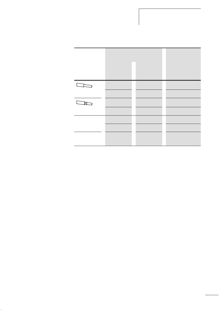
Folgende Leitungsquerschnitte sind möglich.
Page 27
05/05 AWB2300-1527D/GB
Geräte montieren
Tabelle 8: Leitungsquerschnitte
Hauptstrombahnen Hilfsstrom-
bahnen
ZB12 ZB32 95-96
97-98
1 x (1 – 6) 1 x (1– 6) 1 x (0,75 – 4)
[mm2] 2 x (1– 6) 2 x (1– 6) 2 x (0,75 – 4)
1)
1 x (1– 6) 1 x (1– 6) 1x (0,75 – 2,5)
2
] 2 x (1– 6) 2 x (1– 6) 2 x (0,75 – 2,5)
[mm
AWG 1 x (14 – 8) 1 x (14 –8) 1 x (18 – 12)
2 x (14 – 8) 2 x (14 – 8) 2 x (18 – 12)
Anzugsdreh-
1,8 1,8 1,2
moment [Nm]
1) Aderendhülse nach DIN 46228.
23
Page 28

05/05 AWB2300-1527D/GB
24
Page 29

05/05 AWB2300-1527D/GB
Einstellungen
4 Geräte betreiben
Einstellungen Vor der Erstinbetriebnahme des Motorschutzrelais muss der
Motornennstrom mit Hilfe einer Stromeinstellscheibe am
Relais eingestellt werden (a Tabelle 1 und Tabelle 2,
Seite 8).
Vorsicht!
i
Bei einem kühlen Aufstellungsort des Motorschutzrelais
(z. B. -5 °C) und einem warmen Aufstellungsort des
Motors (z. B. 40 °C) kann es im Überlastfall zu einer verzögerten Auslösung kommen, wenn die Geräte im unteren
Stromeinstellbereich betrieben werden.
Rücksetzung
Die Motorschutzrelais ZB12 und ZB32 bieten mit Hilfe des
Wahlknopfes Reset die Möglichkeit, zwischen einem automatischem Wiederanlauf „A“ und einer Handrücksetzung
„H“ zu wählen.
H
A
Abbildung 10: Schaltmöglichkeiten mit Wahlknopf Reset
Die Stellung „H“ verhindert einen automatischen Wiederanlauf und ist werksseitig bei den Motorschutzrelais vorgewählt. In der Stellung „H“ muss das Relais nach einer
Auslösung händisch durch Drücken dieses Wahlknopfes
zurückgesetzt werden.
25
Page 30

Geräte betreiben
05/05 AWB2300-1527D/GB
Test
Die Motorschutzrelais ZB12 und ZB32 sind mit einer Taste
Test versehen, in der eine Doppelfunktion integriert ist.
OFF
TEST
Abbildung 11: Schaltmöglichkeiten der Taste Test
Ein Drücken der Taste hat das Öffnen des Hilfskontaktes
95-96 zur Folge und kann zum Abschalten des Schützes
genutzt werden.
Im stromlosen Zustand kann durch das Drücken der Taste die
Funktion beider Hilfsschalter getestet werden.
NC 95
NO 97
NC 96
NO 98
26
j
Warnung!
Funktionsuntüchtige Geräte dürfen nicht geöffnet und
repariert werden. Sie müssen von Fachpersonal ausgetauscht werden.
Page 31

05/05 AWB2300-1527D/GB
Contents
About this manual 29
Target group 29
Abbreviations and symbols 29
Modification index 30
1 ZB12 and ZB 32 overload relays 31
Preface 31
Overview of the devices 31
Device description 32
– Overload protection relays with
bimetallic release 32
– Current ranges of the motor-protective relays 33
– Temperature compensation 35
– Phase loss 35
–Reset 36
– Test function 37
2 Configuration 39
Monitoring overload of motors in the EEx e area 39
Adjusting the overload current protection 39
– Short-circuit protection of the
motor-protective relays 40
Approvals 43
3 Installation 45
Notes on installation 45
Mounting the devices 47
4 Operating the devices 51
Settings 51
–Reset 51
–Test 52
27
Page 32

Contents
05/05 AWB2300-1527D/GB
Anhang/Appendix 53
Typenschilder/Rating plates 53
– Motorschutzrelais/Overload relay ZB12
und/and ZB32 53
Auslösekennlinien/
Tripping characteristics 55
– ZB12-0,16 und/and ZB32-0,16 56
– ZB12-0,24 und/and ZB32-0,24 58
– ZB12-0,4 und/and ZB32-0,4 60
– ZB12-0,6 und/and ZB32-0,6 62
– ZB12-1 und/and ZB32-1 64
– ZB12-1,6 und/and ZB32-1,6 66
– ZB12-2,4 und/and ZB32-2,4 68
– ZB12-4 und/and ZB32-4 70
– ZB12-6 und/and ZB32-6 72
– ZB12-10 und/and ZB32-10 74
– ZB12-12 76
– ZB12-16 78
– ZB32-16 80
– ZB32-24 82
– ZB32-32 84
Konformitätserklärung/Declaration
of Conformity 86
28
Page 33

05/05 AWB2300-1527D/GB
About this manual
This manual applies to the motor-protective relays ZB12 and
ZB32.
It describes the overload monitoring system for the
protection of motors operating in potentially explosive
atmospheres EEx e areas.
Target group This manual addresses special personnel who install,
commission and service the motor-protective relay.
Abbreviations and symbols
h
h
i
The abbreviations and symbols used in this manual have the
following meaning:
EEx e "Increased safety“ type of protection
PTB Physikalisch Technische Bundesanstalt. German
Federal Testing Laboratory: Accredited certification
authority for devices operated in EEx e areas.
NM Lowest possible setup current
HM Highest possible setup current
X indicates actions to be taken.
Draws our attention towards interesting tips and
additional information
Note!
Warns of a hazardous situation that could result in
damage to the product or components.
Caution!
Warns of the possibility of a hazardous situation that
could result in major damage and minor injury.
29
Page 34

About this manual
Modification index
j
05/05 AWB2300-1527D/GB
Warning!
Warns of the risk of heavy material damage and of serious
or lethal injury.
The chapter title in the header on the left side and the title
of the current topic on the right side provide you with a good
overview of this documentation. Exceptions are the starting
pages of the chapters and empty pages at the end of a
chapter.
Edition
date
05/05 32 section “Direct mounting” j
Page Subject New Modi-
fied
34 table 1 „ZB12 relay current ranges“ j
35 section “Temperature compensation” j
41 table 3 „ZB12 direct mounting“ j
42 table 4 „Direct mounting or individual
installation of the ZB32“
47 table 5 „Direct mounting“ j
54 table 9 „Values of the various types“ j
78 Tripping characteristic „ZB12-16“ j
j
Omitted
30
Page 35

05/05 AWB2300-1527D/GB
1 ZB12 and ZB 32 overload relays
Preface In addition to the type of protection specified in the
standards EN 60079-14 and VDE 0165 Part 1, further
provisions have been made to ensure the safety from ignition
for motors operated in potentially explosive atmospheres.
EN 50019 demands additional measures for operating
motors with "increased safety" type of protection "e".
These measures provide a higher degree of safety and
prevent impermissible high temperature and development of
sparking and arcing on the motors, which usually does not
occur under normal operating conditions. The motor
protective equipment used for this is operated at a location
separate from the EEx e area and must be certified by an
accredited certification authority.
The guidelines on the application of Directive 94/9/EC (ATEX
100a) on the approximation of the laws of the Member
States concerning equipment and protective systems
intended for use in potentially explosive atmospheres has
been enforced since 30
th
June 2003.
Overview of the devices
The motor-protective relays ZB12 and ZB32 are certified by
PTB according to the 94/9/EC (ATEX 100a) Directives.
a The EU Certification of Conformity numbers are:
ZB12: PTB 04 ATEX 3022
ZB32: PTB 04 ATEX 3022
Figure 1: ZB12 overload relay
31
Page 36

ZB12 and ZB 32 overload relays
Figure 2: ZB32 overload relay
05/05 AWB2300-1527D/GB
Device description Overload protection relays with bimetallic release
The overload relays ZB12 and ZB32 are 3-pole
electromechanical motor-protective relays and are equipped
with bimetallic releases. They are suitable for monitoring
direct (DC) and alternating (AC) current.
The ZB12 and ZB32 overload relays can be mounted directly
on the DIL contactors.
Direct mounting
Motor-protective relay Contactor relay
32
ZB12 DILM7
DILM9
DILM12
DILM15
ZB32
DILM17
DILM25
DILM32
Furthermore, the ZB32 relay can be used individually in
combination with an individual mounting.
Individual mounting
Motor-protective relay Individual mounting
ZB32 ZB32-XEZ
In the event of overload tripping, the auxiliary contacts
95-96 and 97-98 change over and disconnect the control
voltage circuit from the corresponding contactor relay, and
Page 37

05/05 AWB2300-1527D/GB
Device description
thus indirectly switch off the current flow to the monitored
motor.
L1
(Q11/1)
-F0
95
-F2
96
21
0
22
-S11
13
I
14
14
-Q11
13
A1
-Q11
A2
N
Q11
F1
F2
L1 L2 L3
135
246
246
UVW
979795
96
PE
M
3~
M1
Figure 3: Circuit diagram of a motor tap with motor-protective
relay
F1 Fuse
F2 Motor-protective relay
K1M Motor contactor
M1 Motor
Current ranges of the motor-protective relays
The rated motor current is set on the Z relays by means of a
current setting dial.
The various types can be used to monitor motors operating
at a rated current of 0.1 to 32 A.
33
Page 38

ZB12 and ZB 32 overload relays
05/05 AWB2300-1527D/GB
Table 1: ZB12 relay current ranges
34
Type
ZB12-0,16 0.1 to 0.16
ZB12-0,24 0.16 to 0.24
ZB12-0,4 0.24 to 0.4
ZB12-0,6 0.4 to 0.6
ZB12-1,0 0.6 to 1.0
ZB12-1,6 1.0 to 1.6
ZB12-2,4
ZB12-4 2.4 to 4.0
ZB12-6 4.0 to 6.0
ZB12-10 6.0 to 10
ZB12-12 9 to 12
ZB12-16 12 to 16
Table 2: ZB32 relay current ranges
Type
ZB32-0,16 0.1 to 0.16
ZB32-0,24 0.16 to 0.24
ZB32-0,4 0.24 to 0.4
ZB32-0,6 0.4 to 0.6
ZB32-1,0 0.6 to 1.0
ZB32-1,6 1.0 to 1.6
ZB32-2,4 1.6 to 2.4
ZB32-4
ZB32-6 4.0 to 6.0
ZB32-10 6.0 to 10
ZB32-16 10 to 16
ZB32-24 16 to 24
ZB32-32 24 to 32
Current range I [A]
1.6 to 2.4
Current range I [A]
2.4 to 4.0
Page 39

05/05 AWB2300-1527D/GB
Device description
Temperature compensation
Two parameters influence the deflection of the bimetallic
releases. There is for one the heat which is generated in
proportion to the current flow, and secondly, the influence of
the ambient temperature.
The influence of the ambient temperature is automatically
compensated within a temperature range from -5 °C to
+55 °C by means of an additional current-free bimetallic
release that continuously corrects the tripping range.
Phase loss
ZB12 and ZB32 overload relays are single-phasing sensitive.
The deflecting action of all three bimetallic releases is
directed towards a tripping bridge that switches over a
quick-break switch when the limit value is reached. At the
same time, all three bimetallic releases shift the differential
bridge. If the path of action of one of the bimetallic releases
is reduced due to a phase loss, the differential bridge is
retarded and the distance is converted into an additional
tripping distance, which leads to an early tripping.
햲
햳
Normal error-free
operation
Figure 4: Function of the phase sensitivity by means of tripping
a Tripping bridge
b Differential bridge
c Differential distance
s = Tripping distance
햴
97S95
98 96
97 95
98 96
3-phase overload Failure of one phase
(two-phase load)
and differential bridge
97 95
98 96
35
Page 40

ZB12 and ZB 32 overload relays
05/05 AWB2300-1527D/GB
h
When a ZB12 or ZB32 relay is to be used for monitoring an
AC or DC motor, the current must flow across all three
current paths in order to avoid early tripping.
Figure 5: Wiring of the motor-protective relay for the protection of
AC or DC motors (bimetallic release switched in series)
(a Section "Tripping characteristics" as of page 53)
Reset
After tripping, the bimetallic releases must first cool down
before the motor-protective relay can be reset. Manual and
automatic reset can be selected by means of a selector
switch (a section “Reset”to page 51).
In auto mode, the contacts automatically fall back after the
bimetallic releases have cooled down, whereas in manual
mode the tripping must be acknowledged locally on the
motor-protective relay.
36
j
Warning!
To ensure explosion-proof operation, the motor-protective
relay may only be reset/switched on manually, or
automatically via a control interlock circuit for the motor
or electrical machinery, after the bimetallic release has
cooled down.
A manual reset may be carried out by trained personnel
locally or in the control room.
Page 41

05/05 AWB2300-1527D/GB
Device description
Test function
The function of the auxiliary contacts can be verified by
means of an additional test button that has a dual function:
• Pressing the test button will open the break contact (NC)
95-96. The open contact will return to the closed position
as soon as the button is released.
This function can also be used to switch off the motor
manually.
• Pulling the button will trip the motor-protective relay. The
break contact 95-96 opens and the make contact 97-98
closes. After the test button is released, the motorprotective relay must be reset in the same way as after a
normal tripping (a section “Reset”to page 36).
37
Page 42

05/05 AWB2300-1527D/GB
38
Page 43

05/05 AWB2300-1527D/GB
2 Configuration
Monitoring overload of motors in the EEx e area
Adjusting the overload current protection
j
EEx e type of protection is achieved on motors by special
constructive measures. The motors are assigned according to
the highest permissible surface temperature classes. The
temperature rise time t
current and rated current I
specified on the rating plate of the motor.
The temperature rise time t
for the temperature of the motor winding to rise from its final
rated operational temperature up to the limit temperature,
at a startup current of I
However, since EEx e motors are not intrinsically safe,
explosion safety is only achieved by taking special measures
during installation and by selecting appropriate operating
conditions (PTB testing regulations), e.g. by a combination
of the circuit with a correctly rated and set overload current
protection.
Warning!
The selected current overload protection system must not
only ensure proper motor current monitoring, but also that
the seized motor is switched off within the temperature
rise time t
rated in such a way to ensure that the tripping time
the ratio
temperature rise time
curve, in order to safely switch off the motor within that
period (
. This means, the protective device must be
E
I
A/IN
a following example).
and the ratio between startup
E
are calculated also and
A/IN
represents the time that expires
E
t.
A
t
A
of the EEx e motor is not higher than its
t
according to its characteristics
E
for
39
Page 44

Configuration
Example: IA/IN = 6, tE = 10 s
10
J
8
6
4
min
2
1
40
20
10
8
6
4
s
2
1
0.8
0.6
0.4
05/05 AWB2300-1527D/GB
40
i
0.2
0.1
1
2345678910
N
1
Figure 6: Tripping characteristics of the motor-protective relay
The motor is reliably protected.
Short-circuit protection of the motor-protective relays
The motor-protective relays are short-circuit protected by
means of fuses. When the relay is mounted directly onto a
contactor relay, the corresponding primary fuse of the
contactor relay is taken into account accordingly.
Caution!
Only co-ordination type “2” is permissible for the
protection of EEx e motors.
Page 45

05/05 AWB2300-1527D/GB
Contactor
relay
Adjusting the overload current
protection
Table 3: ZB12 direct mounting
Fuse gG/gL [A] Rated short-circuit
Type of
assignment "1"
Type of
1)
assignment "2"
1)
current
Iq [kA]
ZB12-0,16 DILM7
ZB12-0,24 1
ZB12-0,4 2
DILM9
DILM12
DILM15
25 0.5 100
ZB12-0,6 4
ZB12-1,0 4
ZB12-1,6 6
ZB12-2,4 10
ZB12-4 16
ZB12-6
20
ZB12-10 50 25
ZB12-12 50 25
ZB12-16
50 25
1) to IEC/EN 60947
41
Page 46

Configuration
Contactor
relay
05/05 AWB2300-1527D/GB
Table 4: Direct mounting or individual installation of the ZB32
Fuse gG/gL [A]
Type of
assignment "1"
Type of
1)
assignment "2"
1)
ZB32-0,16 DILM17
ZB32-0,24 1
DILM25
DILM32
25 0.5 100
ZB32-0,4 2
ZB32-0,6 4
ZB32-1,0 4
ZB32-1,6 6
ZB32-2,4 10
ZB32-4 16
ZB32-6
20
ZB32-10 50 25
ZB32-16 63 35
ZB32-24
100 35
ZB32-32 125 63
1) to IEC/EN 60947
42
Page 47

05/05 AWB2300-1527D/GB
Approvals The ZB12 and ZB32 overload relays are manufactured
conform to the IEC EN 60947 low-voltage switchgear
standards and comply with the demands of the
94/9/EC (ATEX 100a) directive for the protection of
EEx e-motors.
Furthermore, motors in zones 21 and 22 (areas with
combustible dusts) can be protected conform to
EN 50281-1-1 and EN 50281-1-2. The motor outgoer wiring
must be implemented conform to IEC/EN 60947-1, table 9.
Approvals
c
0102
ZB12: PTB 04 ATEX 3022
ZB32: PTB 04 ATEX 3022
The relays are approved by UL and CSA for the USA and
Canada.
II(2)GD
Us
Further approvals exist for
• China
43
Page 48

05/05 AWB2300-1527D/GB
44
Page 49

05/05 AWB2300-1527D/GB
Notes on installation
3 Installation
Notes on installation The mechanical and electrical installation instructions must
be observed. The installation instructions are printed on the
inside of the cardboard packaging.
ZB12, ZB32: AWA2300-2114
Warning!
j
To ensure explosion-proof operation, the motor-protective
relay may only be reset/switched on manually, or
automatically via a control interlock circuit for the motor
or electrical machinery, after the bimetallic release has
cooled down.
A manual reset may be carried out by trained personnel
locally or in the control room.
j
Warning!
Particularly in EEx e applications, an automatic restart
must be prevented after an interruption of the control
voltage. This is prevented safely by means of the latching
function of the power relay.
45
Page 50

Installation
05/05 AWB2300-1527D/GB
L1 L2 L3
Q11
F1
F2
135
246
246
UVW
979795
96
PE
-F2
0
-S11
I
-Q11
N
M
3~
M1
Figure 7: The circuit prevents an automatic restart.
F1 Fuse
F2 Motor-protective relay
K1M Contactor relay
M1 Motor
L1
(Q11/1)
95
96
21
22
13
14
-Q11
A1
A2
-F0
14
13
46
The latching function of the K1M contactor relay prevents an
automatic restart.
Page 51

05/05 AWB2300-1527D/GB
Mounting the devices
Mounting the devices The ZB12 and ZB32 overload relays can be mounted directly
on the contactor.
The ZB32 can additionally be used in combination with an
individual mounting.
Table 5: Direct mounting
Contactor relay
DILM7, DILM9, DILM12, DILM15 ZB12-...
DILM17, DILM25, DILM32 ZB32-...
Table 6: Individual installation
Motor-protective relay
Motor-protective relay
ZB32-... ZB32-XEZ
X Mount the devices as shown in the figures below.
ZB12, ZB32
Figure 8: Mounting ZB12, ZB32
Individual mounting
ZB32
ZB32-XEZ
47
Page 52

Installation
05/05 AWB2300-1527D/GB
The individually mounted ZB32-XEZ can be mounted on a
top-hat rail or directly on a mounting plate.
Table 7: Mounting dimensions
ZB32-XEZ
Bore dimensions (W x H)
[mm]
Screw [mm]
X Wire the motor cables
1h/H 3 ~
Figure 9: Mains wiring
35 x 75
2 x (M4 x 12)
The following conductor cross-sections can be used.
48
Page 53

05/05 AWB2300-1527D/GB
Mounting the devices
Table 8: Conductor cross-sections
Mains circuit Auxiliary
voltage circuit
ZB12 ZB32 95-96
97-98
1 x (1– 6) 1 x (1– 6) 1 x (0.75 – 4)
[mm2] 2 x (1– 6) 2 x (1– 6) 2 x (0.75 – 4)
1)
1 x (1– 6) 1 x (1– 6) 1x (0.75 – 2.5)
2
] 2 x (1– 6) 2 x (1– 6) 2 x (0.75 – 2.5)
[mm
AWG 1 x (14 – 8) 1 x (14 – 8) 1 x (18 – 12)
2 x (14 – 8) 2 x (14 – 8) 2 x (18 – 12)
Tightening
1.8 1.8 1.2
torque [N/m]
1) Ferrule to DIN 46228.
49
Page 54

05/05 AWB2300-1527D/GB
50
Page 55

05/05 AWB2300-1527D/GB
Settings
4 Operating the devices
Settings Prior to initial commissioning, the rated motor current must
be set on the motor-protective relay by means of the current
dial (a table 1 and table 2, page 34).
Caution!
i
If the overload relay is installed at a cool location
(e.g. -5 °C) and the motor is installed at a warm motor
location (e.g. 40 °C), it is possible that there will be a
delayed release during an overload if the devices are
operated in the lower current setting range.
Reset
The user can select automatic restart "A" or manual reset
"H" on the motor-protective relays ZB12 and ZB32 by
means of the Reset selector button.
H
A
Figure 10: Switching options of the reset selector button
The factory set position "H" on the motor-protective relay
prevents automatic restarts. In position "H", the relay must
be reset manually after it has tripped by pressing the selector
button.
51
Page 56

Operating the devices
05/05 AWB2300-1527D/GB
Test
The motor-protective relays ZB12 and ZB32 are equipped
with a test button that has an integral dual function.
OFF
TEST
Figure 11: Switching options of the test button
The auxiliary contact 95-96 is opened by pressing the
button, and can thus be used to switch off the contactor
relay.
The function of both auxiliary contacts can be tested in
current-less state by pressing the button.
NC 95
NO 97
NC 96
NO 98
52
j
Warning!
Faulty devices may not be opened for repairs and may only
be replaced suitably qualified personnel.
Page 57

05/05 AWB2300-1527D/GB
Anhang/Appendix
Typenschilder/Rating plates
Motorschutzrelais/Overload relay ZB12 und/and ZB32
AF
U
imp
U
690 V h
e
Normal
97
98
AC–15
95–96:
97–98:
U
imp
Abbildung/Figure 12: Typenschild/Rating plate ZB12 und/and
6000 V
95
96
U
I
I
6000 V
0102
e
e
e
"1"
max
"2"
Y
1
Test
95
97
98
96
220/240
1,5
1,5
380/415 500Vh
0,9 0,8 A
0,5 0,5 A
I
II(2)GD
PTB 04 ATEX 3022
IEC/EN 60947
ZB32
C
D
97
98
th
A gL
6 A
A014079
Y
2
95
96
Die Zuordnungen der Werte zu den jeweiligen Typen sind der
nachfolgenden Tabelle 9 zu entnehmen.
For information on the assignment of values to the relevant
types, please refer to Tabelle 9.
53
Page 58

Anhang/Appendix
05/05 AWB2300-1527D/GB
Tabelle/Table 9: Werte der einzelnen Typen/Values of the
various types
A
ZB12-0,16 0.1 – 0.16 A 25 0.5
ZB12-0,24 0.16 – 0.24 A 25 1
ZB12-0,4 0.24 – 0.4 A 25 2
ZB12-0,6
ZB12-1 0.6 – 1 A 25 4
ZB12-1,6 1 – 1.6 A 25 6
ZB122,4 1.6 – 2.4 A 25 10
ZB12-4 2.4 – 4 A 25 16
ZB12-6 4 – 6 A 25 20
ZB12-10 6 – 10 A 50 25
ZB12-12 9 – 12 A 50 25
ZB12-16 12 – 16 A 50 25
ZB32-0,16 0.1 – 0.16 A 25 0.5
ZB32-0,24 0.16 – 0.24 A 25 1
ZB32-0,4 0.24 – 0.4 A 25 2
ZB32-0,6
ZB32-1 0.6 – 1 A 25 4
ZB32-1,6 1 – 1.6 A 25 6
ZB322,4 1.6 – 2.4 A 25 10
ZB32-4 2.4 – 4 A 25 16
ZB32-6 4 – 6 A 25 20
ZB32-10 6 – 10 A 50 25
ZB32-16 10 - 16 A 63 35
ZB32-24 16 - 24 A 100 35
ZB32-32 24 - 32 A 125 63
F C D
0.4 – 0.6 A 25 4
0.4 – 0.6 A 25 4
54
Page 59

05/05 AWB2300-1527D/GB
Auslösekennlinien/ Tripping characteristics
Auslösekennlinien/ Tripping
characteristics
55
Page 60

Anhang/Appendix
05/05 AWB2300-1527D/GB
ZB12-0,16 und/and ZB32-0,16
Bereich/Range 0.1 – 0.16 A (NM – HM)
Umgebungstemperatur/Ambient temperature
Auslöseklasse/Tripping class
Toleranzbereich/Tolerance range
20 °C
10 A
g 20 %
Einstellung/
Setting
3 x I 23 17.5 21 14
7.2 x I 5.5 4.6 5.2 4.0
Auslösezeit/Tripping time t [s]
NM HM
3-phase a 2-phase c 3-phase b 2-phase d
56
Page 61

05/05 AWB2300-1527D/GB
1000
500
100
Auslösekennlinien/ Tripping
characteristics
0.5
50
b
a
10
c
5
1
d
0.1
1
2345678910
Abbildung/Figure 13: ZB12-0,16 und/and ZB32-0,16
57
Page 62

Anhang/Appendix
05/05 AWB2300-1527D/GB
ZB12-0,24 und/and ZB32-0,24
Bereich/Range 0.16 – 0.24 A (NM – HM)
Umgebungstemperatur/Ambient temperature
Auslöseklasse/Tripping class
Toleranzbereich/Tolerance range
20 °C
10 A
g 20 %
Einstellung/
Setting
3 x I 21 15 21 13.5
7.2 x I 5.1 4 5.1 3.6
Auslösezeit/Tripping time t [s]
NM HM
3-phase a 2-phase c 3-phase b 2-phase d
58
Page 63

05/05 AWB2300-1527D/GB
1000
500
100
50
a
Auslösekennlinien/ Tripping
characteristics
b
10
0.5
0.1
c
5
1
1
2345678910
Abbildung/Figure 14: ZB12-0,24 und/and ZB32-0,24
d
59
Page 64

Anhang/Appendix
05/05 AWB2300-1527D/GB
ZB12-0,4 und/and ZB32-0,4
Bereich/Range 0.24 – 0.4 A (NM – HM)
Umgebungstemperatur/Ambient temperature
Auslöseklasse/Tripping class
Toleranzbereich/Tolerance range
20 °C
10 A
g 20 %
Einstellung/
Setting
3 x I 23.5 18 22 13.5
7.2 x I 5.9 4.8 5.5 4.0
Auslösezeit/Tripping time t [s]
NM HM
3-phase a 2-phase c 3-phase b 2-phase d
60
Page 65

05/05 AWB2300-1527D/GB
1000
500
100
Auslösekennlinien/ Tripping
characteristics
50
10
0.5
a
b
c
5
1
d
0.1
1
2345678910
Abbildung/Figure 15: ZB12-0,4 und/and ZB32-0,4
61
Page 66

Anhang/Appendix
05/05 AWB2300-1527D/GB
ZB12-0,6 und/and ZB32-0,6
Bereich/Range 0.4 – 0.6 A (NM – HM)
Umgebungstemperatur/Ambient temperature
Auslöseklasse/Tripping class
Toleranzbereich/Tolerance range
20 °C
10 A
g 20 %
Einstellung/
Setting
3 x I 27 19.5 25 15.5
7.2 x I 6.5 5.4 6.2 4.6
Auslösezeit/Tripping time t [s]
NM HM
3-phase a 2-phase c 3-phase b 2-phase d
62
Page 67

05/05 AWB2300-1527D/GB
1000
500
100
Auslösekennlinien/ Tripping
characteristics
50
10
0.5
a
b
c
5
1
d
0.1
1
2345678910
Abbildung/Figure 16: ZB12-0,6 und/and ZB32-0,6
63
Page 68

Anhang/Appendix
05/05 AWB2300-1527D/GB
ZB12-1 und/and ZB32-1
Bereich/Range 0.6 – 1 A (NM – HM)
Umgebungstemperatur/Ambient temperature
Auslöseklasse/Tripping class
Toleranzbereich/Tolerance range
20 °C
10 A
g 20 %
Einstellung/
Setting
3 x I 29.4 22 26 15
7.2 x I 7.3 5.9 6.5 4.6
Auslösezeit/Tripping time t [s]
NM HM
3-phase a 2-phase c 3-phase b 2-phase d
64
Page 69

05/05 AWB2300-1527D/GB
1000
500
100
Auslösekennlinien/ Tripping
characteristics
50
10
0.5
a
b
c
5
1
d
0.1
1
2345678910
Abbildung/Figure 17: ZB12-1 und/and ZB32-1
65
Page 70

Anhang/Appendix
05/05 AWB2300-1527D/GB
ZB12-1,6 und/and ZB32-1,6
Bereich/Range 1 – 1.6 A (NM – HM)
Umgebungstemperatur/Ambient temperature
Auslöseklasse/Tripping class
Toleranzbereich/Tolerance range
20 °C
10 A
g 20 %
Einstellung/
Setting
3 x I 29 20 27 16
7.2 x I 6.9 5.5 6.5 4.4
Auslösezeit/Tripping time t [s]
NM HM
3-phase a 2-phase c 3-phase b 2-phase d
66
Page 71

05/05 AWB2300-1527D/GB
1000
500
100
Auslösekennlinien/ Tripping
characteristics
50
10
0.5
a
b
c
5
1
d
0.1
1
2345678910
Abbildung/Figure 18: ZB12-1,6 und/and ZB32-1,6
67
Page 72

Anhang/Appendix
05/05 AWB2300-1527D/GB
ZB12-2,4 und/and ZB32-2,4
Bereich/Range 1.6 – 2.4 A (NM – HM)
Umgebungstemperatur/Ambient temperature
Auslöseklasse/Tripping class
Toleranzbereich/Tolerance range
20 °C
10 A
g 20 %
Einstellung/
Setting
3 x I 28.5 19 25 15.3
7.2 x I 6.8 5.3 6.3 4.7
Auslösezeit/Tripping time t [s]
NM HM
3-phase a 2-phase c 3-phase b 2-phase d
68
Page 73

05/05 AWB2300-1527D/GB
1000
500
100
Auslösekennlinien/ Tripping
characteristics
50
10
0.5
a
b
c
5
1
d
0.1
1
2345678910
Abbildung/Figure 19: ZB12-2,4 und/and ZB32-2,4
69
Page 74

Anhang/Appendix
05/05 AWB2300-1527D/GB
ZB12-4 und/and ZB32-4
Bereich/Range 2.4 – 4 A (NM – HM)
Umgebungstemperatur/Ambient temperature
Auslöseklasse/Tripping class
Toleranzbereich/Tolerance range
20 °C
10 A
g 20 %
Einstellung/
Setting
3 x I 32.1 24 30 17.9
7.2 x I 7.8 6.5 7.3 5.2
Auslösezeit/Tripping time t [s]
NM HM
3-phase a 2-phase c 3-phase b 2-phase d
70
Page 75

05/05 AWB2300-1527D/GB
1000
500
100
Auslösekennlinien/ Tripping
characteristics
50
10
0.5
a
b
c
5
1
d
0.1
1
2345678910
Abbildung/Figure 20: ZB12-4 und/and ZB32-4
71
Page 76

Anhang/Appendix
05/05 AWB2300-1527D/GB
ZB12-6 und/and ZB32-6
Bereich/Range 4 – 6 A (NM – HM)
Umgebungstemperatur/Ambient temperature
Auslöseklasse/Tripping class
Toleranzbereich/Tolerance range
20 °C
10 A
g 20 %
Einstellung/
Setting
3 x I 32.5 24.5 30 19.2
7.2 x I 7.4 6 6.9 5
Auslösezeit/Tripping time t [s]
NM HM
3-phase a 2-phase c 3-phase b 2-phase d
72
Page 77

05/05 AWB2300-1527D/GB
1000
500
100
Auslösekennlinien/ Tripping
characteristics
50
10
0.5
a
b
c
5
1
d
0.1
1
2345678910
Abbildung/Figure 21: ZB12-6 und/and ZB32-6
73
Page 78

Anhang/Appendix
05/05 AWB2300-1527D/GB
ZB12-10 und/and ZB32-10
Bereich/Range 6 – 10 A (NM – HM)
Umgebungstemperatur/Ambient temperature
Auslöseklasse/Tripping class
Toleranzbereich/Tolerance range
20 °C
10 A
g 20 %
Einstellung/
Setting
3 x I 33.5 23.7 31 19
7.2 x I 7 5.3 6.2 4.4
Auslösezeit/Tripping time t [s]
NM HM
3-phase a 2-phase c 3-phase b 2-phase d
74
Page 79

05/05 AWB2300-1527D/GB
1000
500
100
50
Auslösekennlinien/ Tripping
characteristics
a
b
10
0.5
0.1
c
5
1
1
2345678910
Abbildung/Figure 22: ZB12-10 und/and ZB32-10
d
75
Page 80

Anhang/Appendix
05/05 AWB2300-1527D/GB
ZB12-12
Bereich/Range 9 – 12 A (NM – HM)
Umgebungstemperatur/Ambient temperature
Auslöseklasse/Tripping class
Toleranzbereich/Tolerance range
20 °C
10 A
g 20 %
Einstellung/
Setting
3 x I 30.7 18.8 27.2 15.7
7.2 x I 6.1 4.1 5.6 3.6
Auslösezeit/Tripping time t [s]
NM HM
3-phase a 2-phase c 3-phase b 2-phase d
76
Page 81

05/05 AWB2300-1527D/GB
1000
500
100
Auslösekennlinien/ Tripping
characteristics
50
10
0.5
a
b
c
5
1
d
0.1
1
2345678910
Abbildung/Figure 23: ZB12-12
77
Page 82

Anhang/Appendix
05/05 AWB2300-1527D/GB
ZB12-16
Bereich/Range 12 – 16 A (NM – HM)
Umgebungstemperatur/Ambient temperature
Auslöseklasse/Tripping class
Toleranzbereich/Tolerance range
20 °C
10 A
g 20 %
Einstellung/
Setting
3 x I 30 24 29 19
7.2 x I 4.3 3.6 4.1 3
Auslösezeit/Tripping time t [s]
NM HM
3-phase a 2-phase c 3-phase b 2-phase d
78
Page 83

05/05 AWB2300-1527D/GB
1000
100
a
Auslösekennlinien/ Tripping
characteristics
b
10
0.1
c
d
1
1
Abbildung/Figure 24: ZB12-16
2345678910
79
Page 84

Anhang/Appendix
05/05 AWB2300-1527D/GB
ZB32-16
Bereich/Range 10 – 16 A (NM – HM)
Umgebungstemperatur/Ambient temperature
Auslöseklasse/Tripping class
Toleranzbereich/Tolerance range
20 °C
10 A
g 20 %
Einstellung/
Setting
3 x I 30 22 28 16.4
7.2 x I 4.1 3.2 3.8 2.4
Auslösezeit/Tripping time t [s]
NM HM
3-phase a 2-phase c 3-phase b 2-phase d
80
Page 85

05/05 AWB2300-1527D/GB
1000
500
100
Auslösekennlinien/ Tripping
characteristics
50
10
0.5
a
b
c
5
1
d
0.1
1
2345678910
Abbildung/Figure 25: ZB32-16
81
Page 86

Anhang/Appendix
05/05 AWB2300-1527D/GB
ZB32-24
Bereich/Range 16 – 24 A (NM – HM)
Umgebungstemperatur/Ambient temperature
Auslöseklasse/Tripping class
Toleranzbereich/Tolerance range
20 °C
10 A
g 20 %
Einstellung/
Setting
3 x I 34.5 24.5 30 19
7.2 x I 6.3 4.9 5.6 4
Auslösezeit/Tripping time t [s]
NM HM
3-phase a 2-phase c 3-phase b 2-phase d
82
Page 87

05/05 AWB2300-1527D/GB
1000
500
100
Auslösekennlinien/ Tripping
characteristics
50
10
0.5
a
b
c
5
1
d
0.1
1
2345678910
Abbildung/Figure 26: ZB32-24
83
Page 88

Anhang/Appendix
05/05 AWB2300-1527D/GB
ZB32-32
Bereich/Range 24 – 32 A (NM – HM)
Umgebungstemperatur/Ambient temperature
Auslöseklasse/Tripping class
Toleranzbereich/Tolerance range
20 °C
10 A
g 20 %
Einstellung/
Setting
3 x I 30.2 21.8 26.6 17.8
7.2 x I 6.1 4.7 5.4 3.9
Auslösezeit/Tripping time t [s]
NM HM
3-phase a 2-phase c 3-phase b 2-phase d
84
Page 89

05/05 AWB2300-1527D/GB
1000
500
100
Auslösekennlinien/ Tripping
characteristics
50
10
0.5
a
b
c
5
1
d
0.1
1
2345678910
Abbildung/Figure 27: ZB32-32
85
Page 90

Anhang/Appendix
Konformitätserklärung/Declaration of Conformity
05/05 AWB2300-1527D/GB
86
Page 91

Moeller GmbH
Industrieautomation
Hein-Moeller-Straße 7–11
D-53115 Bonn
E-Mail: info@moeller.net
Internet: www.moeller.net
© 2002 by Moeller GmbH
Subjekt to alteration
AWB2300-1527D/GB Doku/Doku/Eb 05/05
Printed in the Federal Republic of Germany (09/05)
Article No.: 284910
4 *patpks#,v.y-,*
A A
Think future. Switch to green. Think future. Switch to green.
 Loading...