

Page 1
Building Automation
Device Description
Embedded HMI
XVH-3x0
01/05 AWB2776-1559GB
SystemsIndustrial Automation
Page 2

All brand and product names are trademarks or registered
trademarks of the owner concerned.
st
1
published 2005, edition date 01/05
© Moeller GmbH, 53105 Bonn
Author:Peter Zuber
Production: Norbert Mausolf
All rights reserved, including those of the translation.
No part of this manual may be reproduced in any form
(printed, photocopy, microfilm or any other process) or processed,
duplicated or distributed by means of electronic systems without
written permission of Moeller GmbH, Bonn.
Subject to alteration without notice.
Page 3

Warning!
Dangerous electrical voltage!
Before commencing the installation
• Disconnect the power supply of the device.
• Ensure that devices cannot be accidentally restarted.
• Verify isolation from the supply.
• Earth and short circuit.
• Cover or enclose neighbouring units that are live.
• Follow the engineering instructions (AWA) of the
device concerned.
• Only suitably qualified personnel in accordance with
EN 50110-1/-2 (VDE 0105 Part 100) may work on
this device/system.
• Before installation and before touching the device ensure
that you are free of electrostatic charge.
• The functional earth (FE) must be connected to the protective
earth (PE) or to the potential equalisation. The system installer
is responsible for implementing this connection.
• Connecting cables and signal lines should be installed so
that inductive or capacitive interference does not impair the
automation functions.
• Install automation devices and related operating elements in
such a way that they are well protected against unintentional
operation.
• Suitable safety hardware and software measures should be
implemented for the I/O interface so that a line or wire
breakage on the signal side does not result in undefined
states in the automation devices.
• Ensure a reliable electrical isolation of the low voltage for the
24 volt supply. Only use power supply units complying with
IEC 60364-4-41 (VDE 0100 Part 410) or HD 384.4.41 S2.
• Deviations of the mains voltage from the rated value must
not exceed the tolerance limits given in the specifications,
otherwise this may cause malfunction and dangerous
operation.
• Emergency stop devices complying with IEC/EN 60204-1 must
be effective in all operating modes of the automation devices.
Unlatching the emergency-stop devices must not cause restart.
• Devices that are designed for mounting in housings or control
cabinets must only be operated and controlled after they have
been installed with the housing closed. Desktop or portable
units must only be operated and controlled in enclosed
housings.
• Measures should be taken to ensure the proper restart of
programs interrupted after a voltage dip or failure. This should
not cause dangerous operating states even for a short time.
If necessary, emergency-stop devices should be implemented.
• Wherever faults in the automation system may cause
damage to persons or property, external measures must be
implemented to ensure a safe operating state in the event of
a fault or malfunction (for example, by means of separate limit
switches, mechanical interlocks etc.).
Moeller GmbH
Safety instructions
I
Page 4

II
Page 5

Hardware Device Description Embedded HMI XVH-3x0
Notes
01/05 AWB2776-1559GB
© by Moeller GmbH
3
Page 6

Device Description Embedded HMI XVH-3x0 Hardware
Contents
Contents
1 Explanation of Symbols ..................................................................................... 5
2 Introduction......................................................................................................... 6
2.1 Benefits of the XVH-330/340-57 Systems...............................................................6
2.2 Aim and purpose of this document..........................................................................7
2.3 List of documents .................................................................................................... 7
3 Device Versions .................................................................................................. 8
3.1 Scope of delivery..................................................................................................... 8
3.2 Options.................................................................................................................... 8
4 Commissioning ................................................................................................... 9
4.1 Overview of the terminals........................................................................................ 9
4.2 General notes on cabling....................................................................................... 10
4.3 Connection to the power supply............................................................................ 10
4.4 Ethernet................................................................................................................. 11
4.5 USB device............................................................................................................ 12
4.6 Expansion module interfaces (ComModule) optional............................................ 13
4.6.1 CAN............................................................................................................................13
4.6.2 MPI.............................................................................................................................14
5 System Control Button (CTRL)........................................................................ 15
6 System settings ................................................................................................ 16
7 CompactFlash Slot ........................................................................................... 17
8 Expansion and Configuration Options ........................................................... 18
8.1 Device interventions ..............................................................................................18
9 Function and Control LEDs.............................................................................. 19
10 Mounting Instructions ...................................................................................... 21
10.1 General mounting instructions............................................................................ 21
10.2 Standard front..................................................................................................... 22
10.3 Mechanical dimensions......................................................................................23
10.4 Front panel cutout standard front....................................................................... 24
11 Notes on the Touch Screen.............................................................................. 25
11.1 Infra-Red Touch ................................................................................................. 25
11.2 Resistive Touch.................................................................................................. 26
12 Display Technology, Backlight........................................................................ 27
13 Maintenance and Repair................................................................................... 28
14 Disposal............................................................................................................. 29
15 Technical Data................................................................................................... 30
16 EU Conformity/Safety ....................................................................................... 32
16.1 EMC ................................................................................................................... 32
16.2 Explosion protection...........................................................................................32
16.2.1 Zone 22, Category 3D ............................................................................................. 32
17 Safety / North American Approvals................................................................. 33
4
01/05 AWB2776-1559GB
© by Moeller GmbH
Page 7
Hardware Device Description Embedded HMI XVH-3x0
Explanation of Symbols
1 EXPLANATION OF SYMBOLS
Danger warnings
The following information is for your personal safety and the prevention of damage to the product
described or connected devices.
Safety instructions and warnings for the prevention of danger to the life and health of users or service
personnel, and for the prevention of damage are highlighted in this document by the following
pictograms. “Warning” and “Information” pictograms are shown in this document.
Warnings indicate the following:
Death, serious injury or substantial material damage may occur if the related safety measures are not
implemented.
The individual “Warning” pictograms have the following meaning:
Caution! General!
Is an instruction that must be strictly observed in order to protect oneself and the
device from hazards relating to the operation of the device and to ensure the proper
use of the device.
Caution! Dangerous voltage!
There is a danger of electric shock if a live part is touched.
Caution! Observe ESD measures!
Electrostatic discharge may damage or destroy electronic components.
Information pictograms indicate the following:
Important information about the product or the relevant section of the document, requiring the
particular attention of the reader.
The “Information” pictogram has the following meaning:
Indicates important and instructional information.
01/05 AWB2776-1559GB
© by Moeller GmbH
5
Page 8

Device Description Embedded HMI XVH-3x0 Hardware
Introduction
2 INTRODUCTION
2.1 BENEFITS OF THE XVH-330/340-57 SYSTEMS
The PANEL in conjunction with Galileo is a professional and powerful data management and
visualization system for machine and system building and for building services automation.
BENEFIT The device is a genuine communication professional. The onboard Ethernet and USB
Device interfaces, as well as the expansion slot for Com modules (CAN, RS 232, etc.)
can even be used as a gateway for different PLC and bus systems simultaneously.
INNOVATION State-of-the-art technologies such as FTP server, remote client/server, OPC
client/server, printing via Ethernet, UNICODE support and many additional features
fulfill every possible need.
BENEFIT The operating system, the application programs and data can be exchanged easily
without any other technical resources.
The PANELs use the benefits of a seamless Ethernet and IT-based (WEB-based) automation solution
and thus offer an unlimited range of possible applications.
6
01/05 AWB2776-1559GB
© by Moeller GmbH
Page 9
Hardware Device Description Embedded HMI XVH-3x0
Introduction
2.2 AIM AND PURPOSE OF THIS DOCUMENT
This device description is a reference for the installation, the terminals, technical data, commissioning,
operating and maintenance.
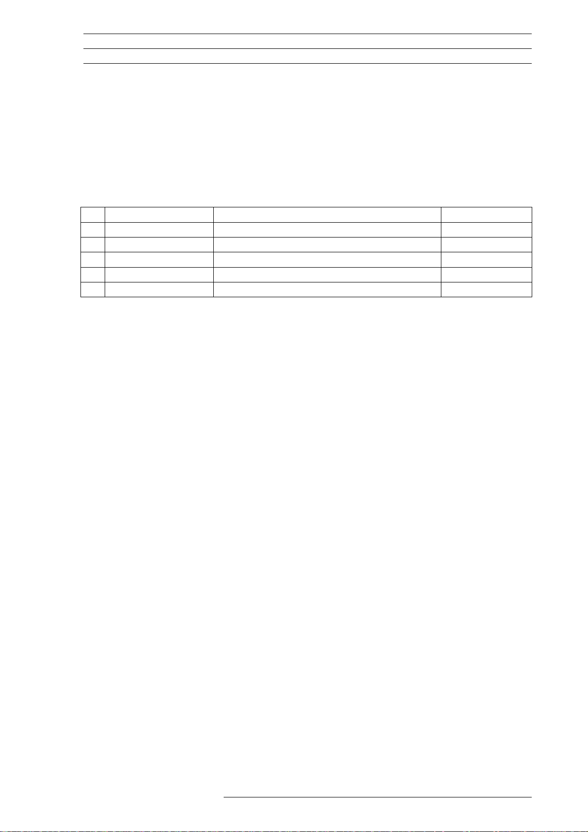
2.3 LIST OF DOCUMENTS
Subject Document Doc. No.
[1]
Installation
[2]
Networks
[3]
Windows CE
(this list of documents is not final)
Installation instructions General wiring instructions AWB2776-1569
Networks in brief AWB2776-1568
PANEL with WindowsCE AWB2776-1553
01/05 AWB2776-1559GB
© by Moeller GmbH
7
Page 10
Device Description Embedded HMI XVH-3x0 Hardware
Device Versions
3 DEVICE VERSIONS
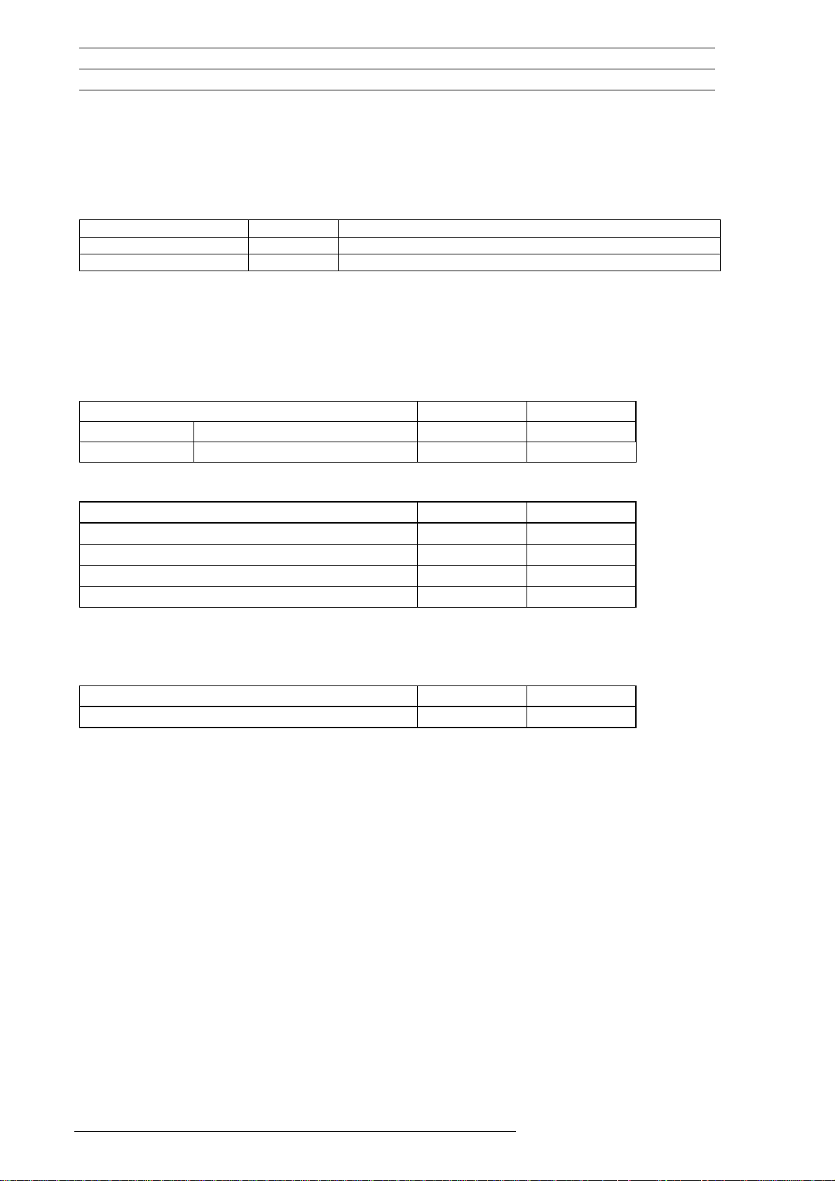
The XVH-330/340-57 Systems are available in the following versions:
Type Touch Front / Type of fixing
XVH-330-57XXX-x-13-x Resistive Standard / Fixing brackets
XVH-340-57XXX-x-13-x Infra-red Standard / Fixing brackets
3.1 SCOPE OF DELIVERY
Each device version is supplied with the following accessories:
Device version: XVH-330-57 XVH-340-57
-x-13-x
• •
• •
• •
• •
•
-x-13-x
Resistive touch Standard front
IR touch Standard front
Accessories (included)
4 fixing brackets for mounting the device
Sealing strip(for IP65)
Power supply plug connector
CompactFlash cover for the CompactFlash slot
Resistive touch pen
3.2 OPTIONS
OS Flash
Additional fixing brackets for IP65
• •
• •
8
01/05 AWB2776-1559GB
© by Moeller GmbH
Page 11
Hardware Device Description Embedded HMI XVH-3x0
Commissioning
4 COMMISSIONING
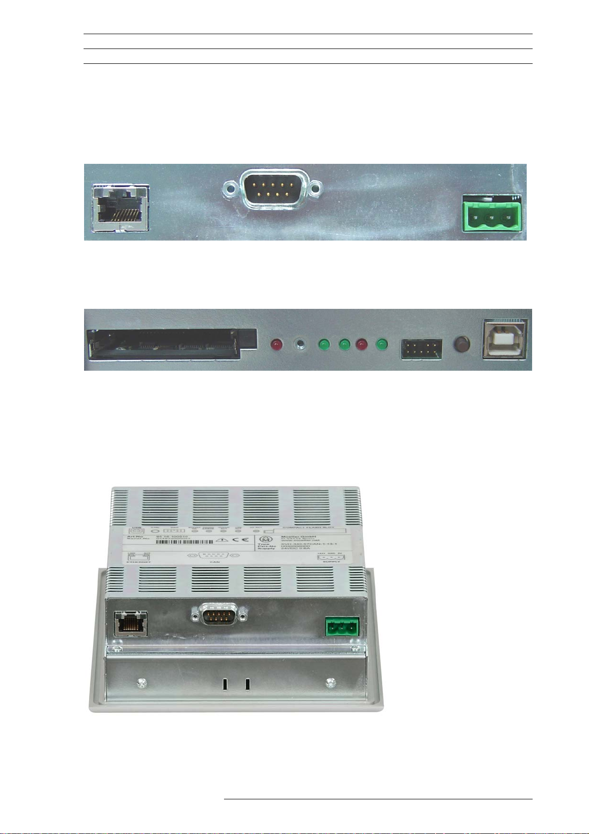
4.1 OVERVIEW OF THE TERMINALS
Ethernet
ComModule plug
(e.g. CAN)
Supply
USB Device
ÎLED functions see chap. 9.
The Ethernet, ComModule (e.g. CAN) and Supply terminals are located on the right of the device
when viewed from the rear. The terminal for the USB interface is located on the left of the device.
01/05 AWB2776-1559GB
© by Moeller GmbH
9
Page 12
Device Description Embedded HMI XVH-3x0 Hardware
Commissioning
4.2 GENERAL NOTES ON CABLING
Cabling should be carried out with special care in order to ensure
interference-free operation.
The EMC values stated in the technical data can only be guaranteed if the
connections and cables are prepared according to the specifications stated.
The cabling must be laid separately from low-voltage cables or isolated with
double or reinforced insulation.
Î Further information: Installation instructions, General wiring instructions [1]
4.3 CONNECTION TO THE POWER SUPPLY
System supply 24 VDC SELV (safety extra low voltage)
Not isolated
Current consumption Î Chapter 15
Fuse / protection Internal fuse / protection against reverse polarity
Housing potential Connected to 0 V terminal
Terminal type Screw terminal (screwdriver No. 3), pluggable
Cross section min. 0.75 mm2 / max. 2.5 mm2 (lead or wire)
min. AWG24 / max. AWG12
Stripping length 7 mm
Î Further technical data: Chapter 15
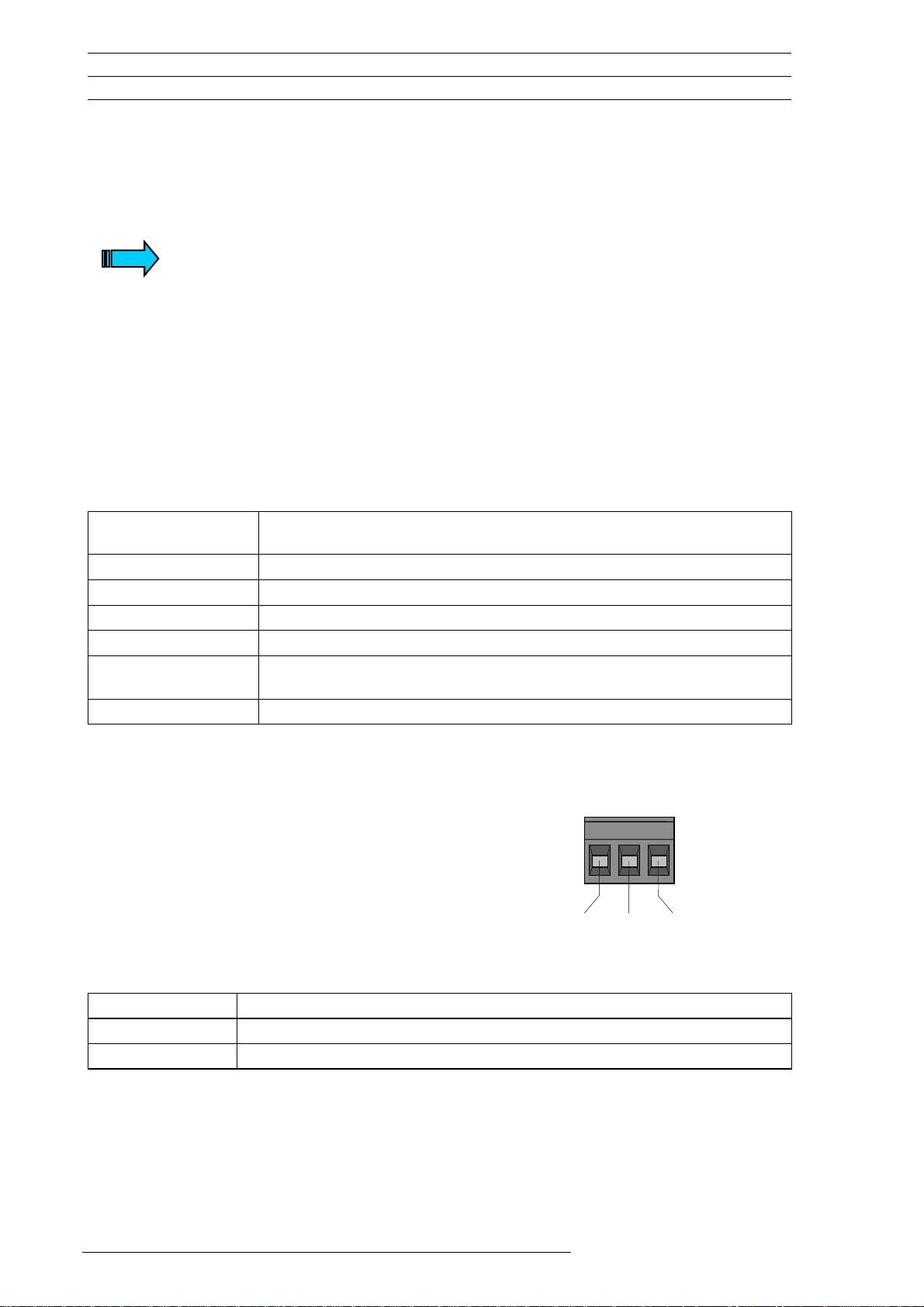
Plug connector: Phönix MSTB 2.5/3-ST-5.08
Phönix Order No. 1757022;
Supplied with unit
(view from the wiring side)
+24 VDC +24 VDC power supply
GND Functional ground, connected with housing (connection not compulsory)
0 V 0 V power supply (connected with housing)
+24 VDC GND 0 V
10
01/05 AWB2776-1559GB
© by Moeller GmbH
Page 13

Hardware Device Description Embedded HMI XVH-3x0
Commissioning
4.4 ETHERNET
RJ45 10/100 Mbit
Î LED functions: Chapter 9
Cabling
The network is implemented with shielded twisted pair cables (STP or UTP) and shielded RJ45 plug
connectors. The maximum permissible cable length is 100 m. See also the specification as per
EIA/TIA 568 TSB-36. When preparing the cables it must be ensured that the cable shield is correctly
connected to the connector housing.
A crossover cable must be used for connecting one device with another. A 1:1 cable must be used
when using a hub in the connection.
Î Further information: Installation instructions, General wiring instructions [1]
The IP addresses can be obtained from your system or network administrator.
IP addresses must be uniquely defined in an Ethernet network.
Further information: Networks in brief [2]
Î
01/05 AWB2776-1559GB
© by Moeller GmbH
11
Page 14

Device Description Embedded HMI XVH-3x0 Hardware
Commissioning
4.5 USB DEVICE
The XVH-330/340-57 supports USB 1.1.
A USB device interface is provided
Cabling
Only use USB standard cables with a shield. When preparing the cables it must be ensured that the
cable shield is correctly connected to the connector housing. The maximum permissible cable length
is 5 m.
Î Further information: Installation instructions, General wiring instructions [1]
12
01/05 AWB2776-1559GB
© by Moeller GmbH
Page 15

Hardware Device Description Embedded HMI XVH-3x0
Commissioning
4.6 EXPANSION MODULE INTERFACES (COMMODULE) OPTIONAL
4.6.1 CAN
The CAN interface is isolated.
Connector assignment
1 - nc
6
7
8
9
9pole
DSUB male
Case Shield Cable shield (connected with housing)
Pin 3 and 6 (CAN_GND) are both connected internally with the CAN Ground. Pins 4, 5 and 8 must not
be connected. The CAN bus driver is fed internally.
Pin no. Signal Description
1
2
3
4
5
2 CAN-L Data signal Low
3 GND Signal Ground
4 - nc
5 - nc
6 GND 0 V power supply
7 CAN-H Data signal High
8 -
9 -
The CAN interface is isolated.
The max. baud rate is 1 Mbit/s.
The terminating resistor must be provided externally, e.g. in the connector, and is
not part of the device.
The CAN connector is not provided with a supply for third-party devices.
Î Further information: Installation instructions, General wiring instructions [1]
01/05 AWB2776-1559GB
© by Moeller GmbH
13
Page 16

Device Description Embedded HMI XVH-3x0 Hardware
Commissioning
4.6.2 MPI
The MPI interface is an isolated RS485 interface.
Connector assignment
1
1 - nc
6
2
3
4
5
Connector
DSub female 9 - nc
1) The 0V terminal must always be wired.
9pole
7
8
9
Pin no. Signal Description
2 - nc
3 LINE B Receive/Transmit Data B
4 REP CTL Repeater Control
5 0 V Reference potential for the terminating
6 5 V Power supply for the bus terminating
7 - nc
8 LINE A Receive/Transmit Data A
Case Shield Cable shield (connected with housing)
resistors and the potential equalisation
line 1)
resistors
The MPI interface is isolated.
The max. baud rate is 1 Mbit/s.
The terminating resistors must be provided externally, e.g. in the connector, and
are not part of the device.
The 5V must not
be used as a power supply for systems of other suppliers.
Î Further information: Installation instructions, General wiring instructions [1]
14
01/05 AWB2776-1559GB
© by Moeller GmbH
Page 17

Hardware Device Description Embedded HMI XVH-3x0
System Control Button (CTRL)
5 SYSTEM CONTROL BUTTON (CTRL)
The Control button (CTRL) is used to activate the system functions of the operating system.
Î Further information on the exact functions: PANEL with WindowsCE [3]
The Control button is located on the side of the CompactFlash slot and the Test LED. Ensure the
accessibility of the device when it is mounted. Viewed from the rear, the Control button is accessible
on the left.
Control button
01/05 AWB2776-1559GB
© by Moeller GmbH
15
Page 18

Device Description Embedded HMI XVH-3x0 Hardware
System settings
6 SYSTEM SETTINGS
This is where network, display, date/time settings etc. are entered.
These can be set via Start ⇨ Programs ⇨ Control Panel.
Î Further information: PANEL with WindowsCE [3]
16
01/05 AWB2776-1559GB
© by Moeller GmbH
Page 19

Hardware Device Description Embedded HMI XVH-3x0
CompactFlash Slot
7 COMPACTFLASH SLOT
The XVH-330/340-57 is provided with a slot for a Type I or II CompactFlash card in compliance with
CF Specification 1.4. These cards store the project data and the operating system required for running
the XHV.
The CompactFlash card is not
We recommend the use of the CompactFlash cards supplied by Moeller in
order to ensure interference-free operation.
Moeller cannot offer support and does not accept any liability for
consequential damage arising from the use of CompactFlash cards offered
by other suppliers.
Viewed from the rear, the CompactFlash slot is accessible on the left.
View without cover
Ejector button CF ACT
supplied with the Panel .
View with cover
The CompactFlash card must only be inserted / removed when the red CF ACT
LED is not
Removing the CompactFlash card when the CF ACT LED is lit (access to
CompactFlash card in progress) may lead to data being lost or destroyed.
The device should only be operated with the CompactFlash cover fitted. The
CompactFlash card may otherwise fall out during operation.
lit.
01/05 AWB2776-1559GB
© by Moeller GmbH
17
Page 20

Device Description Embedded HMI XVH-3x0 Hardware
Expansion and Configuration Options
8 EXPANSION AND CONFIGURATION OPTIONS
8.1 DEVICE INTERVENTIONS
The measures described in this section require the housing cover to be removed. When the device is
opened, parts are accessible that may carry dangerous voltages. Removing the housing cover and
interventions on the internal parts of the device must only be carried out after the power supply has
been switched off and the power supply connector has been removed. Interventions and modifications
to the device that are not described in this document will invalidate the warranty agreement.
The housing cover is fixed with Torx T10 screws. In order to remove the cover, this must be pushed a
few millimetres against the LEDs after undoing the screws (4 screws).
Interventions on the device must only be carried out after the power supply has
been switched off. During operation device components carry dangerous voltage.
Safety precautions concerning electrostatic discharge (ESD) must be observed
when making interventions on the device.
18
01/05 AWB2776-1559GB
© by Moeller GmbH
Page 21

Hardware Device Description Embedded HMI XVH-3x0
Function and Control LEDs
9 FUNCTION AND CONTROL LEDS
The XVH is provided with different LEDs for monitoring functions on the unit:
Supply SUPPLY OK
Touch Controller TOUCH ERROR and TOUCH ACT
ComModule CMM ACT
CompactFlash CF ACT
Ethernet ACT and LINK
5 4 3 2 1
CF ACT CMM
ACT
TOUCH
ACT
TOUCH
ERROR
SUPPLY
OK
Cutout of the XVH with a view of the Control LED with CF cover.
(accessible from the rear left)
Power supply
1 SUPPLY OK (green)
TOUCH (IR type)
2 TOUCH ERROR (red)
3 TOUCH ACT green)
CMM (ComModule)
4 CMM ACT (green)
CF card
5 CF ACT (red)
Lit Internal system voltage present
Lit
Dark
Lit
Flashing
Dark
Lit
Flashing
Lit briefly Bus active (data traffic)
Lit briefly (chap. 7) CF card access
During startup
When touch function ready
Error
Contamination
or wrong calibration
During startup
When touch function ready
On touch actuation
(cleaning IR touch frame, chap. 11.1)
(res.touch, chap.11.2)
ETHERNET
6 LINK (green)
7 ACT (yellow)
6
01/05 AWB2776-1559GB
© by Moeller GmbH
Lit Active network connected and detected
Flashing Ethernet active (data traffic)
7
19
Page 22

Device Description Embedded HMI XVH-3x0 Hardware
Function and Control LEDs
Cutout of the XVH with a view of the FlashCard and Control LED without the CompactFlash cover.
20
01/05 AWB2776-1559GB
© by Moeller GmbH
Page 23

Hardware Device Description Embedded HMI XVH-3x0
Mounting Instructions
10 MOUNTING INSTRUCTIONS
10.1 GENERAL MOUNTING INSTRUCTIONS
All devices are mounted from the front, i.e. in a control panel.
Standard front
The device is fixed from the rear with 4 fixing brackets (M4 threaded pin with type 2 hexagon). Four
additional fixing brackets are required for mounting to IP 65.
The devices can be run at a maximum ambient temperature of 50°C. This refers to the area directly
next to the lower cooling slots when the device is mounted vertically. A clearance of 3 cm must be
maintained at the cooling slots to ensure unobstructed air convection.
Hot components such as a heavily loaded transformer must have a clearance of at least 15 cm.
Avoid the exposure of the flat screen to direct sunlight. The sunlight (UV component) reduces the
lifespan of the LCD crystals.
The temperature inside the XVH can be scanned via the Control Panel.
Î Further information: PANEL with WindowsCE [3]
The cooling slots must always be free in order to ensure the proper cooling of the
system.
Avoid the exposure of the flat screen to direct sunlight.
Ensure that operating elements (Control button, CF card) and terminals are still
accessible when the device is mounted.
The front panel should not exceed a maximum thickness of 5 mm, due to the
clamping range of the fixing brackets.
01/05 AWB2776-1559GB
© by Moeller GmbH
21
Page 24

Device Description Embedded HMI XVH-3x0 Hardware
Mounting Instructions
10.2 STANDARD FRONT
1. Insert the supplied sealing strip in the cut out groove of the front plate. Cut the tape to a suitable
length so that the joint is tight.
2. Push the device from the front into the cutout of the front panel.
3. Fix the device at two corners on the top and the bottom with the 4 fixing brackets supplied.
4. Additional fixing brackets are required for mounting to IP 65 (optional) or in the Ex Zone 22. These
brackets are positioned in the middle of each side.
22
01/05 AWB2776-1559GB
© by Moeller GmbH
Page 25

Hardware Device Description Embedded HMI XVH-3x0
Mounting Instructions
10.3 MECHANICAL DIMENSIONS
Einbautiefe
156
55
196
185
140
212
Standard front Resistive touch
01/05 AWB2776-1559GB
© by Moeller GmbH
23
Page 26

Device Description Embedded HMI XVH-3x0 Hardware
Mounting Instructions
10.4 FRONT PANEL CUTOUT STANDARD FRONT
Front panel cutout: 198.0 +1/-0 mm x 142.0 +1/-0 mm
142.0 +1/-0
198.0 +1/-0
The front panel should not exceed a maximum thickness of 5 mm, due to the
clamping range of the fixing brackets.
24
01/05 AWB2776-1559GB
© by Moeller GmbH
Page 27

Hardware Device Description Embedded HMI XVH-3x0
Notes on the Touch Screen
11 NOTES ON THE TOUCH SCREEN
11.1 INFRA-RED TOUCH
Basic touch screen function
The touch screen operates using an active light matrix in the infra-red range. The optical elements of
the light matrix are located behind the IR transparent plastic frame in the front panel of the device.
They are located in such a way that their radiation extends slightly out of the front pane. Each emitter
is assigned a receiver that is located on the other side. A touch on the screen is detected by the
simultaneous interruption of one or several channels on the X or Y axis.
Repeated touch actuations and those that cover an area greater than 20 mm x 20 mm are not
evaluated by the touch controller. Continuously interrupted channels caused by severe contamination
and dirt, or by the failure of an optical element are detected by the touch controller and are no longer
included in the evaluation.
Function test
A function test of the touch screen is permanently active. This test measures the signal levels of all IR
channels and compares them with initial signal values. The initial values are determined before the
device is delivered and stored in a retentive memory.
If the signal of one or several channels is below a minimum level relative to the initial values, this will
be indicated by an error message on the screen and the
signal level of this kind is normally due to severe contamination of the IR transparent plastic frame
which consequently has to be cleaned. The touch screen, however, remains fully functional.
Only a further increase in the contamination of the screen will lead to the continuous interruption of
one or several IR channels. IR channels that are continuously interrupted will be detected by the touch
controller and no longer included in the evaluation. In extreme cases, this may mean that individual
zones cannot be touch activated.
TOUCH ERROR LED (flashing). A reduced
Cleaning the Touch Screen
For proper operation ensure that the signal levels of the channels are not so severely reduced or
interrupted due to excessive contamination through dirt.
Clean the inside of the plastic frame on the device front regularly with a damp soft cloth. Ensure that
the surface is not scratched or scoured, especially when removing hard deposits and abrasive dust.
Do not expose the front of the device to solvents which may corrode and destroy the plastic frame and
foil (frame material: polycarbonate (PC); Foil material: polyester (PET); Display pane: non-reflective
glass; Carrier plate: aluminum).
01/05 AWB2776-1559GB
© by Moeller GmbH
25
Page 28

Device Description Embedded HMI XVH-3x0 Hardware
Notes on the Touch Screen
11.2 RESISTIVE TOUCH
Basic touch screen function
Resistive touch panels are based on two resistive foils or glass panels that are kept apart by means of
small spacers. The foils are contacted at the edges and thus connected to the evaluation circuit. A
slight touch pressure causes an electrical contact. Due to the voltage divider principle, a specific
current or resistance value is generated according to where the touch actuation occurred. A controller
evaluates these changes on touch contact and thus determines the touch position.
Actuation
The resistive touch panel must only be actuated with a special pen (supplied with the accessories) or
with a finger. When wearing gloves, these must be clean and must not be covered with abrasive dust
or sharp particles. The touch panel must not be operated with pointed objects or any writing
equipment (pens, pencil etc.).
Calibration
The resistive touch panel has to be calibrated on initial startup. In a dialog, the marked position must
be touched with the supplied pen
This calibration is carried out via the Control Panel.
Î Further information: PANEL with WindowsCE [3]
. The touch panel can be recalibrated as required.
Function test
Not yet specified
Cleaning the Touch Screen
Only clean the touch foil with a non
-abrasive cleaning material. Do not expose the front of the device
to solvents which may corrode and destroy the foil (foil material: polyester (PET); Carrier plate:
aluminum).
The touch panel must only be actuated with a special pen or with a finger.
26
01/05 AWB2776-1559GB
© by Moeller GmbH
Page 29

Hardware Device Description Embedded HMI XVH-3x0
Display Technology, Backlight
12 DISPLAY TECHNOLOGY, BACKLIGHT
An STN color LCD (passive) is used for the display. The image is produced by means of a backlight
that varies in color and intensity on account of the individual LCD cells (pixels).
The light of the backlight is produced by means of cold cathode tubes. The lifespan of the tubes is
limited, and depends on the actual operating conditions. The intensity of the brightness and the
number of start cycles are major factors in determining the lifespan of the tubes. Reducing the
brightness can considerably increase the lifespan of the device. Frequent switching, particularly at low
temperatures, will reduce the lifespan of the unit.
Therefore avoid the frequent switching on and off of the backlight or the entire system. Minimising the
brightness required is more effective than reducing the frequent on/off switching.
Î Further information: PANEL with WindowsCE [3]
.
01/05 AWB2776-1559GB
© by Moeller GmbH
27
Page 30

Device Description Embedded HMI XVH-3x0 Hardware
Maintenance and Repair
13 MAINTENANCE AND REPAIR
Cleaning the screen
Regular cleaning of the plastic frame of the device front is recommended to ensure trouble-free
operation of the IR touch screen. (Î Chap. 11.1)
Repairs
Repairs should only be carried out by the manufacturer or authorized repair centres. In this case,
please contact your local PANEL dealer or the Technical Support at
Moeller.(www.moeller.net/Support)
The warranty is not applicable if any modifications are made to the device that are not described in
this document.
Transport
Only the original packaging must be used for transporting the device.
28
01/05 AWB2776-1559GB
© by Moeller GmbH
Page 31

Hardware Device Description Embedded HMI XVH-3x0
Disposal
14 DISPOSAL
Devices that are no longer used, must be properly disposed of or returned to the manufacturer or
sales for their proper disposal.
Special note:
• The device contains a soldered lithium battery.
• The LCD unit is fitted with a fluorescent tube for the backlight. This contains mercury.
Materials Device
Housing: Galvanized sheet steel
Front plate: Aluminum, Peraluman 101 anodized
IR frame: Polycarbonate (PC);
Front glass: Non-reflective glass
Foil: Autotype polyester (PET);
Materials Packaging
Boxes: Cardboard
Transport protection: TFL foam (polyethylene)
Plastic bag: Polyethylene
01/05 AWB2776-1559GB
© by Moeller GmbH
29
Page 32

Device Description Embedded HMI XVH-3x0 Hardware
Technical Data
15 TECHNICAL DATA
Display
Resolution 320 x 240 pixels(1/4 VGA)
Number of colors 256 colors
Display area 115 mm x 86 mm
Backlight 1xCCFL dimmable via softwarer
Contrast ratio Normally 35
Brightness normally 150cd/m2
Lifespan of backlight min. 25'000 h / normally. 50'000h
Front plate IR: Glass, non-reflective, scratchproof
Operation
Resolution 47x 31 log.
Type Resistive-touch
Resolution 4-wire
Ethernet
USB Device
Connection Type B (4pole)
CAN (optional)
MPI (optional)
Connection Sub-D 9-pole male
CompactFlash Slot
Technology ATA 3.3V
NVSRAM
Flash
Power supply
Voltage range 24 VDC to DIN 19240
Voltage dips 20ms from rated voltage (24V)
Protection agains reverse
Fuse protection Yes (internal fuse)
Potential isolation No
Power consumption max. 14W / 24VDC
Technology 5,7” STN color LCD
Res: Polyester-foil
Type Infra-red touch
Type Fast Ethernet 100Base-TX IEEE 802.3u
(100 MBit/s)
Ethernet 10Base-T IEEE 802.3 (10 MBit/s)
Connection RJ45 female
Type 1 x USB 1.1 not isolated
Type CAN, isolated
Connection CiA, Sub-D 9-pole male
Type MPI, isolated
Type CompactFlash Card Type I/II
(CompactFlash Spec. 1.4)
Type 32 Kbyte (without battery)
Type 1.5 Mbyte
Rated voltage 24 VDC SELV, safety extra low voltage
20.4...28.8 VDC absolute value with ripple
19.2...30.0 VDC 35.0 VDC for a duration of
< 100ms
2ms from undervoltage (19.2V)
Yes
polarity
The 0V- connection is directly connected to
the housing potential (GND)
Inrush max. 2.5A2s
30
01/05 AWB2776-1559GB
© by Moeller GmbH
Page 33

Hardware Device Description Embedded HMI XVH-3x0
Real-time clock
Battery type CR2032 (190mA/h) maintenance-free
(battery backup) Data retention >10 years (in de-energized state)
Weight
Approx. 1,6 kg
Dimensions
W x H x D 212 x 156 x 79 mm (mounting depth 55mm)
Cutout 198 x 142 mm (+1/-0mm)
Degree of protection
Front IP 65 (to EN 60529)
(nur mit mitgelieferter Dichtung und 8
Halteklammern)
Ambient conditions
Operating climate 0...50°C, 10...95% rel. Air humidity, non-
condensing
Storage climate -20...60°C, 10...95% rel. Air humidity, non-
condensing
Vibration / Shock / Fall test Vibration: IEC68-2-6
Shock: IEC68-2-27
Fall test: IEC68-2-32
EMC (CE)
EN 61000-6-2, EN 61000-6-4
EN 61000-6-3
EN 61131-2
Safetyt
EN60950
UL60950 (UL)
Explosion protection
(CE)
All standard devices Zone 22, Category 3D
Product standards
EN 50178, Electrical equipment for use in
electrical installations
Technical Data
01/05 AWB2776-1559GB
© by Moeller GmbH
31
Page 34

Device Description Embedded HMI XVH-3x0 Hardware
EU Conformity/Safety
16 EU CONFORMITY/SAFETY
16.1 EMC
The XVH meets the requirements specified by the EC Council Directives for harmonizing the
regulations of EC member states relating to electromagnetic compatibility (89/336/EEC).
16.2 EXPLOSION PROTECTION
16.2.1 ZONE 22, CATEGORY 3D
The XVH-330-340-5.7 Systems meet the requirements specified by the EC Council Directives for
harmonizing the regulations of EC member states for the proper use of devices and protective
systems in hazardous areas (94/9/EEC) for Zone 22, Category 3D.
Information on the nameplate
II 3D X
T 70°C
EEx II
IP5x
Applicable standards:
EN 50014 Electrical apparatus for potentially explosive atmospheres
EN 60079-0 Electrical apparatus for explosive gas atmospheres. General requirements
EN 50281-1-1 Electrical apparatus for use in the presence of combustible dust
Part 1-1: Electrical apparatus with protection by enclosures – design and testing
EN 13463-1 Non-electrical equipment for potentially explosive atmospheres
The X on the nameplate stands for:
Must not be subjected to dangerous blows and nor erected in the tracks of
cranes.
In order to achieve protection compliant with IP5x, installation must be carried
out with the supplied seal and the optional retaining bracket kit for IP65. (see
also Chap. Fehler! Verweisquelle konnte nicht gefunden werden.)
Ambient temperature range 0°C ≤Ta ≤ +50°C
32
01/05 AWB2776-1559GB
© by Moeller GmbH
Page 35

Hardware Device Description Embedded HMI XVH-3x0
Safety / North American Approvals
17 SAFETY / NORTH AMERICAN APPROVALS
The standards EN60950-1 and UL60950 were used for the assessment of electrical safety.
The XVH-330/340-57 Systems are approved for the USA and Canada.
UL60950 (UL File No. E208621)
01/05 AWB2776-1559GB
© by Moeller GmbH
33
Page 36

Device Description Embedded HMI XVH-3x0 Hardware
Safety / North American Approvals
34
01/05 AWB2776-1559GB
© by Moeller GmbH
Page 37

Hardware Device Description Embedded HMI XVH-3x0
01/05 AWB2776-1559GB
© by Moeller GmbH
35
Page 38

Device Description Embedded HMI XVH-3x0 Hardware
Moeller GmbH
Industrial Automation
Hein-Moeller-Str. 7-11
D-53115 Bonn
Tel : +49 (0) 228-602-0
Fax : +49 (0) 228-602-2275
E-Mail : info@moeller.net
Internet : http://www.moeller.net
36
01/05 AWB2776-1559GB
© by Moeller GmbH
 Loading...