

Page 1

SmartWire Startup Guide V1.02
SmartWire Startup Guide V1.02
© by Moeller GmbH 1 / 42
Page 2

SmartWire Startup Guide V1.02
The document can be found under the following path:
ftp://ftp.moeller.net/SMARTWIRE/ENGLISH/01_PRODUCT/08_STARTUP_GUIDE
{ DOWNLOAD }
All rights, including those of translation, reserved. No part of this manual may be
reproduced, stored in a retrieval system, or transmitted in any form or by any means,
electronic, mechanical, photocopying, micro-filming, recording or otherwise, without
the prior written permission of Moeller GmbH, Bonn.
Changes:
V1.0 Æ V1.01 Moeller logo updated
V1.01 Æ V1.02 Screenshots updated
© by Moeller GmbH 2 / 42
Page 3

SmartWire Startup Guide V1.02
Contents
1 Introduction...................................................................................................... 4
2 System components for motor starters with SmartWire.............................. 5
3 Connections on the motor starter .................................................................. 7
4 Assembling a motor starter row..................................................................... 8
5 Electrically commissioning SmartWire........................................................ 10
6 SmartWire integration for XC100/200 via Profibus DP................................ 12
6.1 PLC connection.............................................................................................................12
6.2 Installing the GSD file ...................................................................................................13
6.3 Creating a program in easySoft CoDeSys....................................................................14
6.4 Setting for Profibus node monitoring.............................................................................21
6.5 Diagnostics ...................................................................................................................22
6.5.1 XC100/200 system diagnostics................................................................................................... 22
6.5.2 Profibus DP diagnostics.............................................................................................................. 24
6.6 Example program for XC200 (SWIRE-XC200-ProfibusDP.pro)....................................27
7 SmartWire integration for XC100/200 via CANopen.................................... 28
7.1 PLC connection.............................................................................................................28
7.2 Installing the EDS file....................................................................................................29
7.3 Creating a program in easySoft CoDeSys....................................................................29
7.4 Settings for CANopen node monitoring with Node guarding.........................................33
7.5 Settings for the CANopen Heartbeat node monitoring..................................................34
7.6 CANopen slave monitoring ...........................................................................................35
7.7 Example program for XC200 (SWIRE-XC200-CANopen.pro)......................................39
8 SmartWire integration for easy800 via easyNET......................................... 40
9 SmartWire integration for ECP4 via CANopen ............................................ 40
10 SmartWire integration for S7-300 via Profibus DP...................................... 40
© by Moeller GmbH 3 / 42
Page 4
SmartWire Startup Guide V1.02
1 Introduction
SmartWire enables switching devices to be connected to a PLC without the need for
any complex control circuit wiring. The control wiring between the PLC and the
switchgear is replaced by the plug-in SmartWire module and pre-assembled
connection cables. The wiring requirement is drastically reduced and thus makes
wiring errors a thing of the past. This saves time and money during mounting,
commissioning and troubleshooting during operation.
SmartWire is an addition to the well-established range of Moeller switchgear and is
designed to be an accessory for standard devices. The flexibility of the switchgear is
fully retained since all known system accessories can still be used. The use of
standard devices reduces the stock-keeping costs required and ensures the
worldwide availability of replacement parts.
© by Moeller GmbH 4 / 42
Page 5
SmartWire Startup Guide V1.02
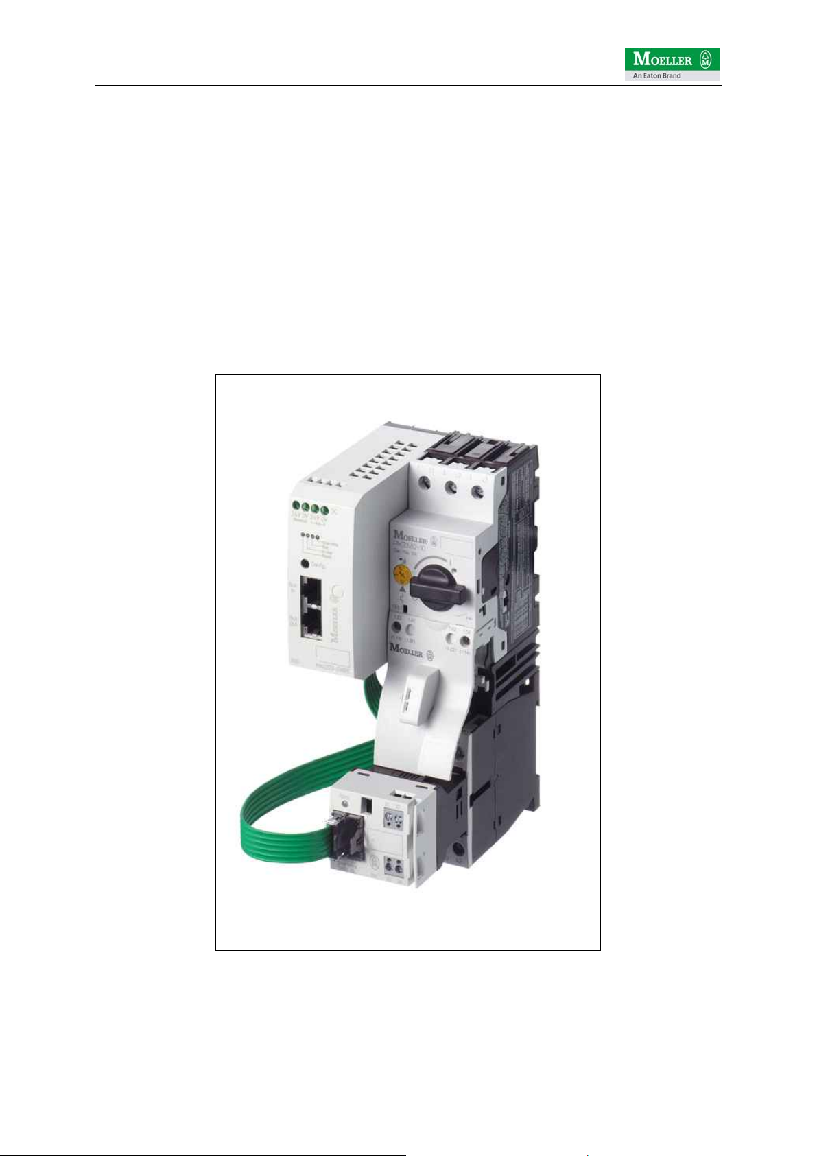
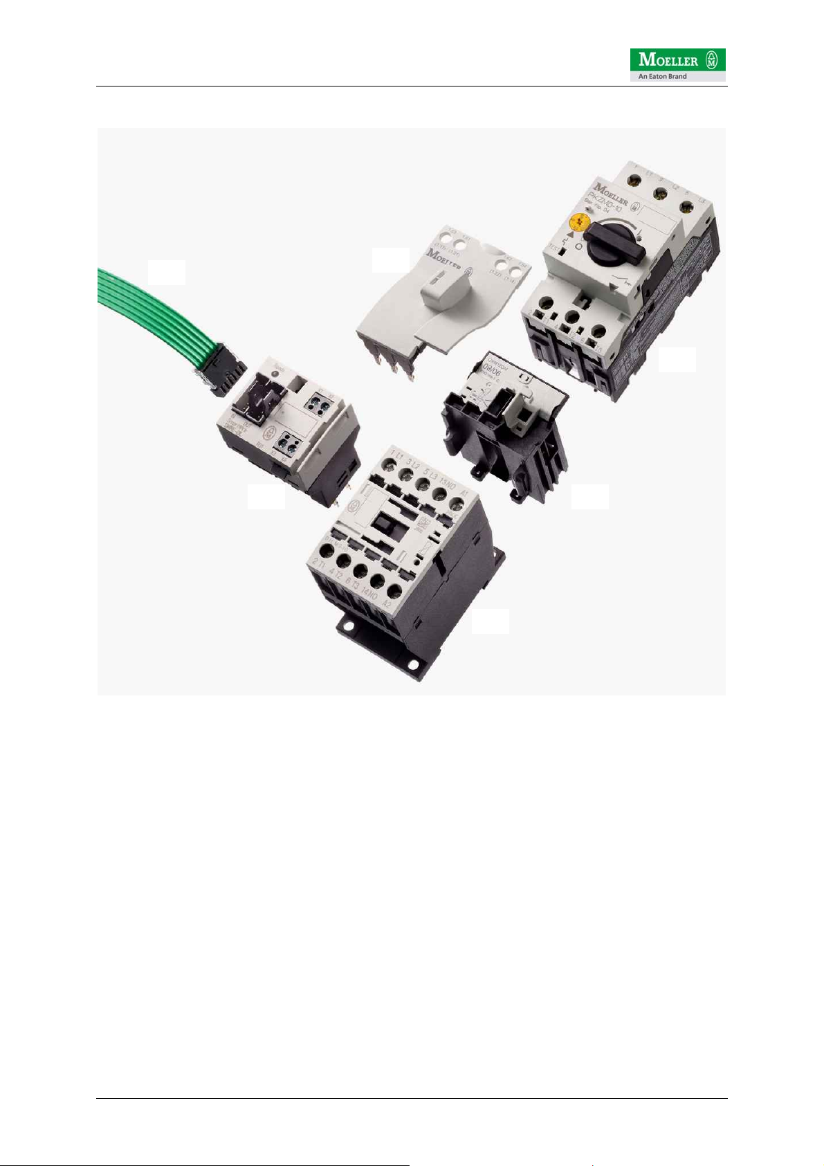
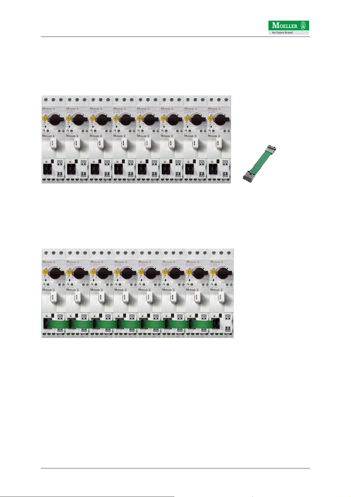
2 System components for motor starters with SmartWire
(6)
(4)
(1)
(5) (2)
(3)
The following pages describe the setup, configuration and function of the SmartWire
system using eight Moeller motor starters with the "SWIRE-DIL" SmartWire module
for DILM contactors.
The motor starters presented here consist of 5 components:
1) PKZM motor-protective circuit-breaker
2) Connection element
3) DILM contactor
4) Tool-less plug connector
5) SmartWire module for DILM "SWIRE-DIL"
6) SmartWire connection cable "SWIRE-CAB-xxx"
© by Moeller GmbH 5 / 42
Page 6
SmartWire Startup Guide V1.02
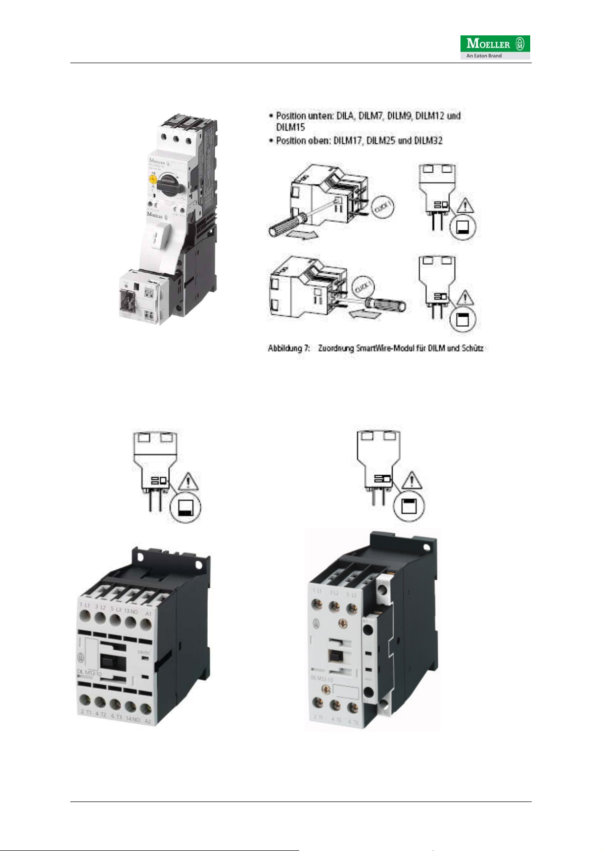
A motor starter is assembled simply from these 5 components.
Before fitting the SWIRE-DIL to the corresponding contactor, it must be ensured that
the position of the terminal pin is set correctly.
DILM contactor size 1 DILM contactor size 2
© by Moeller GmbH 6 / 42
Page 7
SmartWire Startup Guide V1.02
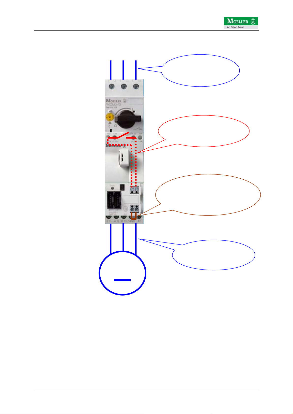
3 Connections on the motor starter
L1 L2 L3
Incomer wiring
(AC load circuit)
X1/X2 optional wiring
NHI (auxiliary contact
for PKZM)
X3/X4 for opening
the contactor control circuit
(Jumpered as standard)
The SWIRE-DIL has 4 screw terminals, X1/X2 and X3/X4.
X1/X2 is provided with a digital input for isolated contacts. This input is designed for
connecting the NHI auxiliary contact of the PKZ and thus indicates the status of the
PKZ (off/tripped and on) to the SWIRE-DIL.
A jumper (fitted as standard) at X3/X4 closes the control circuit for the contactor.
Opening the connection at X3/X4 makes it possible to interrupt the circuit for the
contactor (independently of the SWIRE-DIL control logic). X3/X4 enables, for
example, the electrical interlock of the contactor for a reversing starter combination.
M
Wiring for motor
feeder
(AC load circuit)
© by Moeller GmbH 7 / 42
Page 8
SmartWire Startup Guide V1.02
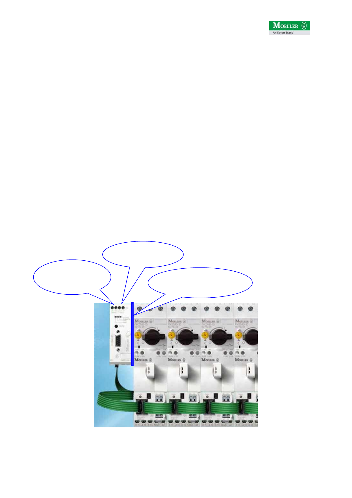
4 Assembling a motor starter row
The assembly of the system couldn't be easier. The motor starters are firstly fitted in
succession onto the mounting rail. The NHI may have been installed on the PKZ
beforehand and the connection cables connected to the terminal X1/X2.
All SWIRE-DILs are then interconnected using the SmartWire connection cables. The
SWIRE-CAB-008 is recommended for connecting two starters with (DILM7…11
contactors). If adjacent contactors are not identical, e.g. DILM9 next to DILM15 or
vice versa, the next larger connection cable SWIRE-CAB-011 is recommended.
© by Moeller GmbH 8 / 42
Page 9
SmartWire Startup Guide V1.02
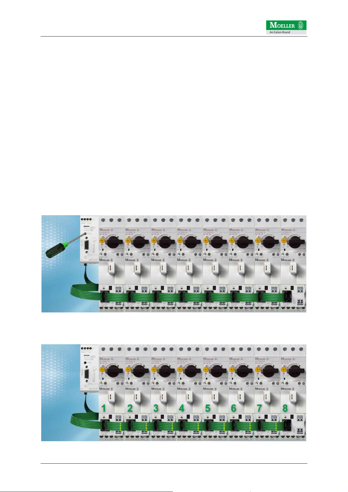
The next step involves the installation of the fieldbus gateway. The following
interfaces are possible at present:
1) SWIRE-GW-DP Æ for connecting to Profibus DP V0
2) easy223-SWIRE Æ CANopen mode: for connecting to a CANopen master
3) easy223-SWIRE Æ easyNET mode: for connecting to an easyNET for easy800
Ideally, the fieldbus gateway is positioned approx. 10 mm away from the first starter.
SWIRE-CAB-015 is recommended as the SmartWire cable.
The gateway requires two operating voltages:
a) U
b) U
Interface
Aux
: used for supplying the gateway and the SmartWire modules.
: supply voltage here for the contactors on the motor starter
ATTENTION!
The power supply must be provided with appropriate fuse protection.
a) U
b) U
Interface
Aux
: 1A fuse
: 3A fuse
Further information on this is provided in the technical descriptions (AWBs) of the
SmartWire components.
24VDC power
supply
for SWIRE devices
24VDC incomer
for DILM contactors
Distance from gateway to
the first starter, ideally
approx. 10mm
© by Moeller GmbH 9 / 42
Page 10
SmartWire Startup Guide V1.02
5 Electrically commissioning SmartWire
The SmartWire system which is connected to the higher-level PLC via the fieldbus
gateway in place can be configured independently of the controlling PLC and
commissioned.
After the power supply is switched on, the SmartWire gateway always checks the
connected SmartWire modules and compares this with the internally stored
configuration. The SmartWire gateway is factory set without a reference
configuration. In other words, it does not expect to find any modules.
In this example with 8 motor starters and thus also SmartWire modules, the
SmartWire gateway will detect the deviation when the first module is checked. This is
indicated by the regular flashing of the SmartWire LED on the gateway and on the
first SWIRE-DIL. The LEDs of SWIRE-DILs 2-7 flash in pulses.
This means that they are in operation but have not yet been accessed by the
gateway, since the first module does not match the reference configuration in the
SmartWire gateway.
The currently connected configuration can be transferred by pressing the
configuration button on the gateway. This must be held down > 1 second. If this time
is exceeded, the Ready LED will change from slow to fast flashing and will thus
indicate that the configuration process has been initiated. The configuration button
can then be released.
The gateway then carries out an automatic configuration so that all stations are
addressed in turn (in this case 1-8).
© by Moeller GmbH 10 / 42
Page 11

SmartWire Startup Guide V1.02
Once this configuration of the gateway has been completed successfully, this is
indicated by the permanently lit SWIRE-LED on the gateway and all permanently lit
Ready LEDs on the SmartWire modules (apart from the SWIRE-DILs). This means
that the actual configuration has been accepted by the gateway and stored internally.
The complete SmartWire system is now fully operational.
Note: during the configuration, the SmartWire gateway addresses the connected
stations in turn. With a maximum configuration the modules are numbered from 1-16.
The only other steps required apply to the fieldbus system and its configuration, as
well as the programming in the higher-level PLC.
The following chapters describe the integration of the SmartWire system consisting of
SmartWire gateway and SmartWire modules.
The previously described configuration of 8 motor starters with the 8 SWIRE-DIL
modules is used as an example.
© by Moeller GmbH 11 / 42
Page 12
SmartWire Startup Guide V1.02
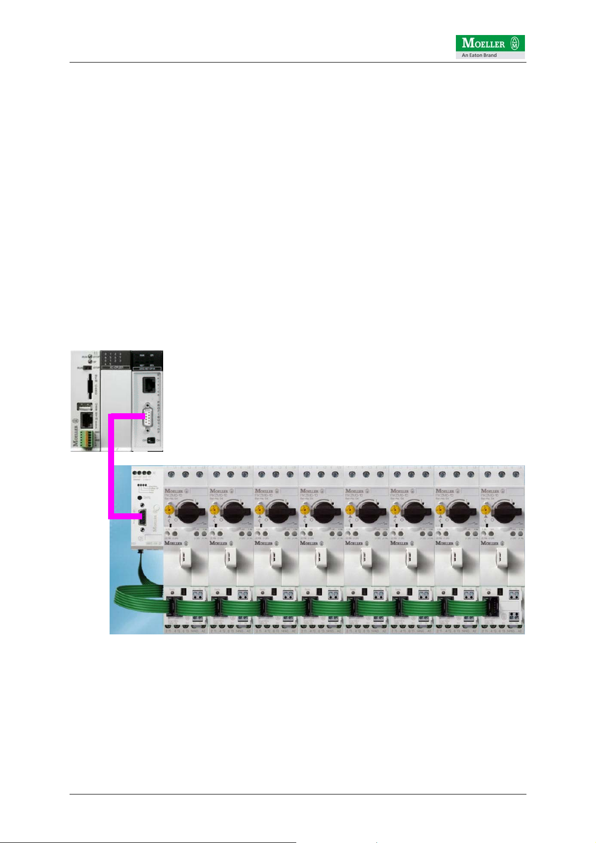
6 SmartWire integration for XC100/200 via Profibus DP
This section assumes the following example PLC configuration:
• Moeller XC-CPU201-256K-8DI-6DO
• Moeller XIOC-NET-DP-M (Profibus master module for Moeller XC100/200)
easySoft CoDeSys V2.3.5.8 (Build Dec 7 2005) is used for programming. The current
service pack ECP_Update01_07.exe should also be installed. The service pack can
be downloaded from the Moeller ftp server at the following address:
ftp://ftp.moeller.net/AUTOMATION/DOWNLOAD/SOFTWARE_UPDATES/EASYSOF
T_CODESYS/V2.3.5/
6.1 PLC connection
The Profibus DP master module is connected via a standard Profibus fieldbus cable
to the SWIRE-GW-DP SmartWire gateway. It must be ensured that the bus ends of
the Profibus DP connection cable are correctly terminated.
© by Moeller GmbH 12 / 42
Page 13
SmartWire Startup Guide V1.02
6.2 Installing the GSD file
The configuration of the master and slave devices in easySoft CoDeSys is based on
the GSD files. These device data files are supplied by the manufacturer and contain
a standard description of the characteristic properties of a PROFIBUS DP device.
Ensure that the required GSD files are already located in the specified directory for
the configuration files before CoDeSys is started.
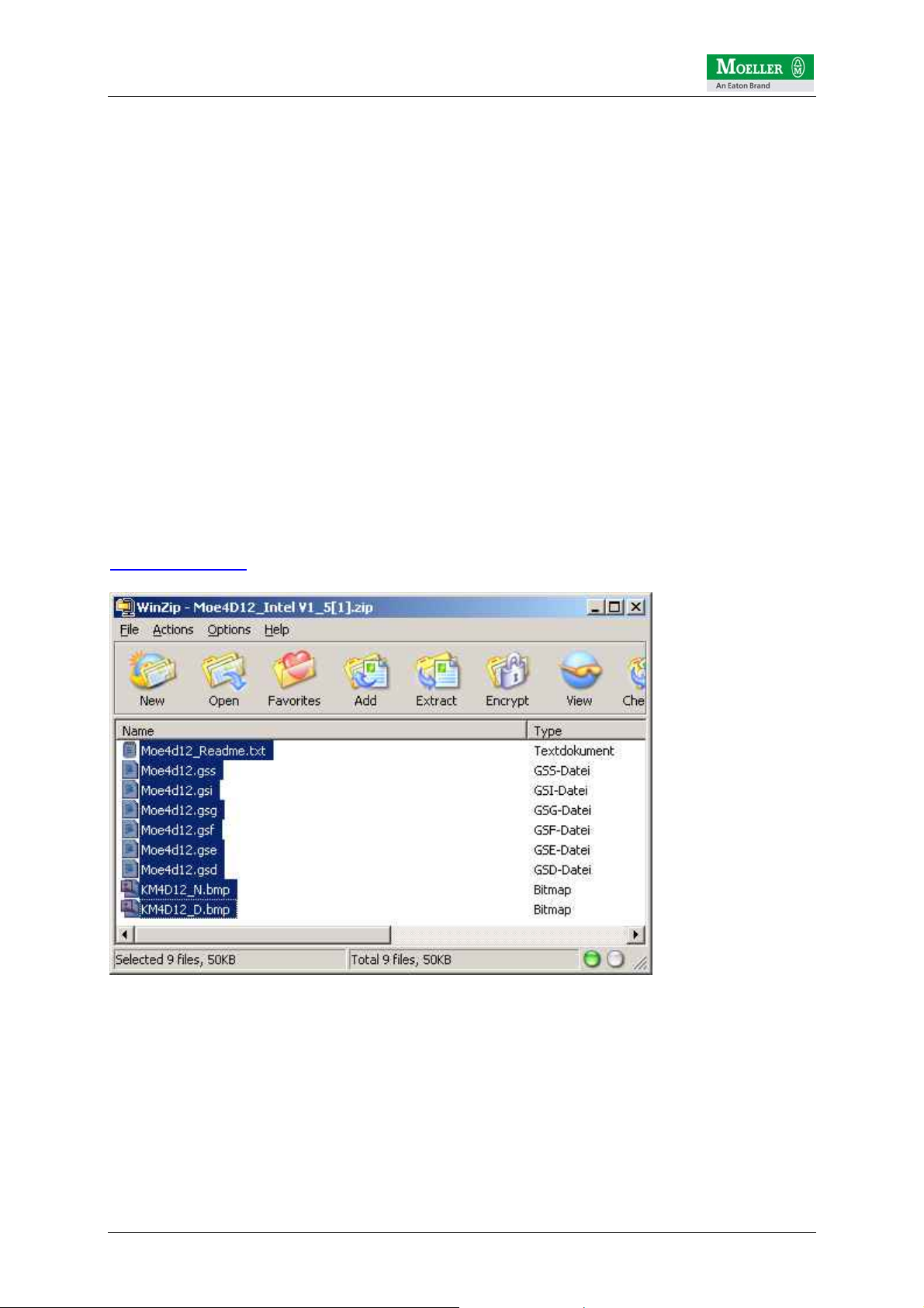
The following GSD files are required for the SmartWire Profibus DP gateway.
Moe4D12_Intel V1_5.zip
PROFIBUS-DP device data file (GSD) for SWIRE-GW-DP DPV0 slave
GSD files for PLCs operating with the Intel data format.
(e.g. Moeller PS4, XC100, XC200...)
They can be downloaded from the Moeller ftp server at the following path:
ftp://ftp.moeller.net/AUTOMATION/DOWNLOAD/
CONFIGURATIONFILES_CFG_GSD_EDS/SEVERAL_PARTS/
PROFIBUS/SMARTWIRE/
{ DOWNLOAD }
Copy all the files in the zip folder to the following easySoft CoDeSys folder:
C:\Programs\Moeller Software\easy Soft CoDeSys V2.3.5\easy Soft
CoDeSys\Library\PLCConf
© by Moeller GmbH 13 / 42
Page 14

SmartWire Startup Guide V1.02
6.3 Creating a program in easySoft CoDeSys
First start the easySoft CoDeSys software and create a new project (in this case for
XC200).
Then define the language for the MAIN program (in this case ST)
© by Moeller GmbH 14 / 42
Page 15

SmartWire Startup Guide V1.02
Then select the Resources tab and select PLC configuration
© by Moeller GmbH 15 / 42
Page 16

SmartWire Startup Guide V1.02
At the point with the first EMPTY SLOT add the Profibus DP master module (XIOCNET-DP-M):
© by Moeller GmbH 16 / 42
Page 17

SmartWire Startup Guide V1.02
The Profibus DP slave (in this case SWIRE-GW-DP) can then be added to the PLC
configuration.
The Profibus DP slave address must be added in the DP Parameters tab for the
XIOC-NET-DP-M module. In this case 3 is selected.
Version of the
GSD file
Node address of
the Profibus slave
SWIRE-GW-DP
The currently valid version of the GSD file for the SWIRE-GW-DP is V1.5
© by Moeller GmbH 17 / 42
Page 18

SmartWire Startup Guide V1.02
The setting of the Profibus node address is made via the DIP switches on the
SWIRE-GW-DP:
Setting of the
Profibus address via
DIP switches
The reference configuration on the SmartWire line is defined in the Inputs/Outputs
tab. This configuration is awaited by the Profibus DP master during the startup. If the
reference configuration of the SmartWire line set here does not match the actual
configuration, the SWIRE-GW-DP operation will not start up properly.
In this example a SmartWire line was set up with 8 motor starters and therefore also
8 SWIRE-DIL modules.
© by Moeller GmbH 18 / 42
Page 19

SmartWire Startup Guide V1.02
The reference configuration must therefore be set as follows:
Each SmartWire module has assigned to it a specific address area for status and
control data. A total of 2 bytes is reserved for the SWIRE-DIL module.
In this example one byte is reserved for the control data (%QB2) of the first SWIREDIL and one byte for the status data (%IB6). The other bytes are assigned in
ascending order accordingly for the other SWIRE-DIL modules.
The absolute addresses can be used directly in the PLC program.
The following assignment is used for the SWIRE-DIL:
Control data for SWIRE-DIL (%QX…)
bit Function
0 Contactor (on/off)
1 n.n.
2 n.n.
3 n.n.
4 ----5 ----6 ----7 -----
© by Moeller GmbH 19 / 42
Page 20

SmartWire Startup Guide V1.02
Status data for SWIRE-DIL (%IX…)
bit Function
0 Contactor switch position (on/off)
1 PKZ switch status (tripped/on)
2 n.n.
3 n.n.
4 n.n.
5 n.n.
6 n.n.
7 Slave status (0=ok, 1=internal error) *
* = Note: This bit must not be confused with the Profibus DP diagnostic data block. It
is cyclically transferred with the process data and indicates an internal device error.
In the event of a fault on the SmartWire module, this bit is not set in certain cases.
The basic function of the module on the SmartWire must therefore be monitored via
the Profibus diagnostics. This is described on the following pages.
Another SmartWire module is currently available. This is a digital I/O module with the
designation SWIRE-4DI-2DO-R. It has 4 digital inputs for potentially isolated contacts
and 2 digital relay outputs.
This module has the following control and status byte assignment:
Control data for SWIRE-4DI-2DO-R (%QX…)
bit Function
0 Digital output Q1
1 Digital output Q2
2 n.n.
3 n.n.
4 ----5 ----6 ----7 -----
Status data for SWIRE-4DI-2DO-R (%IX…)
bit Function
0 Digital input I1 (on/off)
1 Digital input I2 (on/off)
2 Digital input I3 (on/off)
3 Digital input I4 (on/off)
4 n.n.
5 n.n.
6 n.n.
7 Slave status (0=ok, 1=internal error)
© by Moeller GmbH 20 / 42
Page 21

SmartWire Startup Guide V1.02
6.4 Setting for Profibus node monitoring
Each Profibus node can monitor the communication from the Profibus master. If, for
example, in a running SmartWire system in which some contactors are controlled via
the SWIRE-DIL, Profibus is to be disconnected, this is detected in the SWIRE-GWDP by means of the watchdog functionality. The SWIRE-GW-DP then switches all
SWIRE-DIL modules so that the contactors drop out. For the SWIRE-GW-DP
SmartWire gateway the watchdog function should therefore be switched on. The
watchdog time should be selected according to the application. In this case 1000ms
was selected.
Activated watchdog
function
© by Moeller GmbH 21 / 42
Page 22

SmartWire Startup Guide V1.02
6.5 Diagnostics
In order to use the diagnostics function, the library xSysDiagLib.lib must be added to
the Library Manager beforehand.
Two function blocks are available for analyzing the diagnostic data:
• xDiag_SystemDiag
• xDiag_ModuleDiag
Software requirements:
• XC100: from V3.10
• XC200: from V1.03.02
6.5.1 XC100/200 system diagnostics The function block xDiag_SystemDiag can be used to monitor the XC100/200 PLC
system. The module diagnostics therefore refers to the entire XC100/200 system. In
this example, the XC200 is only fitted with another module, the XIOC-NET-DP-M. It is
installed at position 1 on the XIOC backplane. The positions 2 to n can be used as
required.
XC100 1 2 3 … n
In order to evaluate the system diagnostics in the PLC program, an instance of the
xDIAG_SystemDiag function block must be declared beforehand. ATTENTION! This
instance must be declared globally (i.e. in the global variables folder).
© by Moeller GmbH 22 / 42
Page 23

SmartWire Startup Guide V1.02
VAR_GLOBAL
XcSystemDiag : xDIAG_SystemDiag;
END_VAR
The following instructions cause the cyclical processing of the system diagnostics
and the monitoring of the Profibus master module XIOC-NET-DP-M on slot 1 of the
XC controller.
The diagnostics information is located in array element abyXcModuleInfo[1].
If the Profibus module is operating correctly, this byte contains the value 3. Otherwise
there is a problem with the module.
VAR
byXcModuleInfo : BYTE;
DIG_OUT_CPU_0 : BOOL;
END_VAR
Æ Further information on the system diagnostics function is provided in the
description "Function Blocks for easySoft CoDeSys 02/05 AWB2786-1456G.
© by Moeller GmbH 23 / 42
Page 24

SmartWire Startup Guide V1.02
6.5.2 Profibus DP diagnostics For Profibus diagnostics (in this case for monitoring the XIOC-NET-DP-M Profibus
master module described) the xDiag_ModuleDiag function block is used.
ATTENTION! The instance of the xDIAG_ModuleDiag FB must also be declared in
the "global variables" folder.
VAR_GLOBAL
XcSystemDiag : xDIAG_SystemDiag;
ProfibusDiag : xDIAG_ModuleDiag;
END_VAR
The following instructions cause the diagnostics for the XIOC-NET-DP-M Profibus
master module (slot = 1 of the XC PLC system) and the connected Profibus slave
SWIRE-GW-DP (Profibus slave address (Index) = 3) to be evaluated cyclically.
The result of the diagnostics evaluation via FB xDIAG_ModuleDiag is stored in the
array element abyExtendedInfo. If required, these can then be copied to user-defined
variables and further processed.
The following table provides information on the specific diagnostics data:
© by Moeller GmbH 24 / 42
Page 25

SmartWire Startup Guide V1.02
abyExtendedInfo Meaning
0 Profibus DP slave address
1..4 No meaning
5 Length bytes of the device diagnostics *
6, 7 No meaning
8 Byte 1 Profibus standard diagnostics (STATUS 1)
bit0: Device not responding
bit1: Slave not ready
bit2: Divergent configuration
bit3: Extended diagnostics data present
bit4: Unknown command
bit5: Invalid response
bit6: Incomplete parametric programming
bit7: Parameterization by another master
9 Byte 2 Profibus standard diagnostics (STATUS 2)
bit0: Ready for new startup sequence
bit1: No parameterization
bit2: 1
bit3: Watchdog activated
bit4: FREEZE command active
bit5: SYNC command active
bit6: Reserved
bit7: Slave not configured
10 Byte 3 Profibus standard diagnostics
Æ No meaning
11 Byte 4 Profibus standard diagnostics
Æ Profibus DP master address
12, 13 Byte 5,6 Profibus standard diagnostics
Æ Profibus DP slave ID number
Profibus DP standard diagnostics data block (=
6 bytes)
For SWIRE-GW-DP: 77
dec
/ 18
= 4D12
dec
hex
14 Length byte of device-specific data **
Æ for SWIRE-GW-DP with max. 16 SWIRE slaves = 8
15 Status type (130)
Æ for diagnostics message in HW configurator (PC)
16 Slot number (0)
Æ Diagnostics refers to SWIRE-GW-DP
17 Status specifier (0)
Æ No other information present
18 Status SmartWire module 1-4
bit0/1: SmartWire module 1
bit2/3: SmartWire module 2
bit4/5: SmartWire module 3
Bit assignment:
00 = everything
ok
bit6/7: SmartWire module 4
19 Status SmartWire module 5-8
bit0/1: SmartWire module 5
bit2/3: SmartWire module 6
bit4/5: SmartWire module 7
bit6/7: SmartWire module 8
20 Status SmartWire module 9-12
bit0/1: SmartWire module 9
bit2/3: SmartWire module 10
bit4/5: SmartWire module 11
bit6/7: SmartWire module 12
21 Status SmartWire module 13-16
bit0/1: SmartWire module 13
bit2/3: SmartWire module 14
bit4/5: SmartWire module 15
Profibus DP device diagnostics (5 – 8 bytes)
* Length bytes of the device diagnostics: DP standard diagnostics (6 bytes) + Length bytes of the device diagnostics
** Depends on the connected SWIRE slaves
bit6/7: SmartWire module 16
© by Moeller GmbH 25 / 42
Page 26

SmartWire Startup Guide V1.02
The Profibus DP standard diagnostics data block consists of 6 bytes. The device
diagnostics of the SWIRE-GW-DP is dynamic and depends on the SWIRE slaves
connected on the SWIRE-GW-DP. It consists of the bytes abyExtendedInfo[14...17]
and also 1 to 4 bytes depending on the SWIRE slaves connected. The element
abyExtendedInfo[14] (length of the device data) can be used to determine the
amount of available diagnostics data.
The following assignment is used for the SWIRE-GW-DP:
Number of SWIRE slaves Length byte of device diagnostics Bytes for spec. device
diagnostics
1..4 11 5
5..8 12 6
9..12 13 7
13..16 14 8
The Profibus DP diagnostics is important for determining in the PLC program the
status of the SmartWire slaves connected to the SWIRE-GW-DP.
If one or several SmartWire slaves on the SmartWire bus fail, the remaining system
continues operation in order to maintain system availability. The PLC program can be
used to determine which SmartWire slaves have failed in order to implement
selective warning messages or operations. For this the bits specified for the specific
diagnostics data in the table (two per slave) must be monitored. If both are zero, the
SmartWire slave is OK. If both bits are 1, a module for example has an electrical fault
or is no longer present on the SmartWire bus.
The scanning of the status bits for SmartWire module 8 may for example be as
follows:
In the event of a fault, the digital output 3 of the XC200 is set to 1.
In order to avoid having to cyclically scan all status bits of the SmartWire modules in
the program code, bit3 of byte 1 of the Profibus standard diagnostics data block can
be used as a general fault monitoring ("extended diagnostics present"). If bit3 = 0,
there is no extended diagnostics for the SmartWire modules, i.e. the SmartWire
system is operating trouble-free. If the bit3 is to be set to 1, all status bits of the
modules must be checked in order to determine whether one or several modules
have failed.
Æ Further information on the system diagnostics function is provided in the
description "Function Blocks for easySoft CoDeSys 02/05 AWB2786-1456G.
Æ Further information on the SmartWire system and its devices is provided in the
following descriptions: 11/06 AWB1251-1590G, 01/07 AWB2528+1251-1589G,
11/06 AWB1210+1251-1591G
© by Moeller GmbH 26 / 42
Page 27

SmartWire Startup Guide V1.02
6.6 Example program for XC200 (SWIRE-XC200-ProfibusDP.pro)
An example program SWIRE-XC200-ProfibusDP.pro is available for test
commissioning or for carrying out function tests on the SmartWire system. This can
be downloaded under the following path:
ftp://ftp.moeller.net/SMARTWIRE/English/01_PRODUCT/
09_APPLICATION_NOTES/SmartWire_Profibus_XC200/
{ DOWNLOAD }
It can be run on an XC CPU201-EC256K-8DI-6DO with an XIOC-NET-DP-M Profibus
DP master module in slot 1. A SmartWire line of 16 modules (15xSWIRE-DIL and
1xSWIRE-4DI-2DO-R) is configured.
All outputs and inputs can be controlled or read via the visualization provided.
Furthermore, the system diagnostics and Profibus diagnostics were implemented as
examples in order to monitor any possible malfunction on the different modules.
Controls the
output
Status input
Indicates if an SWIRE
module has failed
Indicates if an SWIRE-
GW-DP is faulty
Indicates if PLC is in
RUN mode
© by Moeller GmbH 27 / 42
Page 28

SmartWire Startup Guide V1.02
7 SmartWire integration for XC100/200 via CANopen
The following description is based on this example PLC configuration:
• Moeller XC-CPU201-256K-8DI-6DO
Æ this PLC is already provided with an integrated CAN interface
easySoft CoDeSys V2.3.5.8 (Build Dec 7 2005) is used for programming. The current
service pack "ECP_Update01_07.exe" should also be installed. The service pack can
be downloaded from the Moeller ftp server at the following address:
ftp://ftp.moeller.net/AUTOMATION/DOWNLOAD/SOFTWARE_UPDATES/
EASYSOFT_CODESYS/V2.3.5/
{ DOWNLOAD }
7.1 PLC connection
The CAN interface is connected via a standard fieldbus cable to the easy223-SWIRE
SmartWire gateway. It must be ensured that the bus ends of the CAN connection
cable are correctly terminated (each with 120 Ohm Æ EASY-NT-R).
© by Moeller GmbH 28 / 42
Page 29

SmartWire Startup Guide V1.02
7.2 Installing the EDS file
The appropriate eds file must be installed in order for the CAN slave station easy223SWIRE to be configured in the easy Soft CoDeSys hardware configuration.
The eds file for the easy223-SWIRE gateway can be downloaded from the Moeller ftp
server at the following path:
ftp://ftp.moeller.net/AUTOMATION/DOWNLOAD/
CONFIGURATIONFILES_CFG_GSD_EDS/SEVERAL_PARTS/
CANOPEN/EASY/EASY223_SWIRE/
{ DOWNLOAD }
Copy the file easy223-SWIRE_V1.50.eds to the following easySoft CoDeSys folder:
C:\Programs\Moeller Software\easy Soft CoDeSys V2.3.5\easy Soft
CoDeSys\Library\PLCConf
7.3 Creating a program in easySoft CoDeSys
First create a new project for an XC200 PLC in easySoft CoDeSys. Then set the
programming language of the main program "PLC_PRG" such as "ST". Then select
the Resources tab. The following library must then be incorporated for CANopen
communication:
• 3S_CANopenMaster.lib
Incorporating this file will add the following libraries automatically:
• 3S_ScanDrv.lib
• 3S_CANopenManager.lib
• SysLibCallback.lib
View from the Library Manager:
© by Moeller GmbH 29 / 42
Page 30

SmartWire Startup Guide V1.02
Select PLC configuration
Click on the configuration XC-CPU201-EC256-8DI-6DO and right-click it to add (via
Append sub element) the CAN master.
© by Moeller GmbH 30 / 42
Page 31

SmartWire Startup Guide V1.02
You can then add the CAN-Slave easy223-SWIRE as a sub element to the CAN
master
Ensure that the easy223-SWIRE gateway is set to CANopen mode and that the
CANopen slave address is set the same as the setting in the easy Soft CoDeSys
software. Both settings are made via the DIP switches on the gateway.
Setting of CANopen
address and
operating mode
via DIP switches
© by Moeller GmbH 31 / 42
Page 32

SmartWire Startup Guide V1.02
The
CANopen address
of easy223-SWIRE
must be entered here
The CAN master provides two methods of monitoring CAN network nodes. Node
Guarding and Heartbeat. Bear in mind that only one of the two methods may be
selected.
Node guarding is based on a cyclical polling mechanism. In other words, the master
scans the slave at specified intervals (Guard Time) and awaits a response within the
Life Time (this is defined as a factor of the Guard Time). If there is no response, the
master is notified that the CANopen slave has failed. At the other end, the CANopen
slave monitors the cyclical polling of the master. If, for example, the master fails, the
polling mechanism is no longer available and after the Life Time, the slave detects
that the master has failed. This is indicated on the easy223-SWIRE by the red light of
the BUS LED. Any contactors or outputs that are activated are immediately switched
off via the gateway as a result.
The heartbeat mechanism is based on the Producer/Consumer principle. Each node
cyclically sends a heartbeat telegram on the CAN bus. If a heartbeat telegram from a
producer is missing, the consumer can implement the evaluation and the appropriate
troubleshooting routines.
© by Moeller GmbH 32 / 42
Page 33

SmartWire Startup Guide V1.02
7.4 Settings for CANopen node monitoring with Node guarding
In order to use Node guarding, you must make the following settings. Ensure that no
options for the heartbeat settings have been selected.
Æ the figure shows a Guard time of 100ms. Selecting a Life Time Factor of 5 means
that the Life Time is set to 500ms, within which the CANopen master (in this case
XC200) and the CANopen slave (in this case easy223-SWIRE gateway) must
indicate an error or switch off if the polling mechanism is no longer present.
© by Moeller GmbH 33 / 42
Page 34

SmartWire Startup Guide V1.02
7.5 Settings for the CANopen Heartbeat node monitoring
In order to use Heartbeat monitoring, you must make the following settings. Ensure
that the option for Node guarding has not been selected.
Settings for CANopen slave
Æ Selecting Activate heartbeat generation causes the easy223-SWIRE gateway (in
this case CANopen slave as producer) to send a Heartbeat telegram on the CAN bus
every 100ms. In this way, the XC200 controller (in this case CANopen master as
consumer) can monitor the CANopen slave by means of the cyclical "slave
heartbeats".
Selecting Activate heartbeat consumer causes the easy223-SWIRE gateway (in this
case the CANopen slave as a consumer) to monitor the cyclical heartbeat signal sent
from the XC200 controller (in this case Canopen master as producer) so that it can
determine the failure of the CANopen master and switch off if the heartbeat signal is
not present. Entering a value in the Heartbeat Master [ms] > 0 activates the master
heartbeat with the cycle time set.
Settings for CANopen slave
© by Moeller GmbH 34 / 42
Page 35

SmartWire Startup Guide V1.02
7.6 CANopen slave monitoring
The easy223-SWIRE gateway can be monitored in the XC200. The data structure
pCanOpenNode : ARRAY[0..MAX_NODEINDEX] OF CanOpenNode from the folder
CANopen implicit Variables (CONSTANT) can be used for this purpose.
Note: The data structure is created automatically by easySoft CoDeSys during
compilation. The project should therefore be compiled after the CANopen library is
added.
The ARRAY index indicates the consecutive number of the configured CAN nodes.
The easy223-SWIRE gateway here has the index 0 since it is set as the first
CANopen module underneath the CAN master.
For monitoring the CAN slave
the following structure
pCanOpenNode[0] is used
© by Moeller GmbH 35 / 42
Page 36

SmartWire Startup Guide V1.02
The status of the easy223-SWIRE gateway on the CAN bus is polled in the structure
of the pCanOpenNode[0] array element under the element .nStatus.
If the content of the element pCanOpenNode[0].nStatus = 5, this means that the
easy223-SWIRE gateway is operational. If, for example, there is an electrical fault on
the gateway or the CAN bus is interrupted, this is indicated in the element
pCanOpenNode[0].nStatus with the value 99.
Further information on fault and operating codes is provided in the Application Note
"AN2700K27G" "XC100/XC200 PLC configuration of CAN stations".
© by Moeller GmbH 36 / 42
Page 37

SmartWire Startup Guide V1.02
Unlike the SWIRE-GW-DP, A hardware configuration of the CANopen master for the
SmartWire line is not defined for the CANopen solution. The system on the CAN side
therefore starts up independently of SmartWire.
The possible 4 control bits for each SmartWire module are mapped to a total of 8
bytes which are then sent by PDOs from the CANopen master to the easy223SWIRE gateway.
The control data of the SWIRE-DIL has the following assignment:
high nibble (bit4 – bit7) low nibble (bit0 - bit3)
SWire_Out_1_2
SWire_Out_3_4
SWIRE-DIL (address2)
bit4: Contactor (on/off)
bit5: n.n.
bit6: n.n.
bit7: n.n.
SWIRE-DIL (address4)
bit4: Contactor (on/off)
bit5: n.n.
bit6: n.n.
bit7: n.n.
SWIRE-DIL (address1)
bit0: Contactor (on/off)
bit1: n.n.
bit2: n.n.
bit3: n.n.
SWIRE-DIL (address3)
bit0: Contactor (on/off)
bit1: n.n.
bit2: n.n.
bit3: n.n.
… … …
SWire_Out_15_16
SWIRE-DIL (address16)
bit4: Contactor (on/off)
bit5: n.n.
bit6: n.n.
bit7: n.n.
SWIRE-DIL (address15)
bit0: Contactor (on/off)
bit1: n.n.
bit2: n.n.
bit3: n.n.
© by Moeller GmbH 37 / 42
Page 38

SmartWire Startup Guide V1.02
The control data of the SWIRE-4DI-2DO-R has the following assignment:
high nibble (bit4 – bit7) low nibble (bit0 - bit3)
SWire_Out_1_2
SWire_Out_3_4
SWIRE-4DI-2DO-R (address2)
bit4: dig. output Q1
bit5: dig. output Q2
bit6: n.n.
bit7: n.n.
SWIRE-4DI-2DO-R (address4)
bit4: dig. output Q1
bit5: dig. output Q2
bit6: n.n.
bit7: n.n.
SWIRE-4DI-2DO-R (address1)
bit0: dig. output Q1
bit1: dig. output Q2
bit2: n.n.
bit3: n.n.
SWIRE-4DI-2DO-R (address3)
bit0: dig. output Q1
bit1: dig. output Q2
bit2: n.n.
bit3: n.n.
… … …
SWire_Out_15_16
SWIRE-4DI-2DO-R (address16)
bit4: dig. output Q1
bit5: dig. output Q2
bit6: n.n.
bit7: n.n.
SWIRE-4DI-2DO-R (address15)
bit0: dig. output Q1
bit1: dig. output Q2
bit2: n.n.
bit3: n.n.
The individual status bytes the 16 possible slaves are mapped to 2 PDOs containing
8 status bytes each.
Details on the status data is already described in the Profibus DP section.
Attention. In the CANopen solution, the Life bit is not transferred explicitly. It is
"ORed" in the easy223-SWIRE gateway with bit7 (SmartWire slave status bit) so that
the user only has to monitor bit7 in the PLC application.
© by Moeller GmbH 38 / 42
Page 39

SmartWire Startup Guide V1.02
y
7.7 Example program for XC200 (SWIRE-XC200-CANopen.pro)
An example program SWIRE-XC200-CANopen.pro is available for test
commissioning or for carrying out function tests on the SmartWire system. This can
be downloaded under the following path:
ftp://ftp.moeller.net/SMARTWIRE/English/01_PRODUCT/
09_APPLICATION_NOTES/SmartWire_CanOpen_XC200/
{ DOWNLOAD }
It can be run on an XC CPU201-EC256K-8DI-6DO that is already provided with an
integrated CAN interface. A SmartWire line of 16 modules (15xSWIRE-DIL and
1xSWIRE-4DI-2DO-R) is configured.
All outputs and inputs can be controlled or read via the visualization provided. Explicit
system diagnostics as known with Profibus DP for example is not necessary here.
The SmartWire slaves can be monitored by polling bit7 of the status data.
Controls the
output
Status input
Indicates if an SWIRE
module has failed
Indicates if PLC is in
RUN mode
Indicates if an
easy223-SWIRE is
fault
© by Moeller GmbH 39 / 42
Page 40

SmartWire Startup Guide V1.02
8 SmartWire integration for easy800 via easyNET
Æ
currently in preparation
9 SmartWire integration for ECP4 via CANopen
Æ
currently in preparation
10 SmartWire integration for S7-300 via Profibus DP
Æ
currently in preparation
© by Moeller GmbH 40 / 42
Page 41

SmartWire Startup Guide V1.02
© by Moeller GmbH 41 / 42
Page 42

SmartWire Startup Guide V1.02
Author: G. Reidt
www.moeller.net
Published: Moeller GmbH
Hein-Moeller-Str. 7-11
D-53115 Bonn
© 2008 by Moeller GmbH
Subject to alterations
© by Moeller GmbH 42 / 42
 Loading...