

Moeller PS 416-CPU-400, PS 416-POW-400, PS 416-POW-410, PS 416-BGT-4 Series, PS 416-POW-420 Hardware And Engineering
...Page 1

Hardware and Engineering
For Immediate Delivery call KMParts.com at (866) 595-9616
PS 416-CPU-x00
Central Unit
PS 416-POW-4x0
Power Supply Card
PS 416-BGT-4xx
Rack
02/98 AWB 27-1208 GB
3rd edition 02/98
© Moeller GmbH, Bonn
Author: Werner Albrecht
Editor: Thomas Kracht
Translator: Terence Osborn
Page 2

Caution!
For Immediate Delivery call KMParts.com at (866) 595-9616
Dangerous electrical voltage!
Before commencing the installation
● Disconnect the power supply of the
device.
● Ensure that the device cannot be
accidentally restarted.
● Verify isolation from the supply.
● Earth and short circuit.
● Cover or enclose neighbouring units that
are live.
● Follow the engineering instructions
(AWA) of the device concerned.
● Only suitably qualified personnel may
work on this device/system.
● Before installation and before touching
the device ensure that you are free of
electrostatic charge.
● Connecting cables and signal lines
should be installed so that inductive or
capacitive interference do not impair the
automation functions.
● Install automation devices and related
operating elements in such a way that
they are well protected against
unintentional operation.
● Suitable safety hardware and software
measures should be implemented for
the I/O interface so that a line or wire
breakage on the signal side does not
result in undefined states in the
automation devices.
● Ensure a reliable electrical isolation of
the low voltage for the 24 volt supply.
Only use power supply units complying
with IEC 60 364-4-41 or HD 384.4.41 S2.
● Deviations of the mains voltage from the
rated value must not exceed the
tolerance limits given in the
specifications, otherwise this may cause
malfunction and dangerous operation.
● Emergency stop devices complying with
IEC/EN 60 204-1 must be effective in all
operating modes of the automation
devices. Unlatching the emergency-stop
devices must not cause uncontrolled
operation or restart.
● Devices that are designed for mounting
in housings or control cabinets must only
be operated and controlled after they
have been installed with the housing
closed. Desktop or portable units must
only be operated and controlled in
enclosed housings.
● Measures should be taken to ensure the
proper restart of programs interrupted
after a voltage dip or failure. This should
not cause dangerous operating states
even for a short time. If necessary,
emergency-stop devices should be
implemented.
IBM is a registered trademark of International
Business Machines Corporation.
All other brand and product names are
trademarks or registered trademarks of the
owner concerned.
All rights reserved, including those of the
translation.
No part of this manual may be reproduced in
any form (printed, photocopy, microfilm or
any otherprocess) or processed, duplicated
or distributed by means of electronic
systems without written permission of
Moeller GmbH, Bonn.
Subject to alterations without notice.
Page 3

List of revisions to AWB 27-1208-GB
For Immediate Delivery call KMParts.com at (866) 595-9616
Edition Page Revision new Rev. n. a.
02/98 PS 416-CPU-200/-300 ҂
II
02/98 AWB 27-1208-GB
Page 4

Contents
For Immediate Delivery call KMParts.com at (866) 595-9616
About the manual
PS 416 system
PS 416-BGT-4.. racks
PS 416-POW-400/410/420
Power supply cards
PS 416-CPU-200/-300/-400 Central unit
3
PS 416 system PS 416-POW-4x0PS 416-BGT-4.. AppendixPS 416-CPU-200/-300/-400
5
21
35
57
Appendix
Index
02/98 AWB 27-1208-GB
129
141
1
Page 5

2
For Immediate Delivery call KMParts.com at (866) 595-9616
02/98 AWB 27-1208-GB
Page 6

About This Manual
For Immediate Delivery call KMParts.com at (866) 595-9616
The rack, power supply card and the central
processing unit form the basis of the PS 416 system.
Their tasks and functions are described in this
manual.
There are various cards which you can integrate in
the modular system, depending on the requirements.
The functions of these cards are described in
separate manuals.
The communication between the stations in a
networked system is carried out via network cards.
These are the PS 416-CPU-300/-400 or the Suconet
K PS 416-NET-400 card if the stations are linked via
Suconet K. These cards manage the access to local
or remote input/output cards. This function is
explained in the “Suconet K Interface” manual
(AWB 27-1210-GB).
The Sucosoft S 40 programming software is used for
programming and configuration and is also
described in a separate documentation.
02/98 AWB 27-1208-GB
3
Page 7

4
For Immediate Delivery call KMParts.com at (866) 595-9616
02/98 AWB 27-1208-GB
Page 8

PS 416 System
For Immediate Delivery call KMParts.com at (866) 595-9616
Contents
PS 416 system
1 System Description
Setup 7
Hardware/software requirements 7
Components 8
2 Configuration
Master 12
Slaves for remote I/O expansion 13
Intelligent slaves 15
3 Engineering
Electromagnetic compatibility (EMC) 17
Reaction times 17
Interference immunity 17
7
11
17
02/98 AWB 27-1208-GB
5
Page 9

6
For Immediate Delivery call KMParts.com at (866) 595-9616
02/98 AWB 27-1208-GB
Page 10

1 System Description
For Immediate Delivery call KMParts.com at (866) 595-9616
Setup
Hardware/software
requirements
The PS 416 is a modular programmable controller.
The rack with an internal bus system for signal
transfer and slots for the connections of cards form
the basic unit. Interference-free supply cards supply
the system with a stabilised voltage. A central
processing unit with universal functions manages the
access to local and/or remote input/output cards or
enables an application process to be run separately
in the same rack. Various cards can be used for
detecting digital, analog and counter signals.
Networking and communication are implemented via
standard interfaces or standard bus protocols. The
Moeller Suconet K bus protocol is used as a system
bus for connecting remote inputs/outputs or an
expander rack. The Sucosoft S 40 software package
forms the user interface for user-friendly
programming, testing and commissioning.
A P S416 system has the following minimum
requirements:
PS 416 system
02/98 AWB 27-1208-GB
7
Page 11

System Description
For Immediate Delivery call KMParts.com at (866) 595-9616
Table 1: Hardware and software requirements
Sucosoft
for PS 416-CPU-223
for PS 416-CPU-200/-300:
for PS 416-CPU 400:
Rack PS 416-BGT-400/410/420 or 421 with
Power supply units PS 416-POW-400/410/420
Central processing unit PS 416-CPU-200/300/400
Programming cable or
interface converter
1) Hardware and engineering of the
PS 416-CPU-223 see AWB 27-1243-GB
1)
:
Operating system from version 1.32
S 30-S 316-D/-GB/-F from
version 2.31
Operating system from version 2.0
S 40-D/-GB/-F from version 2.0
Operating system from version 1.0
S 40-D/-GB/-F from version 1.0
potential equalisation bar
PS 416-ZBX-401/402/403
PS 416-CPU-223
PS 416-ZBK-210 (PRG/RS 232)
UM 1.5 (PRG/RS 485)
1
The central unit is supplied without an operating
system. Sucosoft S 40 is required for loading the
operating system or a bootable memory card with a
loaded operating system. The prrogramming, test
and commissioning of the P S416 are described in
the relevant Sucosoft S 40 manuals.
Components
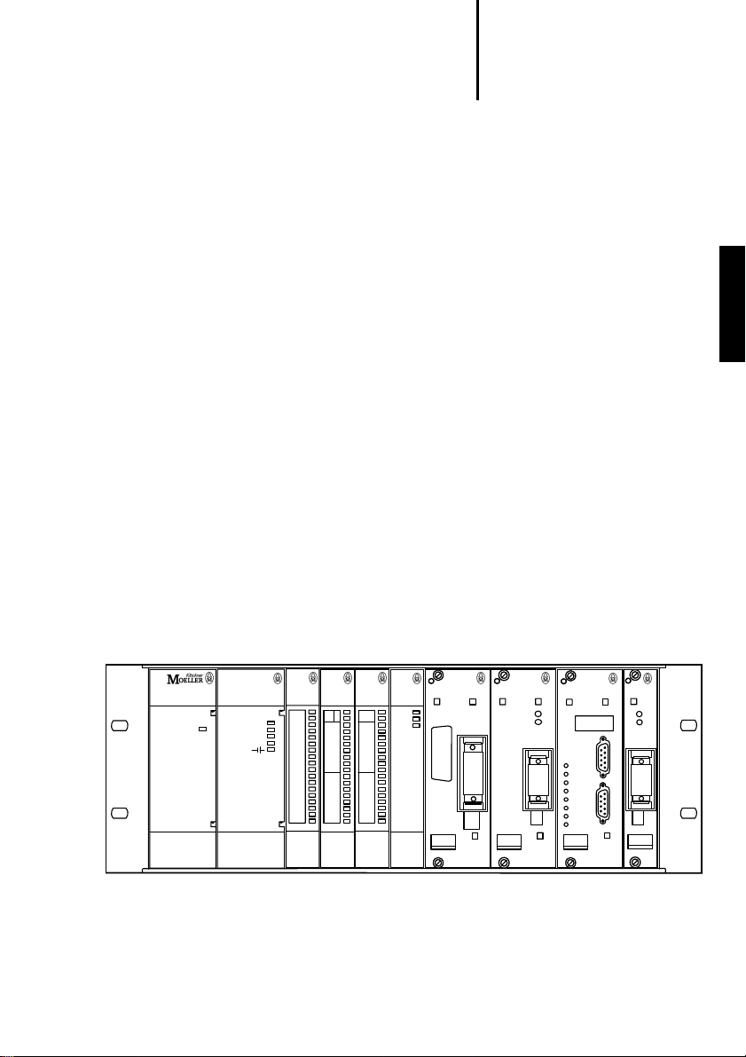
The PS 416 automation system consists of the
following components:
Basic elements
PS 416-BGT-4...rack
PS 416-POW-4x0 power supply card
PS 416-CPU-200/-300/-400/-223 central processing unit
8
02/98 AWB 27-1208-GB
Page 12
Components
For Immediate Delivery call KMParts.com at (866) 595-9616
Standard cards
Digital input/output cards
PS 416-INP-400/401
PS 416-OUT-400/410
Analogue input/output cards
PS 416-AIO-400/PS 416-AIN-400
PS 416-CNT-200 counter card
Networking/communications cards
PS 416-NET-210 Suconet K card
(only with PS 416-CPU-223 central unit)
PS 416-NET-400 Suconet K card
PS 416-NET-230 PROFIBUS card
PS 416-NET-220 Interbus S card
PS 416-COM-200 Communications card
PS 416-COM-200 Communications card
The basic elements, such as rack, power supply and
the central unit are described in this manual.
The hardware and programming of the
PS 416-CPU-223 are described in the
AWB 27-1243-GB.
PS 416 system
power supply
230 V AC
power
PS 416
POW-400
processing unit
not ready
change
run
ready
error
CPU-400
analog I/O
4xI, 4xQ, 12Bit
AIO-400
digital in
I
I
INP-400
digital out
Reset
Q
Q
OUT-400
network
16x0,5A
SUCOnet K
active
ready
ZAA
.0
error
.1
.2
.3
.4
.5
.6
.7
.0
.1
.2
.3
.4
.5
.6
.7
NET-400
16x0,3ms
.0
.1
.2
.3
.4
.5
.6
.7
.0
.1
.2
.3
.4
.5
.6
.7
COUNTER
14
1
GND
CH0
15
2
GND
CH0
16
3
GND
CH1
17
4
GND
CH1
18
5
GND
CH2
19
6
CH2
GND
7
20
CH3
5V
8
21
CH3
5V
9
22
CH4
5V
10
23
CH4
24V
11
24
CH5
24V
12
25
CH5
24V
13
CNT-200
network
PROFIBUS
NET-230
Bus
ERR
Figure 1: PS 416 automation system
02/98 AWB 27-1208-GB
network
InterBus-S
COM
NET-220
RxD/
TxD
ERR
C
F
G
S
U
C
O
n
e
t
S
COM200
diag.-code
ready
clear
out
run
bsa
con
rb
lb
mod
9
Page 13

10
For Immediate Delivery call KMParts.com at (866) 595-9616
02/98 AWB 27-1208-GB
Page 14
2 Configuration
For Immediate Delivery call KMParts.com at (866) 595-9616
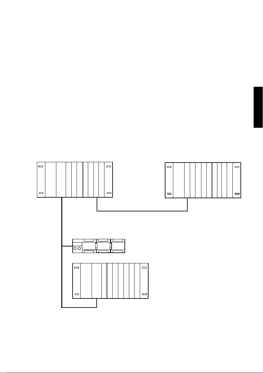
Networks for different applications can be created
with the Suconet K system bus. The network stations
are configured according to their functions. The
following functions are possible:
PS 416 system
AIN
POW
PS 416-CPU-x00
INP
AIN
AIO
OUT
EM 4-201-DX2
POW
NET 400
LE 4116-DX1
AIN
Master
햲
Slaves for the expansion of the remote inputs/
outputs:
Expander rack
Expansion module
Intelligent slaves
햲
LE 4-
햴
116-XD1
INP
AIO
OUT
햳
햴
햵
INP
AIN
AIO
POW
NET 400 (E)
햵
OUT
햳
PS 416-CPU-400
*
Figure 2: Device configuration with Suconet K
*) This network line is not possible with the
PS 416-CPU-200.
02/98 AWB 27-1208-GB
11
Page 15

Configuration
For Immediate Delivery call KMParts.com at (866) 595-9616
Master
The master manages the access to the remote input/
output cards. A master is any card that manages a
network line. In a PS 416 system the
PS 416-CPU-300/-400 and/or PS 416-NET-400 can
be implemented as master. Both cards have a
Suconet K interface. The configuration of the
operating mode and the stations is carried out in the
Sucosoft S 40 Topology Configurator.
A PS 416-CPU-300/-400 central unit can manage up
to nine bus lines. One line is integrated on the card,
whilst other lines can be formed using the
PS 416-NET-400 card.
A P S416-CPU-200 central unit can manage up to
eight bus lines, using the PS 416-NET-400 network
card to connect each line.
The current requirements must be calculated in all
cases for the number of bus lines to be used.
Up to 30 stations can be connected to each line. The
number depends on the memory requirements of
each station in the communication memory of the
master.
12
02/98 AWB 27-1208-GB
Page 16

Slaves for remote I/O
For Immediate Delivery call KMParts.com at (866) 595-9616
expansion
NET 400
NET 400
NET 400
1...30
1...30
NET 400
NET 400
1...30
1...30
1...30
NET 400
NET 400
NET 400
PS 416-CPU-x00
PS 416-POW-4x0
햲
123456789
햳
12345678
햴
1...30
1...30
1...30
1...30
Figure 3: Maximum expansion
햲 Lines with PS 416-CPU-300/-400
Lines with
햳
햴 Stations
PS 416-CPU-200
PS 416 system
Slaves for remote I/O
expansion
Slaves for remote I/O expansion have no individual
central unit. They provide the master their data if
requested but cannot communicate with the master.
The number of data bytes which the slaves occupy in
the communication memory of the master is
predefined. This therefore does not have to be
specified in the configuration.
The slaves are addressed in a 5-point notation based
on the spatial configuration of the stations. The
stations are configured in the Topology Configurator
of Sucosoft S 40. Expander racks or expansion
modules are used as slaves for the remote expansion
of the inputs/outputs.
02/98 AWB 27-1208-GB
13
Page 17

Configuration
For Immediate Delivery call KMParts.com at (866) 595-9616
Expander racks
The remote expansion of the inputs/outputs in a
PS 416 system is implemented with racks which do
not have a CPU (expander racks). The required
configuration parameters of the local inputs/outputs
of these racks are sent to the PS 416-NET-400 card
via the master.
The address set on the card must comply with the
address set in the Sucosoft Topology Configurator.
You will find detailed information on the
PS 416-NET-400 card in the Suconet K Interface
manual, AWB 27-1210-GB.
The PS 416 automation system can process up to
30 expander racks on one line. Up to nine/eight lines
(depending on the CPU) can be managed on each
basic unit. The total permissible number of cards
that can be used on the rack depends on the total
current consumption of the individual cards and the
power supply card used (current consumption
calculation). The standard cards can be used as
components of the expander rack. The
communication is carried out via Suconet K. The
following settings are possible depending on the
application at hand:
Table 2: Application criteria
Baud rate
(Kbaud)
187.5 no 600 m good
187.5 yes 600 m very good
375 no 300 m good
375 yes 300 m very good
1) These bus lengths can only be implemented with the
CRC16 check max. bus
cable listed under Accessories in the appendix.
length
1)
Data saving
14
02/98 AWB 27-1208-GB
Page 18

Intelligent slaves
For Immediate Delivery call KMParts.com at (866) 595-9616
784 bytes of memory are available for the
communication with all connected stations of a line
on the PS 416-CPU-300/-400. The following table
shows the memory assignment of the cards to be
used.
Table 3: Memory assignment of the cards of an expander
rack
Card Input byte Output byte
PS 416-INP-400/401 2 –
PS 416-OUT-400/410 – 2/1
PS 416-AIN-400 16 –
PS 416-AIO-400 8 8
PS 416-CNT-200 12 –
Expansion modules
Expansion modules of the EM... compact series are
usually used for the expansion of remote inputs/
outputs. They do not have their own central unit.
PS 416 system
Intelligent slaves
Intelligent slaves have their own central unit and are
thus able to process their own user program. The
communication between the master and intelligent
slaves is carried out in both directions. The number
of send and receive data bytes for intelligent slaves
must be defined in the Sucosoft S 40 Topology
Configurator. The memory size depends on the type
of slave.
The following components can be used as intelligent
slaves:
02/98 AWB 27-1208-GB
15
Page 19

Table 4: Data exchange memory of intelligent slaves
For Immediate Delivery call KMParts.com at (866) 595-9616
Components Usable memory
PS 416-CPU-300/-400 784 bytes
PS 416-NET-400 1492 bytes
PS 4-101-DD1
PS 4-111-DR1/DR5
PS 4-201-MM1
PS 4-141-MM1
PS 4-151-MM1
PS 4-401-MM2 168 bytes
1) The available memory size depends on the number of
connected slaves on a line. The values stated in the
table apply with the maximum utilization of the line.
6 bytes Master 씮 Slave
7 bytes Slave 씮 Master
Total I/O 78 bytes
1)
The station is addressed by the user program in bit,
byte, word or double word format depending on the
station. The operations with the possible operands
and function blocks are described in the
Sucosoft S 40 programming software.
16
02/98 AWB 27-1208-GB
Page 20

3 Engineering
For Immediate Delivery call KMParts.com at (866) 595-9616
Electromagnetic
compatibility (EMC)
Reaction times
Interference immunity
Observe the engineering instructions in the manual
“EMC Engineering Guidelines for Automation
Systems” (AWB 27-1287-GB)
The shortest reaction time can be implemented with
local cards that are addressed by the central unit via
the internal bus. Only the program cycle time and the
input/output delays of the cards determine the
reaction time.
If remote stations are connected via Suconet K, the
reaction time depends on the number of stations on
the line, the data volume and the data transfer rate.
Further information on the calculation of the reaction
time is given in the Appendix.
The PS 416 system is designed for industrial
applications.
Provide the supply cable of the power supply card
with a ferrite ring. Mounting should be carried out as
close to the card as possible. No further connections
to other devices may be implemented beyond this
point.
PS 416 system
The ferrite ring is not delivered with the cards.
02/98 AWB 27-1208-GB
Please order separately:
Type PS 416-ZBX-405
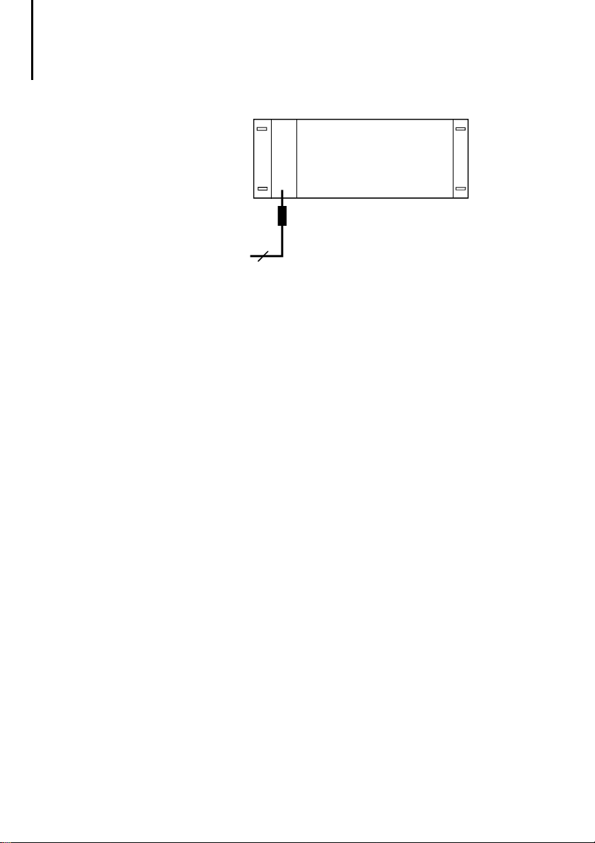
The following figure shows the use of the ferrite ring,
using the PS 416-POW-400 as an example:
17
Page 21
Engineering
For Immediate Delivery call KMParts.com at (866) 595-9616
PS 416
POW-400
Ferrite ring
230 V AC
3
Ensure that all signal cables of communications and
analog cards are laid separately from power and
control cables in order to prevent interference.
Radiated interference
Interference is either caused by radiation or via
electromagentic fields or by static discharges.
Interference signals coming from
fields
can affect signal cables. This can be prevented
by screening these cables. The screen braid here
intercepts the interference potential. The screen
discharge to earth is implemented via high-frequency,
low-impedance connections.
electromagnetic
The screen earth should
be located as close as possible to the most sensitive
location of the system, e. g. on the inputs of the
cards. A potential equalisation bar can therefore be
fitted on the racks of the PS 416 system (see
Appendix). The screen must not be interrupted so
that the conductive plugs and mounting components
which do not belong to the signal circuit on the card
are connected with the screen. They are earthed via
the protective conductor on the rack which is
connected with the central reference point.
Installation notes, see chapter “Racks”.
18
02/98 AWB 27-1208-GB
Page 22

Interference immunity
For Immediate Delivery call KMParts.com at (866) 595-9616
Static discharges
may cause a system fault via
conductive components which do not belong to the
operating circuit (e. g. plugs, switches, mounting
components). All freely accessible components
which are not covered by a flap or covering are
electrically connected to the rack. The guide rails of
the card are provided with contact springs. Ensure
that these contact elements function correctly.
Note
Ensure that you are free of electrostatic charge
when working with operating elements and
components that are covered. This especially
applies to the battery, the memory card and the
operating switches of the CPU.
Line-conducted interference
Line-conducted interference may be due to galvanic,
capacitive and inductive coupling. All cards of the
PS 416 system have appropriate suppressor
elements which ensure the correct functioning of the
cards according to the relevant interference class.
The engineering of the system should not involve any
switchgear with higher interference levels.
Interference sources of this kind must be eliminated
via an appropriate installation or suppressor
elements.
PS 416 system
02/98 AWB 27-1208-GB
19
Page 23

20
For Immediate Delivery call KMParts.com at (866) 595-9616
02/98 AWB 27-1208-GB
Page 24

PS 416-BGT-4.. Racks
For Immediate Delivery call KMParts.com at (866) 595-9616
Contents
1 Racks
Task 23
System description 23
Setup 24
2 Engineering
Coupling the racks 27
Assignment of the rack 27
3 Installation
Fixing the potential equalisation bar 29
Connecting the protective earth 29
Fitting/removing cards 29
4Operation
Monitoring 33
23
PS 416-BGT-4..
27
29
33
02/98 AWB 27-1208-GB
21
Page 25

22
For Immediate Delivery call KMParts.com at (866) 595-9616
02/98 AWB 27-1208-GB
Page 26

1 Racks
For Immediate Delivery call KMParts.com at (866) 595-9616
Task
System description
The PS 416-BGT-4.. racks are used for the assembly
of PS 416 programmable controllers.
The racks house mechanically and electrically house
the individual cards. They provide protection against
mechanical and electromagnetic interference. An
internal bus is used for the power supply and the
signal exchange between the cards. An integrated
monitoring element monitors the 5 V system voltage
and the bus activity and generates an Enable signal
(ENA) for the cards.
Fully mounted devices for installation on a mounting
plate are available in three different sizes as well as a
rack for front installation. The following table shows
the mounting type and the number of the freely
available slots in the individual racks.
Table 5: Type overview of racks
Type Installation type Number of free slots
PS 416-BGT-400 Mounting plate 9
PS 416-BGT-410 Mounting plate 13
PS 416-BGT-420 Mounting plate 19
PS 416-BGT-421 Front mounting 19
PS 416-BGT-4..
02/98 AWB 27-1208-GB
23
Page 27
Racks
For Immediate Delivery call KMParts.com at (866) 595-9616
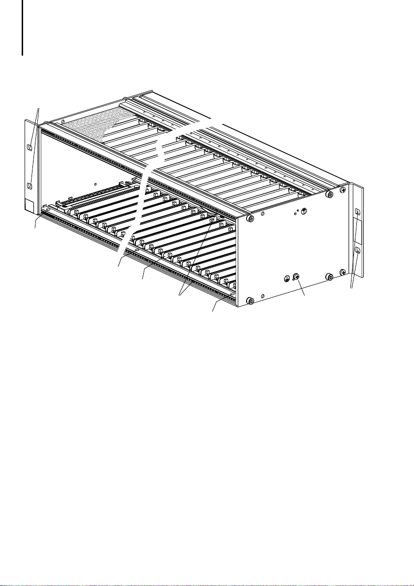
Setup
햲
햴
햴
햶
햵
햴
햳
햲
Figure 4: Setup of the racks for mounting plate installation
(left) and front mounting (right)
햲 Fixing holes for mounting/installation of the rack
햳 Protective earth connection (PE)
햴 Fixing holes for the potential equalisation bar
햵 Fast-release lock for fixing the card
햶 Rails for inserting the card
24
02/98 AWB 27-1208-GB
Page 28
PS 416-BGT-4xx
For Immediate Delivery call KMParts.com at (866) 595-9616
햲
햳
M4
8
´
Setup
Potential equalisation bar
A suitable potential equalisation bar is supplied with
each rack as an accessory. The bar is used for
connecting the cable screens to the protective earth.
Table 6 shows an overview of potential equalisation
bars for the individual racks.
Table 6: Type overview potential equalisation bars
Racks Potential equalisation bar
PS 416-BGT-400 PS 416-ZBX-403
PS 416-BGT-410 PS 416-ZBX-402
PS 416-BGT-420, PS 416-BGT-421 PS 416-ZBX-401
PS 416-ZBX-40x
M4
´
12
PS 416-BGT-4..
햴
PS 416-ZBX-404
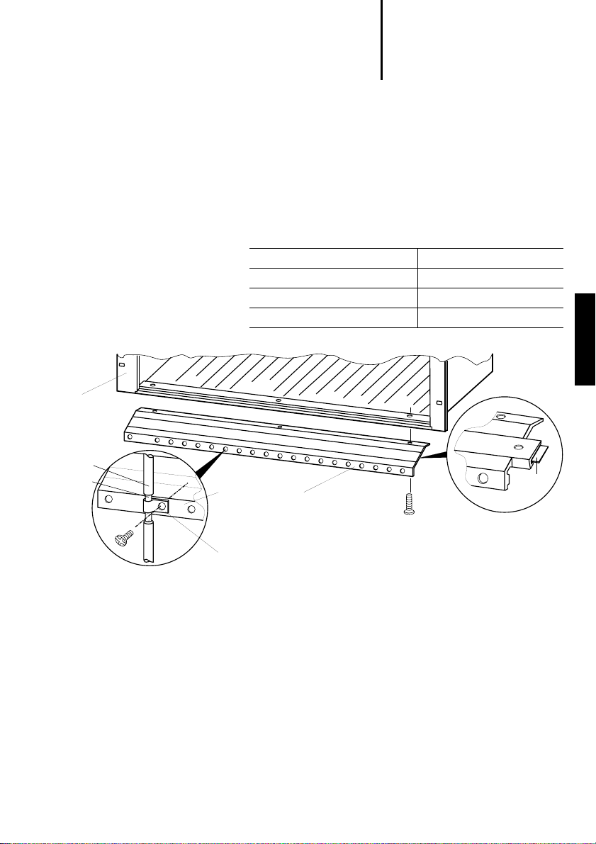
Figure 5: Setup and mounting of the potential equalisation
bar
햲 Cable
햳 Screen
햴 Marking strip
02/98 AWB 27-1208-GB
25
Page 29

26
For Immediate Delivery call KMParts.com at (866) 595-9616
02/98 AWB 27-1208-GB
Page 30

2 Engineering
For Immediate Delivery call KMParts.com at (866) 595-9616
All racks can be used as a basic unit (with central
unit) or as an expander rack (without central unit).
Each rack must be fitted with a power supply card
which must always be fitted in the left "POW" slot.
The other slots can be used as required.
Coupling the racks
Assignment of the rack
The coupling between the basic unit and expander
rack is carried out via the Suconet K field bus. The
internal bus in the basic unit is operated by the
central unit, in the expander by the PS 416-NET-400
Suconet K card. You will find a detailed description
of coupling with PS 416-NET-400 in the “Suconet K
interface” manual AWB 27-1210-GB.
All card types can be used in a rack.
The PS 416-NET-400 card is used in the expander
rack for coupling to the basic unit and for controlling
the internal bus. Only standard cards must be used
in an expander rack:
Digital input/output cards
Analogue input/output cards
Counter card
PS 416-BGT-4..
02/98 AWB 27-1208-GB
27
Page 31

Engineering
For Immediate Delivery call KMParts.com at (866) 595-9616
Figure 6 shows the possible assignments of the rack
for the individual cards.
햲
PS 416-POW-4x0
PS 416-CPU-
200/-300/-400
PS 416-...
햳
PS 416-POW-4x0
PS 416-NET-400
PS 416-...
POW
234 10 14 20
PS 416-BGT-420/421
PS 416-BGT-410
PS 416-BGT-400
234 10 14 20
POW
... ... ...
... ... ...
Figure 6: Slot assignment in the basic unit 햲 and the
expander rack 햳
1 slot = 4 space units (1 space unit = 5.08 mm)
28
02/98 AWB 27-1208-GB
Page 32

3 Installation
For Immediate Delivery call KMParts.com at (866) 595-9616
The PS 416-BGT-400/410/420 racks are directly
installed on a mounting plate in a control cabinet. The
PS 416-BGT-421 rack can be installed via the
mounting brackets on the front in a 19-inch mounting
rail system or swing frame.
Use type M6҂25 screws for installing the rack on
the mounting plate or for front installation.
PS 416-BGT-4..
Fixing the potential
equalisation bar
Connecting the
protective earth
Fitting/removing cards
Fix the equalisation bar with three M4҂12 screws
왘
on the bottom of the rack before mounting.
The protective earth (PE) can be connected on the
side of each rack.
Connect the protective earth via the M4҂4 screw
왘
(see also section “Interference immunity”).
Note
Only fit or remove the cards with the PLC
switched off.
Voltage peaks on the bus connector may otherwise
cause interference or may damage the controller or
the card.
02/98 AWB 27-1208-GB
29
Page 33

Installation
For Immediate Delivery call KMParts.com at (866) 595-9616
Installation
Fit the cards into the rack:
왘
the PS 416-POW-4x0 power supply card
into the “POW” slot,
the PS 416-CPU-200/-300/-400 central unit
into the slots 2 and 3, the Suconet K card
into the slot 2,
all other cards into any available slot.
Insert the card into the rack until you hear the
왘
spring lug snap into position.
Wire the card. Refer to the “Hardware and
왘
Engineering” manual for the card concerned.
Removing
Open the front cover.
왘
Remove the cables.
왘
Unlock the spring lug by pressing the lever
왘
(see arrow in Figure 7).
Pull the card forward towards you.
왘
30
02/98 AWB 27-1208-GB
Page 34

Fitting/removing cards
For Immediate Delivery call KMParts.com at (866) 595-9616
PS 416-BGT-4..
L1
N
PE
A
C
B
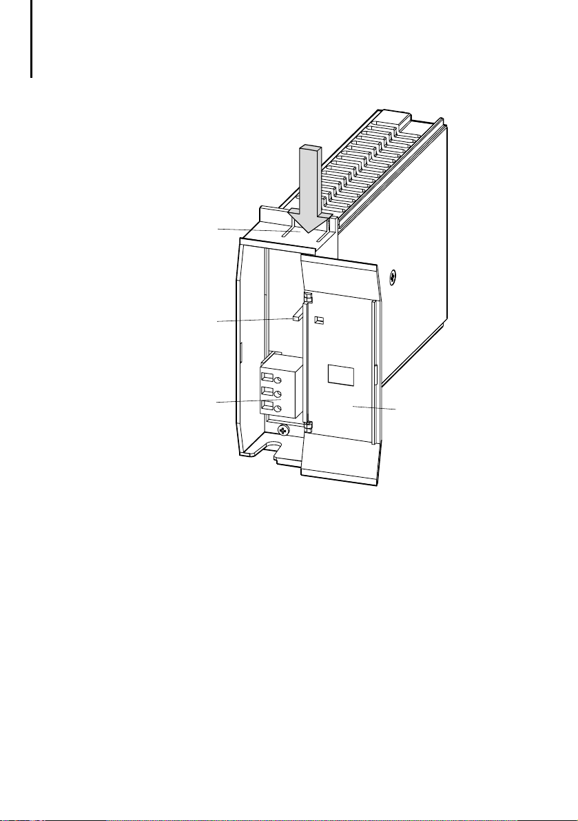
Figure 7: Installing/removing cards. The PS 416-POW-400
power supply card as an example
02/98 AWB 27-1208-GB
31
Page 35

32
For Immediate Delivery call KMParts.com at (866) 595-9616
02/98 AWB 27-1208-GB
Page 36

4 Operation
For Immediate Delivery call KMParts.com at (866) 595-9616
Monitoring
During operation, the rack monitors the 5 V system
voltage. The function cards are disabled if the system
voltage falls below the permissible minimum of
4.75 V.
The rack also monitors the control of the internal bus
by the central unit (basic unit) or the
PS 416-NET-400 Suconet K card (expander rack).
The voltage is switched off and the function cards are
disabled if no activity is on the bus for approx.
100 ms. In both cases all outputs are reset.
PS 416-BGT-4..
02/98 AWB 27-1208-GB
33
Page 37

34
For Immediate Delivery call KMParts.com at (866) 595-9616
02/98 AWB 27-1208-GB
Page 38

PS 416-POW-400/410/420
For Immediate Delivery call KMParts.com at (866) 595-9616
Power Supply Cards
Contents
1 About the power supply card
Task 37
Setup 37
2 Engineering
Number of power supply cards 42
Mains filter 42
Connection assignment 42
Wiring PS 416-POW-400/-420 44
Wiring PS 416-POW-410 47
Cabling 49
3 Installation
Connecting the mains supply 51
4Operation
Function of the card 53
5 Diagnostics
37
41
PS 416-POW-4x0
51
53
55
02/98 AWB 27-1208-GB
35
Page 39

36
For Immediate Delivery call KMParts.com at (866) 595-9616
02/98 AWB 27-1208-GB
Page 40

1 Power Supply Card
For Immediate Delivery call KMParts.com at (866) 595-9616
Task
Setup
The PS 416-POW-4x0 power supply card generates
the 5 V stabilised system voltage required for the
operation of the PS 416 automation system from the
connected mains supply. The power supply card
also monitors the power supply for voltage failures.
The PS 416-POW-4x0 power supply card can be
operated in all racks of the PS 416 automation
system.
PS 416-POW-4x0
02/98 AWB 27-1208-GB
37
Page 41
Power Supply Card
For Immediate Delivery call KMParts.com at (866) 595-9616
햲
햵
L
1
햴
N
P
E
햳
Figure 8: Setup of the PS 416-POW-400 and
PS 416-POW-420 cards
햲 Spring lug
햳 Front cover
햴 Screw terminal for power supply
PS 416-POW-400 L1/N: 230 V AC
PS 416-POW-420 L1/N: 115 V AC
PS 416-POW-400/420 PE: protective earth
햵 LED for mains supply
38
02/98 AWB 27-1208-GB
Page 42

Setup
For Immediate Delivery call KMParts.com at (866) 595-9616
햲
햵
02/98 AWB 27-1208-GB
2
4
V
0
햴
V
햳
Figure 9: Setup of the PS 416-POW-410 card
햲 Spring lug
햳 Front cover
햴 Screw terminal for power supply
24 V/0 V: 24 V DC
PE: protective earth
햵 LED for mains supply
PS 416-POW-4x0
39
Page 43

40
For Immediate Delivery call KMParts.com at (866) 595-9616
02/98 AWB 27-1208-GB
Page 44

2 Engineering
For Immediate Delivery call KMParts.com at (866) 595-9616
Ensure that the relevant safety regulations and
accident prevention requirements (EN, IEC
regulations) are observed if required.
With 24 V supplies the low voltages must be isolated
electrically. Only power supply units produced
according to IEC 364-4-41 must be used.
Emergency-stop devices according to
EN 60204/IEC 204 must be functional in all operating
modes of the controller. Unlocking the Emergencystop device must not cause an uncontrolled or
undefined restart.
02/98 AWB 27-1208-GB
Please observe the technical data of the
PS 416-POW-4x0 card (see Appendix) when
engineering.
PS 416-POW-4x0
41
Page 45

Engineering
For Immediate Delivery call KMParts.com at (866) 595-9616
Potential isolation
Number of power
supply cards
Overvoltage
Filter
L1
N
PE
Power
PS 416-POW-400/420
Figure 10: Block diagram for the PS 416-POW-4x0 power
supply card
protection
Control
unit
HF
transformer
Overvoltage
protection
Power Fail Indicator
Each rack requires one power supply card. The fitting
of several power supply cards on one rack is not
possible.
5 V/
8 A
Mains filter A mains filter is not required due to filter measures
already integrated.
42
02/98 AWB 27-1208-GB
Page 46

Connection assignment
For Immediate Delivery call KMParts.com at (866) 595-9616
Connection
assignment
The card is connected to the mains supply via a
3-pole screw terminal which is located behind the
front cover.
2
4
L
1
N
P
E
Figure 11: Terminal for mains supply
Left: Terminal block for a voltage of
230 V AC (PS 416-POW-400)
115 V AC (PS 416-POW-420)
Right: Terminal block for a voltage of
24 V DC (PS 416-POW-410)
Table 7: Meaning of the connections
PS 416-POW-... Connection Meaning
... 400 L1, N
PE
... 410 24 V, 0 V댸Rated voltage 24 V DC,
... 420 L1, N
PE
V
0
V
Rated voltage 230 V AC, single
phase,
195 to 264 V AC/47 to 400 Hz
Rated current max. 0.5 A
Protective conductor
19.2 to 30 V DC
Rated current approx. 3 A
Protective conductor
Rated voltage 115 V AC, single
phase,
98 to 132 V AC/47 to 400 Hz
Rated current approx. 1 A
Protective conductor
PS 416-POW-4x0
02/98 AWB 27-1208-GB
43
Page 47

Engineering
For Immediate Delivery call KMParts.com at (866) 595-9616
Wiring
PS 416-POW-400/-420
Figure 12 shows the direct connection of the mains
supply to the PS 416-POW-400/420 power supply
cards.
L1
L2
L3
N
PE
F1
PS 416-POW-400/420
PS 416
L1
N
햲
Figure 12: Direct connection of the mains supply 230 V
or 115 V AC
PE
햲 PS 416-ZBX-405 ferrite ring
Mounting see “Cabling” on page 49.
The ferrite ring is not supplied with the card.
Please order separately.
With applications which must meet the EN 60204-1
requirements the connection is carried out via a
control transformer. Figure 13 shows the external
wiring of the P S416-POW-400/420 power supply
cards with earthed operation, figure 14 with
unearthed operation.
44
02/98 AWB 27-1208-GB
Page 48

For Immediate Delivery call KMParts.com at (866) 595-9616
Wiring
PS 416-POW-400/-420
An isolation monitoring device must be
implemented with unearthed mains supply
(EN 60 204-1).
L1
L2
L3
N
PE
Q1
I > I > I >
MM
F1
PS 416-POW-4x0
PS 416
햲
Figure 13: Connection of the mains supply 230 or 115 V AC
via control transformer with earthed operation
햲 PS 416-ZBX-405 ferrite ring
Mounting see “Cabling” on page 49.
The ferrite ring is not supplied with the card.
Please order separately.
02/98 AWB 27-1208-GB
PS 416-POW-400/420
L1
N
PE
45
Page 49

Engineering
For Immediate Delivery call KMParts.com at (866) 595-9616
L1
L2
L3
N
PE
F3
Q1
I > I > I >
S1
K1
MM
F2
F1
P1
PS 416
햲
S2
P1
K1
Isolation
monitoring
PS 416-POW-400/420
L1
N
PE
Figure 14: Connection of the mains supply 230 or 115 V AC
via control transformer with unearthed operation
햲 PS 416-ZBX-405 ferrite ring
Mounting see “Cabling” on page 49.
The ferrite ring is not supplied with the card.
Please order separately.
46
02/98 AWB 27-1208-GB
Page 50

Wiring PS 416-POW-410
For Immediate Delivery call KMParts.com at (866) 595-9616
Wiring
PS 416-POW-410
Figure 15 shows the external wiring of the
PS 416-POW-410 power supply card with earthed
operation; figure 16 with unearthed operation.
An isolation monitoring device must be
implemented with unearthed mains supply
(EN 60 204-1).
L1
L2
L3
N
PE
Q1
G1
I >I >I >
3
0 V
+24 V
PS 416-POW-4x0
F1
Figure 15: Connection of the 24 V DC mains supply,
earthed operation
02/98 AWB 27-1208-GB
PS 416-POW-410
PS 416
24 V
0 V
47
Page 51

Engineering
For Immediate Delivery call KMParts.com at (866) 595-9616
L1
L2
L3
N
PE
F3
Q1
I > I > I >
S1
K1
G1
S2
Isolation
monitoring
24 V
0 V
P1
K1
3
0 V
+24 V
F2
F1
P1
PS 416-POW-410
PS 416
Figure 16: Connection of the 24 V DC mains supply,
unearthed operation
48
02/98 AWB 27-1208-GB
Page 52

Cabling
For Immediate Delivery call KMParts.com at (866) 595-9616
Cabling Use a 3-core cable (with protective conductor) for
the connection of the mains supply.The core cross-
2
section must not exceed 1.5 mm
(solid or flexible).
왘 Connect twisted mains cables and with a
sufficient distance to power cables in order to
prevent inductive interference.
왘 Fit ferrite rings to the voltage supply cables of the
AC power supply cards PS 416-POW-400 and
PS 416-POW-420. Fit these ferrite rings as close
to the card as possible directly underneath the
potential equalisation bar.
햲
PS 416-POW-4x0
햳
PS 416-POW-400/420
PS 416-CPU-X00
햶
햵
Figure 17: Mounting the ferrite ring on the
PS 416-POW-400 und P S416-POW-420 cards
Rack
햲
Ferrite ring
햳
Cable binder
햴
Supply cable
햵
Potential equalisation bar
햶
02/98 AWB 27-1208-GB
햴
49
Page 53

50
For Immediate Delivery call KMParts.com at (866) 595-9616
02/98 AWB 27-1208-GB
Page 54

3 Installation
For Immediate Delivery call KMParts.com at (866) 595-9616
Connecting the mains
supply
Observe the following safety instructions before
connecting the power supply card!
Caution
Ensure that the mains connection cables are
de-energized before connecting them to the
power supply card. Always connect the
protective earth conductor. A protective
conductor that is not connected may be
dangerous to persons and machine/system!
Connect the protective conductor and the mains
왘
supply cables to the 3-pole terminal block of the
power supply card. Ensure that the polarity is
correct.
Secure the connection by the integrated screws.
왘
Note
Only operate the card with the permissible rated
voltage (see Technical data), otherwise the card
may be destroyed!
Re-check the wiring before switching on the
왘
supply!
PS 416-POW-4x0
02/98 AWB 27-1208-GB
51
Page 55

52
For Immediate Delivery call KMParts.com at (866) 595-9616
02/98 AWB 27-1208-GB
Page 56

4 Operation
For Immediate Delivery call KMParts.com at (866) 595-9616
Function of the card
The power supply card generates the 5 V DC
stabilised system voltage once the mains supply is
switched on. The regulated voltage is potentially
isolated from the mains supply. The card operates as
a switched mode power supply unit in compliance
with protection class 1. The output current is 1.5 to
8 A (PS 416-POW-400/420) and 1.5 to 10 A
(PS 416-POW-410). The voltage output of the card is
short-circuit and idle-proof.
During operation the card monitors the connected
mains supply. The card generates a warning signal
(PFI = Power Fail Indication) for the central unit in the
event of a mains supply failure that lasts more than
13 ms. This signal initiates a data backup in the
retentive memory of the central unit.
PS 416-POW-4x0
02/98 AWB 27-1208-GB
53
Page 57

54
For Immediate Delivery call KMParts.com at (866) 595-9616
02/98 AWB 27-1208-GB
Page 58

5 Diagnostics
For Immediate Delivery call KMParts.com at (866) 595-9616
The LED on the front is lit if the connected supply is
active.
If the LED is not lit, check whether:
the mains supply is switched on
the fuse for the supply voltage has blown
the wiring is correct.
If the LED indicates that the mains supply is present,
and the system voltage is missing, this may be due
to the following:
the power supply card is not fitted properly in the
rack.
Switch off the mains supply and insert the
왘
card until you hear the card snap into position.
the card has a short-circuit or fault
Switch off the mains supply.
왘
Contact your Moeller sales office.
왘
PS 416-POW-4x0
The system voltage is not directly indicated via a
LED. If none of the LED on all the cards (except
power supply card) fitted in the rack are lit and the
mains supply is correctly applied to the power supply
card, the system voltage is missing.
02/98 AWB 27-1208-GB
55
Page 59

56
For Immediate Delivery call KMParts.com at (866) 595-9616
02/98 AWB 27-1208-GB
Page 60

PS 416-CPU-200/-300/-400
For Immediate Delivery call KMParts.com at (866) 595-9616
Central Unit
Contents
1 About the Central Unit
Task 59
Setup 59
2 Engineering
Slot 69
Power supply 69
Interfaces 69
PRG interface 69
SBI interface (only PS 416-CPU-300/-400) 75
Screening/potential equalisation 78
3 Hardware Configuration
Setting the PRG address 79
Selecting the PRG interface 81
Switching on the PRG terminating resistors 81
Selecting SBI interface
(PS 416-CPU-300/-400 only) 83
4 Installation
ESD measures 87
Fitting the backup battery 87
Changing the backup battery 87
Fitting/removing the memory card 88
Changing the reserve battery 90
Changing the MC battery 91
59
69
79
PS 416-CPU-200/-300/-400
87
5Operation
ESD measures 93
Memory elements 97
Memory card 98
Function 99
Startup behaviour 102
02/98 AWB 27-1208-GB
93
57
Page 61

Contents
For Immediate Delivery call KMParts.com at (866) 595-9616
Stop of the user program 103
Restart behaviour 103
6 Test/Commissioning/Diagnostics
LED display 105
Self test 105
Loading the operating system 105
Loading the user program 106
Error messages 107
Acknowledging errors on NOT-READY 108
Clearing the diagnostic status word 108
Saving data after a battery failure 108
Checking the connection between
PLC and PRG 109
7 Direct Communication with Data Terminal
Units via the COM Function Block
Structure of the COM function block 112
Inputs of the COM function block 113
Outputs of the COM function block 114
Addressing the COM function block 114
Refreshing inputs/outputs 117
Reset behaviour 117
Startup behaviour 118
Data transfer 118
Transparent mode 1 118
Data block length 119
Setting COM function block parameters 119
Starting a job 120
Sending data 120
Receiving data 121
Monitoring a job 122
Aborting a job 122
Test and commissioning 124
Testing the user program 124
Error diagnostics 124
SlotError 125
Error messages 126
105
111
58
02/98 AWB 27-1208-GB
Page 62

1 Central Unit
For Immediate Delivery call KMParts.com at (866) 595-9616
Task
Setup
The central unit controls and monitors the
automation process. It stores and processes the user
program and manages the data exchange with the
connected slaves. The central unit is provided with
the required interfaces for communication,
programming and data exchange.
The central unit consists of two printed circuit boards
and occupies two slots in the rack (= 8 space units).
PS 416-CPU-200/-300/-400
02/98 AWB 27-1208-GB
59
Page 63

Central Unit
For Immediate Delivery call KMParts.com at (866) 595-9616
햲
PS 416-ZBB-410
PS 416-CPU-200
햵
PS 416-ZBB-410
햴
햳
햶
Figure 18: Setup of the PS 416-CPU-200
햲 Plug-in backup battery (on the front)
햳 Spring lug
햴 Switch for bus terminating resistors (PRG: RS 485)
햵 Plug-in reserve battery (internal)
햶 Address switch (PRG)
60
02/98 AWB 27-1208-GB
Page 64

Setup
For Immediate Delivery call KMParts.com at (866) 595-9616
햲 Plug-in backup battery (on the front);
for saving the data if the operating voltage fails (see
sections “Installation”, “Operation”).
햳 Spring lug: Push down before removing
햴 Switch for bus terminating resistors (PRG: RS 485);
for activating/de-activating the bus terminating
resistors if the PRG interface is operated in RS 485
mode (see section “Hardware configuration”).
햵 Plug-in reserve battery (internal);
used as fail-safe battery of the backup battery
(see sections “Installation”, “Operation”).
햶 Address switch (PRG);
for setting the station address under which the central
unit is addressed by the programming device if the
interface is operated in the RS 485 mode
(see section “Hardware configuration”).
Maximum capacity of the
user memory
:
PS 416-CPU-200 256 Kbyte
The operating system has a permanently reserved
memory range.
PS 416-CPU-200/-300/-400
02/98 AWB 27-1208-GB
61
Page 65

Central Unit
For Immediate Delivery call KMParts.com at (866) 595-9616
햲
햳
SET
햴
햻
햺
¬
232
®
485
M
E
M
O
R
Y
C
A
R
D
RUN
READY
NOT READY
ERROR
CHANGE
PRG-BUS-ADDR.
햵
햶
햷
햸
햹
HALT
RUN
PRG
RUN
M-RESET
Figure 19: Setup of the PS 416-CPU-200 central unit
(front view)
햲 Plug-in backup battery
햳 Multi-function button
햴 LED display
햵 Front cover
햶 Space for marking strip
햷 Socket for memory card
햸 Eject button for memory card
햹 Operating mode selector switch
햺 Selector switch for PRG interface (RS 232/RS 485)
햻 PRG interface
62
02/98 AWB 27-1208-GB
Page 66

Setup
For Immediate Delivery call KMParts.com at (866) 595-9616
햳 Multi-function button;
enables several system functions in conjunction with
the operating mode selector switch
(see section “Operation”).
햴 LED display;
indicates the states of the CPU (see section “Test/
Commissioning/Diagnostics”).
햵 Space for marking strip;
the currently set PRG bus address can be written here
(see “Hardware configuration”).
햶 Socket for memory card;
can be used for different functions. Fitting/removing is
described in section “Installation”, the function is
described in section “Operation”.
햷 Eject button for memory card;
pressing this button ejects the memory card.
햸 Operating mode selector switch;
defines the start behaviour of the central unit
(see section “Operation”).
햹 Selector switch for PRG interface (RS 232/RS 485);
with this switch you control whether the connection
to the programming device is carried out via a point-topoint connection (RS 232) or in the RS 485 mode
(see section “Hardware configuration”).
햺 PRG interface;
for the connection to a programming device
(see chapter “Engineering”).
PS 416-CPU-200/-300/-400
02/98 AWB 27-1208-GB
63
Page 67

햲
For Immediate Delivery call KMParts.com at (866) 595-9616
PS 416-ZBB-410
PS 416-CPU-300/-400
햵
PS 416-ZBB-410
햴
햳
햶
햷
Figure 20: Setup of the PS 416-CPU-300/-400
central unit
햲 Plug-in backup battery (front)
햳 Spring lug
햴 Switch for bus terminating resistors (PRG: RS 485)
햵 Plug-in reserve battery (internal)
햶 Switch for bus terminating resistors (SB: RS 485)
햷 Address switch (PRG)
64
02/98 AWB 27-1208-GB
Page 68

햲 Plug-in backup battery (on the front);
For Immediate Delivery call KMParts.com at (866) 595-9616
for saving the data if the operating voltage fails (see
sections “Installation”, “Operation”).
햳 Spring lug: Push down before removing
햴 Switch for bus terminating resistors (PRG: RS 485);
for activating/de-activating the bus terminating
resistors if the PRG interface is operated in RS 485
mode (see section “Hardware configuration”).
햵 Plug-in reserve battery (internal);
used as fail-safe battery of the backup battery
(see sections “Installation”, “Operation”).
햶 Switch for bus terminating resistors (SBI: RS 485);
for activating/de-activating the bus terminating
resistors if the SBI interface is operated in RS 485
mode (see section “Hardware configuration”).
햷 Address switch (PRG);
for setting the station address under which the central
unit is addressed by the programming device if the
interface is operated in the RS 485 mode
(see section “Hardware configuration”).
Maximum capacity of the
user memory
PS 416-CPU-300 512 Kbyte
PS 416-CPU-400 1 MByte
The operating system has a permanently reserved
memory range.
02/98 AWB 27-1208-GB
:
PS 416-CPU-200/-300/-400
65
Page 69

Central Unit
For Immediate Delivery call KMParts.com at (866) 595-9616
햲
SET
햽
햻
햺
¬
232
®
485
PRG
¯
SBI
HALT
RUN
RUN
M-RESET
M
E
M
O
R
Y
C
A
R
D
RUN
READY
NOT READY
ERROR
CHANGE
PRG-BUS-ADDR.
Figure 21: Setup of the PS 416-CPU-300/-400
central unit (front view)
햳
햴
햵
햶
햷
햸
햹
햲 Plug-in backup battery
햳 Multi-function button
햴 LED display
햵 Front cover
햶 Space for marking strip
햷 Socket for memory card
햸 Eject button for memory card
햹 Operating mode selector switch
햺 SBI-Interface
햻 Selector switch for PRG interface (RS 232/RS 485)
햽 PRG interface
66
02/98 AWB 27-1208-GB
Page 70

Setup
For Immediate Delivery call KMParts.com at (866) 595-9616
햳 Multi-function button;
enables several system functions in conjunction with
the operating mode selector switch
(see section “Operation”).
햴 LED display;
indicates the states of the CPU (see section “Test/
Commissioning/Diagnostics”).
햶 Space for marking strip;
the currently set PRG bus address can be written here
(see “Hardware configuration”).
햷 Socket for memory card;
can be used for different functions. Fitting/removing is
described in section “Installation”, the function is
described in section “Operation”.
햸 Eject button for memory card;
pressing this button ejects the memory card.
햹 Operating mode selector switch;
defines the start behaviour of the central unit
(see section “Operation”).
햺 SBI Interface;
for connecting to the Suconet K/K1 fieldbus (see
section "“Engineering” on page 69). A DTE unit can be
connected here in Transparent mode.
햻 Selector switch for PRG interface (RS 232/RS 485);
with this switch you control whether the connection
to the programming device is carried out via a point-topoint connection (RS 232) or in the RS 485 mode
(see section “Hardware configuration”).
햽 PRG interface;
for the connection to a programming device
(see chapter “Engineering”).
PS 416-CPU-200/-300/-400
02/98 AWB 27-1208-GB
67
Page 71

68
For Immediate Delivery call KMParts.com at (866) 595-9616
02/98 AWB 27-1208-GB
Page 72

2 Engineering
For Immediate Delivery call KMParts.com at (866) 595-9616
Slot
Power supply
Interfaces
PRG interface
The slots 2 and 3 are provided for the central unit.
The central unit is supplied by the power supply unit
in the rack. Power consumption, see Technical data
in the Appendix.
PS 416-CPU-200
A programming (PRG) interface is located on the
front of the card. It is isolated for increased
interference immunity.
PS 416-CPU-300/-400
Two interfaces are provided on the front of the card
for programming and networking. They are isolated
for increased interference immunity.
The central unit is connected to the programming
device via the PRG interface. The PRG interface can
be set as an RS 232/RS 485 interface according to
the application at hand (see section “Hardware
configuration”).
PS 416-CPU-200/-300/-400
PRG interface/RS 232
A point-to-point connection with the programming
device (PRG) is possible via the RS 232 interface.
Transfer security is restricted due to possible direct
coupling with the earth potential so that faults may
occur with high transfer speeds. The parameters for
the transfer rate (baud rate) are set via the connection
window in the Test and Commissioning tool of
02/98 AWB 27-1208-GB
69
Page 73

Engineering
For Immediate Delivery call KMParts.com at (866) 595-9616
Sucosoft S 40. 9600 bit/s is recommended as a
standard value.
A prepared cable is offered as connection cable in
the Accessories.
PC
PS 416-CPU-200/-300/-400
Figure 22: Point-to-point connection
Interface parameters:
The parameters required for operating the interface
are set directly in the Connection List window of the
Sucosoft S 40 test and commissioning tool. For this
the required PLC is selected and opened via Device
Interface Parameters in the Interface Settings
씮
dialog box.
The data format is defined with:
Data bit = 8
Parity = none
Stop bit = 1
70
02/98 AWB 27-1208-GB
Page 74

PRG interface
For Immediate Delivery call KMParts.com at (866) 595-9616
Possible settings are: 2400, 4800, 9600 19200,
38400 and 57600 bit/s. If the CPU is started via a
cold start, the PRG is automatically connected
with the selected baud rate and transfers the new
parameters. If no communication is posible with
these parameters, the connection is aborted and
the CPU must be restarted with new values.
A delay function can be implemented and set in
milliseconds. This can be used for adaptions to
poor connections, such as signal delays
occurring during remote diagnostics via modem.
Figure 23: Setting parameters of the COM1 interface
PRG interface/RS 485
Longer distances can be bridged between the
programming device and the PS 416 controller when
using the RS 485 mode of the PRG interface
(see Technical data in the Appendix).
In this case the interface converter U M1.5 must be
connected in series in order to create a connection
between the RS 485 interface on the CPU and the
RS 485 interface of the programming device.
02/98 AWB 27-1208-GB
PS 416-CPU-200/-300/-400
71
Page 75

Engineering
For Immediate Delivery call KMParts.com at (866) 595-9616
If the RS 485 interface cable is lengthened, the
UM1.5 interface converter must be provided a
separate 5 V DC power supply.
PC
UM 1.5
Figure 24: Connection between programming device and
PS 416 controller in RS 485 mode
Pin assignment
PRG
5
+5 V
TB/RB
9
8
7
6
4
3
2
1
SGND
PGND
TxD/TA/RA
RxD
Figure 25: Programming interface, top view
72
02/98 AWB 27-1208-GB
Page 76

PRG interface
For Immediate Delivery call KMParts.com at (866) 595-9616
The table shows the meaning of the signals
depending on the selected interface.
Note
Pin 9 is assigned to the + 5V internal power
supply and Pin 5 is assigned to ground (internal
chassis). These pins must not be connected
otherwise this will destroy the card.
Table 8: Meaning of signals
Pin RS 232 RS 485 Function
1–––
2 RxD – Receive data
3TxD
TA/RA
4 – PGND Potential ground over 100 Ω
5 SGND SGND Signal ground for interface
6–––
7 – TB/RB Send/receive data
8–––
9 – +5 V Voltage for interface converter
Send data
Send/receive data
converter UM 1.5
UM 1.5
PS 416-CPU-200/-300/-400
Wiring
PRG interface/RS 232:
The following figure shows how the PRG interface/
RS 232 on the CPU is connected with the RS 232
interface of the programming device.
02/98 AWB 27-1208-GB
73
Page 77

PRG/RS232
For Immediate Delivery call KMParts.com at (866) 595-9616
Programming device
PRG/RS 485
Signal
TB/RB
TA/RA
PGND
I/O
I/O
I/O
Signal Signal
RxD
TxD 3
SGND
I/O
Pin
I
2
O
–
5
Screen
TxD
RxD
SGND
(sender)
(receiver)
Figure 26: Wiring of the central unit and programming
device via PRG/RS 232
PRG interface/RS 485:
If the PRG interface on the central unit is used as a
RS 485 interface, the UM 1.5 interface converter
must be used in the connection between the RS 485
interface and the RS 232 interface of the
programming device.
햲
UM 1.5
Pin
7
3
4
–
Screen
Signal Signal
Receiver/
sender
Receiver/
sender
PGND
(if required)
+5 V ext.
NG 31
+5 V DC 220 V AC
RxD
TxD
SGND
Programming device
Signal
(sender)
TxD
(receiver)
RxD
SGND
Figure 27: Wiring of the central unit and the programming
device via PRG/RS 485
햲 Required for lengthening the RS 485 interface
74
02/98 AWB 27-1208-GB
Page 78

SBI interface
For Immediate Delivery call KMParts.com at (866) 595-9616
(only
PS 416-CPU-300/-400)
The communication with the Suconet K stations or
data terminal units is carried out via the SBI interface
of the central unit. Transparent or Suconet K mode
can be set for the SBI interface (see Hardware
configuration), depending on the application at hand.
Suconet K mode
In the Suconet K mode the central unit is operated as
a station of a Suconet K line. The station type
(master/slave) is defined in the Sucosoft S 40
Topology Configurator. The central unit can also
connect expander racks when operating as a master.
You will find further information in the Suconet K
interface manual (AWB 27-1210-GB) or in the
relevant manuals for the remote expansion modules.
Transparent mode
This operating mode provides a serial interface for
the point-to-point communication with a data
terminal unit. The communication is carried out via
the COM function block which is integrated in the
central unit and can be called up via Sucosoft S40.
PS 416-CPU-200/-300/-400
The signal level conversion for other interfaces must
be carried out with appropriate converters. The
UM 1.5 converter is available for an RS 485/RS 232
coupling. The addressing of the interface by the
software is described in section “Operation”.
02/98 AWB 27-1208-GB
75
Page 79

Engineering
For Immediate Delivery call KMParts.com at (866) 595-9616
Pin assignment
SBI
5
+5 V
TB/RB
Figure 28: SBI interface, top view
Table 9: Meaning of signals
Pin RS 485 Function
1 ––
2 ––
3 TA/RA Send/receive data
4 PGND Potential ground over 100 Ω
5 SGND Signal ground for UM 1.5 interface converter
6 ––
7 TB/RB Send/receive data
8 ––
9 +5 V Voltage for UM 1.5 interface converter
9
8
7
6
SGND
4
PGND
3
TA/RA
2
1
Wiring
Figure 26 and 27 show the usual wiring between the
SBI interface on the central unit and the R S485
interface of a Suconet K station or the RS 232
interface of a data terminal unit (RS 232).
76
02/98 AWB 27-1208-GB
Page 80

SBI interface (only PS 416-
For Immediate Delivery call KMParts.com at (866) 595-9616
CPU-300/-400)
.
Note
Pin 9 is assigned to the + 5V internal power
supply and Pin 5 is assigned to ground (internal
chassis). These pins must not be connected
otherwise this will destroy the card.
SBI/RS485
Signal
TB/RB
TA/RA
PGND
I/O
I/O
I/O
SBI/RS 485
Signal
TB/RB
TA/RA 3
PGND
I/O
I/O
I/O
–
Pin
7
4
Screen
Suconet K Stn.
Receiver/sender
Receiver/sender
PGND (if required)
Figure 29: Wiring of central unit and Suconet K station
via SBI/RS 485
햲
UM 1.5
Pin
7
3
4
–
Screen
Signal
Receiver/
sender
Receiver/
sender
PGND
(if required)
+5 V ext.
Signal
RxD
TxD
SGND
NG 31
+5 V DC 220 V AC
Data terminal unit
TxD
(sender)
RxD
(receiver)
SGND
PS 416-CPU-200/-300/-400
Figure 30: Wiring of central unit and data terminal unit
via SBI/RS 485
햲 Required for lengthening the RS 485 interface
02/98 AWB 27-1208-GB
77
Page 81

Screening/potential
For Immediate Delivery call KMParts.com at (866) 595-9616
equalisation
Connect the screen of the data cables with the
왘
potential equalisation bar in order to prevent
interference (for mounting instructions see
chapter “Interference immunity”).
Potential equalisation must be provided between the
two cards when using R S485 interfaces if the
potential difference is greater than 7 V. In this case
use a data cable with at least one additional line. This
potential equalisation line is to be connected with the
PGND connection (pin 4).
Take into account the current carrying capacity of
the additional cables.
78
02/98 AWB 27-1208-GB
Page 82

3 Hardware Configuration
For Immediate Delivery call KMParts.com at (866) 595-9616
Setting the PRG
address
The default address of the programming device
interface is set to 1. The interface can be connected
with the programming device (PRG) if you have
configured an appropriate communication relation in
Sucosoft S40.
Proceed as follows if you wish to use an address for
addressing the programming device:
Set the address via the address switch
왘
(see coding table).
Write the set address on the supplied label and
왘
stick it on the back of the front cover.
Enter the same address in the Sucosoft S 40
programming software as you have set via the
DIP switch on the CPU.
PS 416-CPU-200/-300/-400
02/98 AWB 27-1208-GB
79
Page 83

Hardware Configuration
For Immediate Delivery call KMParts.com at (866) 595-9616
Table 10: Address coding
Address Switch
12345678
1 10000000
2 01000000
3 11000000
4 00100000
5 10100000
6 01100000
7 11100000
8 00010000
9 10010000
10 01010000
11 11010000
12 00110000
13 10110000
14 01110000
15 11110000
16 00001000
17 10001000
18 01001000
19 11001000
20 00101000
21 10101000
22 01101000
23 11101000
24 00011000
25 10011000
26 01011000
27 11011000
28 00111000
29 10111000
30 01111000
31 11111000
80
02/98 AWB 27-1208-GB
Page 84

Selecting the PRG
For Immediate Delivery call KMParts.com at (866) 595-9616
interface
Example
The switch for a CPU with the address 4 is set as
follows:
ON
23456781
Figure 31: Switch position for address 4
Selecting the PRG
interface
Switching on the PRG
terminating resistors
Set the selector switch for the PRG interface as
follows:
Push the switch to the left to connect the
왘
controller directly with the PRG (RS 232).
Push the switch to the right to connect the
왘
controller with the PRG via an interface (RS 485).
RS 232
RS 485
Figure 32: Selector switch in RS 232 setting
In the RS 485 mode the terminating resistors on the
CPU must be switched on (ON). In all other cases the
bus terminating resistors must be inactive (OFF).
PS 416-CPU-200/-300/-400
02/98 AWB 27-1208-GB
81
Page 85

Hardware Configuration
For Immediate Delivery call KMParts.com at (866) 595-9616
Set the poles 1 and 2 of the switch for bus
왘
terminating resistors to position ON.
21
Figure 33: Activated bus terminating resistors
Note
Both poles must always be in the same position
in order to ensure the correct functioning of
the card.
82
02/98 AWB 27-1208-GB
Page 86

Selecting SBI interface
For Immediate Delivery call KMParts.com at (866) 595-9616
(PS 416-CPU-300/-400
only)
Selecting SBI interface
(PS 416-CPU-300/-400
only)
Set the address and the baud rate in the Sucosoft
S 40 Topology Configurator. The following baud
rates are available:
Suconet K mode: 187.5/375 Kbaud
Transparent mode:
300/600/1200/2400/4800/9600/19200 bit/s
Figure 34: Setting the baud rate in Suconet K mode
02/98 AWB 27-1208-GB
PS 416-CPU-200/-300/-400
83
Page 87

Hardware Configuration
For Immediate Delivery call KMParts.com at (866) 595-9616
Figure 35: Setting the baud rate in Transparent mode
84
02/98 AWB 27-1208-GB
Page 88

Selecting SBI interface
For Immediate Delivery call KMParts.com at (866) 595-9616
(PS 416-CPU-300/-400
only)
Switching on the SBI terminating resistors
(PS 416-CPU-300/-400 only)
The terminating resistors of the physically first and
last bus station must be switched on (ON) when the
SBI is run in Suconet K mode. In all other cases the
bus terminating resistors must be inactive (OFF).
Set the poles 1 and 2 of the switch for the bus
terminating resistors to position ON.
21
Figure 36: Activated bus terminating resistors
Note
Both poles of the switch must always be in the
same position in order to ensure correct
functioning of the card.
02/98 AWB 27-1208-GB
PS 416-CPU-200/-300/-400
85
Page 89

86
For Immediate Delivery call KMParts.com at (866) 595-9616
02/98 AWB 27-1208-GB
Page 90

4 Installation
For Immediate Delivery call KMParts.com at (866) 595-9616
ESD measures
Fitting the backup
battery
Changing the backup
battery
Before touching operating elements, interfaces and/
or data connectors during the installation, make sure
that you are free of electrostatic charge by touching
a surface with a good earth (control cabinet, device
frame).
Ensure the following during normal operation ("RUN"
mode):
the front covers should be closed
the front covers should be snapped into position
Proceed as follows to fit the backup battery:
Open the front cover
왘
Insert the battery into the space provided until the
왘
retaining clip snaps into position
Close the front cover
왘
Note
Ensure that a reserve battery is present before
changing the battery in order to prevent data
loss. The reserve battery must be changed every
five years.
PS 416-CPU-200/-300/-400
It is always possible to change the battery with the
operating voltage switched on. If the battery is
changed with the operating voltage switched off, the
voltage must only be switched on with the battery
fitted; otherwise a cold start is initiated and all
programs and data are lost.
02/98 AWB 27-1208-GB
87
Page 91

Installation
For Immediate Delivery call KMParts.com at (866) 595-9616
Open the front cover
왘
Push the retaining clip downwards
왘
Remove the battery
왘
Insert the new battery into the space provided
왘
until the retaining clip snaps into position
Close the front cover
왘
Fitting/removing the
memory card
Fitting
Insert the memory card into the socket until the
왘
eject button appears.
Correct mounting is ensured by a mechanical
lock.
88
02/98 AWB 27-1208-GB
Page 92

Removing
For Immediate Delivery call KMParts.com at (866) 595-9616
Press the eject button and remove the memory
왘
card.
PS 416-ZBB-410
Fitting/removing the
memory card
PS 416-CPU-400
SET
232
485
M
E
M
O
R
Y
C
A
R
D
PRG
SBI
PS 416-MEM-430/440
Figure 37: Fitting/removing the memory card and backup
battery
02/98 AWB 27-1208-GB
HALT
RUN
M-RESET
RUN
PS 416-CPU-200/-300/-400
89
Page 93

Installation
PS 416-ZBB-410
For Immediate Delivery call KMParts.com at (866) 595-9616
Changing the reserve
battery
The reserve battery is not discharged during normal
operation and has a very long lifespan. The battery
must be changed every five years since the central
unit is not provided with a monitoring device for the
battery.
Figure 38: Fitting/removing the reserve battery
90
02/98 AWB 27-1208-GB
Page 94

Changing the MC battery
For Immediate Delivery call KMParts.com at (866) 595-9616
Changing the MC
battery
Proceed as follows to change the MC battery on the
memory card :
1.
2.
PS 416-ZBB-300
3.
4.
PS 416-CPU-200/-300/-400
Figure 39: Changing the MC battery
02/98 AWB 27-1208-GB
91
Page 95

92
For Immediate Delivery call KMParts.com at (866) 595-9616
02/98 AWB 27-1208-GB
Page 96

5 Operation
For Immediate Delivery call KMParts.com at (866) 595-9616
ESD measures
PS 416-CPU-200
Before touching operating elements, interfaces and/
or data connectors during the installation, make sure
that you are free of electrostatic charge by touching
a surface with a good earth (control cabinet, device
frame).
Ensure the following during normal operation ("RUN"
mode):
the front covers should be closed
the front covers should be snapped into position
Realtime
Memory
card
512 KBytes
or
1 MByte
Bus
interface
ASIC
DPR
PS 416
User
program
memory
256 KBytes
Control
processor
RS 485
or
RS 232C
Operating
system
memory
512 KBytes
Voltage
monitoring
System bus
PRG
clock
pluggable/
optional
PS 416-CPU-200/-300/-400
Figure 40: Block diagram of the PS 416-CPU-200
02/98 AWB 27-1208-GB
93
Page 97

Operation
For Immediate Delivery call KMParts.com at (866) 595-9616
The PS 416-CPU-200 contains the following
elements required for the operation of the PS 416
automation system:
Control processor for program processing
Memory elements for operating system,
programs and data
Real-time clock
Interface to parallel bus and bit bus
Batteries for data backup in the event of voltage
drops
Monitoring device for battery function
94
02/98 AWB 27-1208-GB
Page 98

ESD measures
For Immediate Delivery call KMParts.com at (866) 595-9616
PS 416-CPU-300
Memory
card
512 KBytes
or
1 MByte
Bus
interface
ASIC
DPR
User
program
memory
512 KBytes
Control
processor
PS 416
RS 485
or
RS 232C
Operating
system
memory
512 KBytes
System bus
PRG
I/O
processor
RS 485
Suconet K
Transparent mode (COM)
Voltage
monitoring
DPR
Figure 41: Block diagram of the PS 416-CPU-300
Realtime
clock
pluggable/
optional
PS 416-CPU-200/-300/-400
02/98 AWB 27-1208-GB
95
Page 99

Operation
For Immediate Delivery call KMParts.com at (866) 595-9616
PS 416-CPU-400
Real-
Memory
card
(optional)
Bus
interface
ASIC
DPR
Figure 42: Block diagram PS 416-CPU-400
PS 416
Memorycard
(optional)
Control
processor
RS 485
or
RS 232C
Main
memory
1 MByte
System bus
Mutual
monitoring
PRG
I/O
processor
RS 485
Suconet K
time clock
Voltage
monitoring
DPR
Pluggable
The PS 416-CPU-300/-400 contains the following
elements required for the operation of the PS 416
automation system:
Control processor for the program processing
Memory elements for operating system,
programs and data
Real-time clock
Interface to parallel bus and bit bus
Batteries for data backup in the event of voltage
drops
Monitoring device for battery function
Programming interface
96
02/98 AWB 27-1208-GB
Page 100

Memory elements
For Immediate Delivery call KMParts.com at (866) 595-9616
Communication interface (Suconet K/
Transparent mode <COM> selectable) via
interface processor.
Memory card as backup memory for user
programs and operating system).
Memory elements
The card is provided with a main memory for storing
the operating system, programs and data. This main
memory is divided into two ranges:
Range for the operating system (fixed)
Range for the user program and data
The maximum memory for user programs and
data is:
PS 416-CPU-200 256 Kbyte
PS 416-CPU-300 512 Kbyte
PS 416-CPU-400 1 MByte
User programs and data are backed up by two
independent, pluggable batteries, offering optimum
data security. Mounting and operating behaviour are
described in chapters “Installation” on page 87,
“Operation” on page 93 and “Test/Commissioning/
Diagnostics” on page 105.
Backup battery
Backup batteries are not part of the central unit, and
the user must fit suitable batteries in the unit. Only
Moeller battery modules must be used. The entire
main memory of the CPU is protected by a backup
battery against data loss in the event of power failure.
The charge status of the front backup battery is
indicated by an LED on the central unit (Front backup
battery: see Figure 37 on page 89). A reserve battery
is activated should a backup battery fail. The charge
PS 416-CPU-200/-300/-400
02/98 AWB 27-1208-GB
97
 Loading...