

Moeller MV4-590-TA1, MV4-150-TA1, MV4-570-TA1, MV4-670-TA1, MV4-570-TA2 Hardware And Engineering
...Page 1

Hardware and Engineering
MV4-...
Display units and Operator Panels
07/01 AWB-C2700-1347GB
1st edition 1999, 01/99
2nd edition 1999, 11/99
3rd edition 2000, 05/00
4th edition 2000, 08/00
5th edition 2001, 07/01
© Moeller GmbH, Bonn
Author: Norbert Mausolf
Production: Ruth Walrafen
Page 2

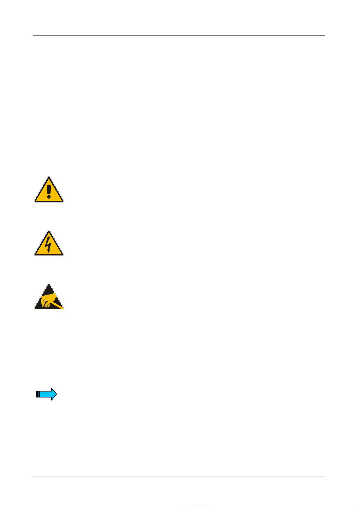
Caution!
Dangerous electrical voltage!
Before commencing the installation
● Disconnect the power supply of the device.
● Ensure that the device cannot be
accidentally restarted.
● Verify isolation from the supply.
● Earth and short circuit.
● Cover or enclose neighbouring units
that are live.
● Follow the engineering instructions (AWA)
ofthe device concerned.
● Only suitably qualified personnel may work
on this device/system.
● Before installation and before touching
thedevice ensure that you are free of
electrostatic charge.
● Connecting cables and signal lines should
be installed so that inductive or capacitive
interference do not impair the automation
functions.
● Install automation devices and related
operating elements in such a way that they
are well protected against unintentional
operation.
● Suitable safety hardware and software
measures should be implemented for the
I/Ointerface so that a line or wire breakage
on the signal side does not result in
undefined states in the automation devices.
● Ensure a reliable electrical isolation of the
low voltage for the 24 volt supply. Only use
power supply units complying with
IEC60364-4-41 or HD 384.4.41 S2.
● Deviations of the mains voltage from the
rated value must not exceed the tolerance
limits given in the specifications, otherwise
this may cause malfunction and dangerous
operation.
● Emergency stop devices complying with
IEC/EN 60 204-1 must be effective in all
operating modes of the automation devices.
Unlatching the emergency-stop devices
must not cause uncontrolled operation
orrestart.
● Devices that are designed for mounting in
housings or control cabinets must only be
operated and controlled after they have been
installed with the housing closed. Desktop
orportable units must only be operated and
controlled in enclosed housings.
● Measures should be taken to ensure the
proper restart of programs interrupted after
avoltage dip or failure. This should not
cause dangerous operating states even for
ashort time. If necessary, emergency-stop
devices should be implemented.
All brand and product names are trademarks or
registered trademarks of the owner concerned.
All rights reserved, including those of the translation.
No part of this manual may be reproduced in any form
(printed, photocopy, microfilm or any otherprocess) or
processed, duplicated or distributed by means of
electronic systems without written permission of
Moeller GmbH, Bonn.
Subject to alterations without notice.
Page 3

Contents
Part 1 Device Description Page 1-1 to 1-26
MV4-150-TA1
MV4-450-TA1
MV4-170-TA1
MV4-470-TA1
Part 2 Device Description Page 2-1 to 2-21
MV4-570-TA1/2
MV4-590-TA1/2
Part 3 Device Description Page 3-1 to 3-29
MV4-670-TA1/2
MV4-690-TA1/2
Part 4 Communications Card Description Page 4-1 to 4-55
ZB4-601-IF1
ZB4-609-IF1
Part 5 Communications Card Description Page 5-1 to 5-15
ZB4-604-IF1
PROFIBUS-DP
Part 6 Communications Card Description Page 6-1 to 6-12
ZB4-606-IF1
DeviceNet
Moeller 07/01 AWB-C2700-1347GB
Page 4

Device Description MV4-150-TA1, MV4-450-TA1, MV4-170-TA1, MV4-470-TA1 1-1
Part 1
Touch Operator Panel
Device Description
MV4-150-TA1
MV4-450-TA1
MV4-170-TA1
MV4-470-TA1
Moeller 07/01 AWB-C2700-1347GB
Page 5

Device Description MV4-150-TA1, MV4-450-TA1, MV4-170-TA1, MV4-470-TA1 1-2
Proper use
The device must only be used for the applications described in this device description and only in conjunction
with the components recommended by Moeller.
Warning !
For the trouble-free and reliable operation of this product proper transport, storage,
assembly and mounting, as well as careful operation must be ensured.
Do not switch on the device when it is covered with condensation. When changing its
location from a cold to warm area, allow the device to acclimatise to the new conditions
before commissioning.
No warranty claims will be accepted for faults arising from the improper handling of the
device.
The device should not be used for the implementation of any safety functions relating to
the protection of personnel and machinery.
No liability is accepted for claims for damages arising from a failure or functional defect
in the device.
All data specified in this document does not represent legally binding guaranteed
specifications.
Safety instructions for the user
This device description contains the information required for the proper use of the
products described therein. Sections 1 to 12 are aimed at technically qualified persons
and sections 13 to 19 at persons requiring no specific technical qualification.
Qualified persons in relation to the safety instructions in this device description or the
product itself are persons who:
are either design personnel familar with the safety concepts of automation,
or are operating personnel who are instructed in the handling of automation systems
and have a good knowledge of the contents of this device description relating to
operation,
or are commissioning and service personnel that have been properly trained and
authorised in the repair of such automation devices, and to commission circuit
components or systems in accordance with the relevant safety standards.
Moeller 07/01 AWB-C2700-1347GB
Page 6

Device Description MV4-150-TA1, MV4-450-TA1, MV4-170-TA1, MV4-470-TA1 1-3
CONTENTS
1 Explanation of symbols............................................................................................................................ 1-4
2 Introduction.............................................................................................................................................. 1-5
3 Device Versions....................................................................................................................................... 1-5
3.1 Scope of Delivery.............................................................................................................................1-6
4 Device mounting...................................................................................................................................... 1-7
4.1 General mounting instructions ......................................................................................................... 1-7
4.2 Dimensions of the 5.7″ devices MV4-150-TA1(-xx 1) , MV4-450-TA1(-xx1).....................................1-8
4.3 Front panel cutouts for 5.7″ devices ................................................................................................ 1-9
4.4 Dimensions of the 10,4″ devices MV4-170-TA1(-xx1), MV4-470-TA1(-xx1)................................ 1-10
4.5 Front panel cutouts for 10,4″ devices ............................................................................................ 1-10
5 Mounting instructions............................................................................................................................. 1-12
5.1 Mounting according to degree of protection IP 65 ......................................................................... 1-12
6 Connecting the system power supply.................................................................................................... 1-14
7 Connection to the communication interface.......................................................................................... 1-15
7.1 Preparing the connection cable (EMC).......................................................................................... 1-15
7.2 Preparing the shield connections................................................................................................... 1-16
8 Connection and function of the programming port (PROG PORT)....................................................... 1-17
9 Data transfer (Download Button)........................................................................................................... 1-18
9.1 Loading the runtime (GRSW)......................................................................................................... 1-18
9.2 Loading the project data (Download)............................................................................................. 1-19
10 Communications Cards and COM SLOT .......................................................................................... 1-20
11 Expansion and configuration options................................................................................................. 1-21
11.1 Additional 5 V power supply on programming port (PROG PORT)............................................... 1-21
12 Function and control LEDs ................................................................................................................ 1-21
13 Touch Screen..................................................................................................................................... 1-22
13.1 Basic Touch Screen function ......................................................................................................... 1-22
13.2 Power up function test.................................................................................................................... 1-22
13.3 Cleaning and maintenance of the Touch Screen........................................................................... 1-22
14 Display ............................................................................................................................................... 1-23
15 Maintenance and repair..................................................................................................................... 1-23
16 Disposal ............................................................................................................................................. 1-23
17 Technical Data................................................................................................................................... 1-24
18 EC Conformity.................................................................................................................................... 1-26
19 UL Listing........................................................................................................................................... 1-26
Moeller 07/01 AWB-C2700-1347GB
Page 7
Device Description MV4-150-TA1, MV4-450-TA1, MV4-170-TA1, MV4-470-TA1 1-4
1 Explanation of symbols
Danger warnings
The following warni ngs are provided t o ensure your personal safet y and to protect the produc t described or
connected devices from damage.
Safety instructions and warnings for the prevention of danger to the life and health of users or service
personnel, as well as the prevent ion of dam age to propert y are highli ghted througho ut this docum ent by t he
following symbols. This document always shows the different pictogrammes here for “Warnings” and “Notes”.
Warnings generally mean the following:
Indicates that death, s erious injur y or damage to propert y may occur if the r elevant pr ecautionar y measures
are not observed.
The individual Warning pictogrammes have the following meaning:
Caution ! General !
This type of warning must be observed in order to prevent hazards during the operation
of the device and at other times. Observe the correct procedure.
Danger ! Electric shock !
Voltages may occur in electrical installations that may be dangerous to persons. The
touching of live parts may cause electric shock.
Caution! Observe proper ESD protection measures !
Electrostatic discharge may destroy some components.
Notes generally mean the following:
This indicates important inf ormation on the prod uct or section of the op erating instructions t o which special
attention should be given.
The Note pictogramme has the following meaning:
Indicates important instructional information.
Moeller 07/01 AWB-C2700-1347GB
Page 8
Device Description MV4-150-TA1, MV4-450-TA1, MV4-170-TA1, MV4-470-TA1 1-5
2 Introduction
The Touch Operator Panel MV4 are visualisation units that are provided with touch zone functions for
medium to high complexity automation systems. They meet all the requirements placed on a modern
visualisation unit.
The Touch Operator Panel must be loaded with the necessary project data before it can be used. The project
data is created and loaded usin g a PC and the MV4-CFG-1 conf igurator sof tware (Ga lileo). This sof tware is
described in a separ ate documentation. The dat a transfer between the PC and the Touch Operator Panel
(Download) is implemented via a serial interface. The project data is then stored inside the device in a
retentive memory.
The Touch Operator Panel are provided with a slot for the communications card (see Section 10) which
manages the comm unication with the au tomation device. T he com munic ations cards are describe d in part 4
and 5.
This device description should be used as a reference for the installation, connections, technical data,
commissioning, operati on and maintenanc e of the units M V4-150-TA1(- xx1), MV4-450-T A1(-xx1), M V4-170TA1(-xx1), MV4-470-T A1(-xx1). The illustrati ons in this document are f or the 10.4″ version (see Sec tion 3)
unless stated otherwise. The desig nation and function of the term inals and signals are th e same, however,
for all versions.
3 Device Versions
Type designation Display size Display technology Resolution Power
supply
MV4-150-TA1(-xx1)
MV4-450-TA1(-xx1)
MV4-170-TA1(-xx1)
MV4-470-TA1(-xx1)
Units with the extention –xx1 are equipped with an acid-proof stainless steel front. These devices are
installed from the rear using threaded bolts.
5.7″ (145 mm)
5.7″ (145 mm)
10.4″ (264 mm)
10.4″ (264 mm)
LCD passive monochrome (STN)
LCD passive color (STN)
LCD passive monochrome (STN)
LCD passive color (STN)
VGA (320 x 240)
¼ VGA (320 x 240)
VGA (640 x 480)
VGA (640 x 480)
24 V DC
24 V DC
24 V DC
24 V DC
Moeller 07/01 AWB-C2700-1347GB
Page 9
Device Description MV4-150-TA1, MV4-450-TA1, MV4-170-TA1, MV4-470-TA1 1-6
3.1 Scope of Delivery
Device version
MV4 with aluminium front
MV4 with stainless steel front
Accessories:
Fixing screws for unit installation (4 off,
countersunk)
Conter frame
Seal for mounting the unit
Device and blind plate with knurled screw
for COM slot
Nuts and washers
10 x M4 with 5.7“ units; 16 x M5 with 10.4”
units
Power supply plug connector (3-pole plugin screw terminal, Phoenix Contact, Type:
MSTB 2.5/3-ST-5.08)
AWA
MV4-150-TA1
MV4-450-TA1
MV4-170-TA1
MV4-470-TA1
MV4-150-TA1-xx1
MV4-450-TA1-xx1
MV4-170-TA1-xx1
MV4-470-TA1-xx1
•
•
• •
• •
•
• •
• •
Moeller 07/01 AWB-C2700-1347GB
Page 10

Device Description MV4-150-TA1, MV4-450-TA1, MV4-170-TA1, MV4-470-TA1 1-7
4 Device mounting
4.1 General mounting instructions
The Touch Operator Panels are suitable for insta llation in an enclosur e which is closed from the rear. The
unit is installed directl y from the fr ont with four counter sunk sc rews (standar d v ersion), or f rom the rear us ing
threaded bolts and nuts (stainless steel version).
After mounting the rear of the units must be accessible (Download button, see Section 9).
The mounting version allows protection in compliance with IP 65 (see Section 5.1).
The Touch Operator Panel can be operated at a n ambient tem perature of up to 50 °C ( see Secti on 17). T he
ambient temperature r efers to the ar ea d irectl y in t he vic init y of the l ower c ool ing slits of a ver tic all y m ounted
device provided with unhind ered air convection and m ounted at a locati on no more than 2000 m above sea
level. The cooling slits must always be kept clear to ensure the proper cooling of the system.
Mounting inside an enclosur e is possible provided that the perm issible ambient temperature is observed. A
clearance of at least 30 mm from all sides of the enc los ure m ust be obs erve d in or der to e nsur e suff icient a ir
circulation.
Avoid exposing the f lat screen to direct sunlight. T he radiation from the sun (UV component) redu ces the
lifespan of the LCD display.
The cooling slits must be kept clear to ensure the proper cooling of the system.
Avoid exposing the flat screen to direct sunlight.
After mounting the rear of the device must be accessible (Download button).
Moeller 07/01 AWB-C2700-1347GB
Page 11

Device Description MV4-150-TA1, MV4-450-TA1, MV4-170-TA1, MV4-470-TA1 1-8
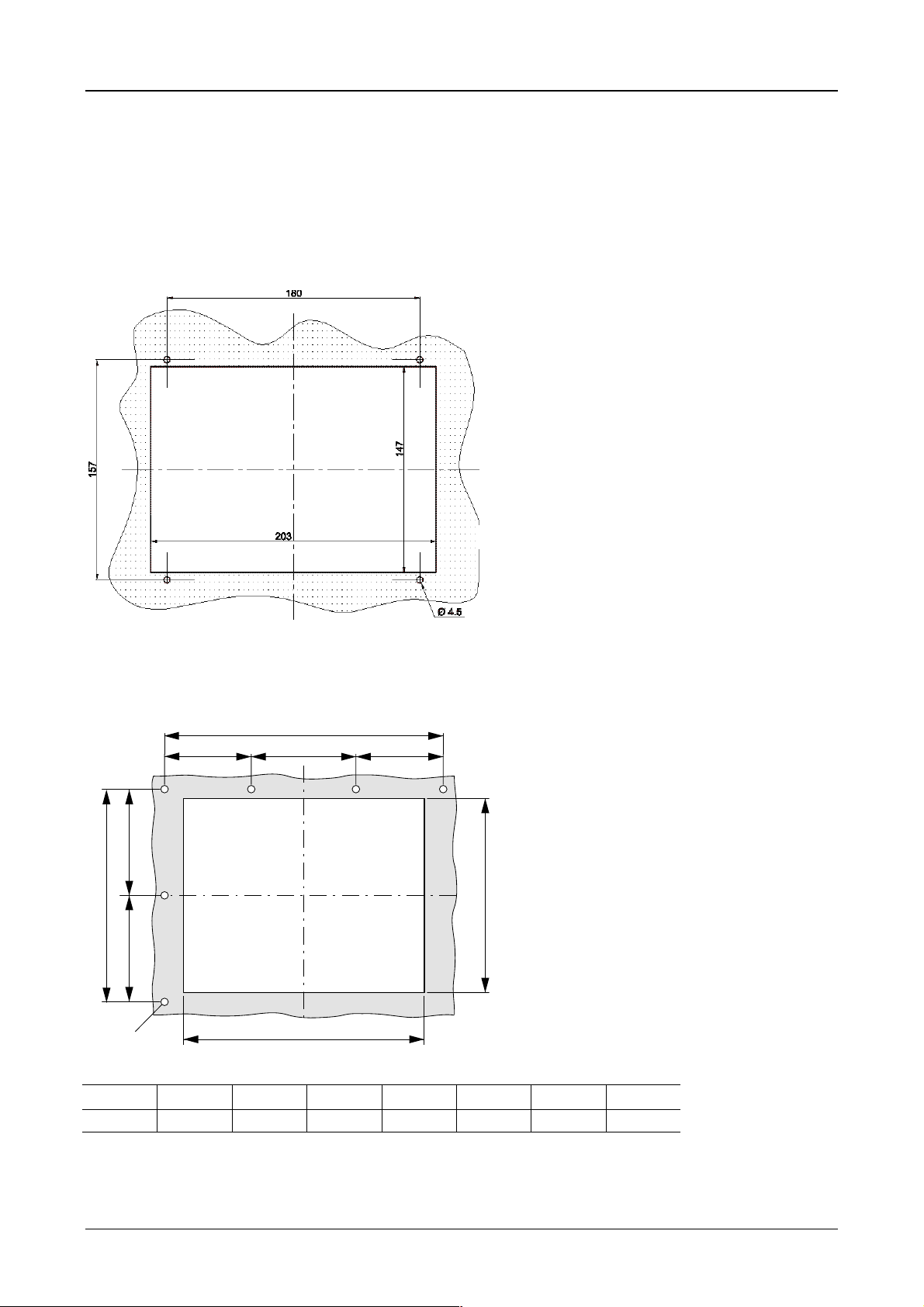
4.2 Dimensions of the 5.7″″″″ units MV4-150-TA1(-xx1), MV4-450-TA1(-xx1)
Note:
The standard unit with front hole mountin g is shown in this illustr ation. The dim ensions of the 5.7“ st ainless
steel units are ide ntical. Only the front panel cutout is different as a resu lt of the intended rear installation
with threaded bolts (refer to the following section).
Moeller 07/01 AWB-C2700-1347GB
Page 12
Device Description MV4-150-TA1, MV4-450-TA1, MV4-170-TA1, MV4-470-TA1 1-9
4.3 Front panel cutouts for 5.7″″″″ units
a) MV4-150-TA1, MV4-450-TA1
Front panel cutout : 203 mm XXXX 147 mm (centrally to fixing holes)
Fixing screws : M4 countersunk screw (supplied with unit)
b) MV4-150-TA1-xx1, MV4-450-TA1-xx1
lmhl
n
i
n
o
g
ghi kl mn
203 mm 211 mm 161 mm 147 mm 70.5 mm 70 mm 80.5 mm 4.5 mm
k
OOOO
Moeller 07/01 AWB-C2700-1347GB
Page 13
Device Description MV4-150-TA1, MV4-450-TA1, MV4-170-TA1, MV4-470-TA1 1-10
4.4 Dimensions of the 10.4″″″″ devices MV4-170-TA1(-xx1), MV4-470-TA1(-xx1)
Note:
The standard unit with front hole mountin g is shown in this illustr ation. The dim ensions of the 5.7“ st ainless
steel units are ide ntical. Only the front panel cutout is different as a resu lt of the intended rear installation
with threaded bolts (refer to the following section).
Moeller 07/01 AWB-C2700-1347GB
Page 14
Device Description MV4-150-TA1, MV4-450-TA1, MV4-170-TA1, MV4-470-TA1 1-11
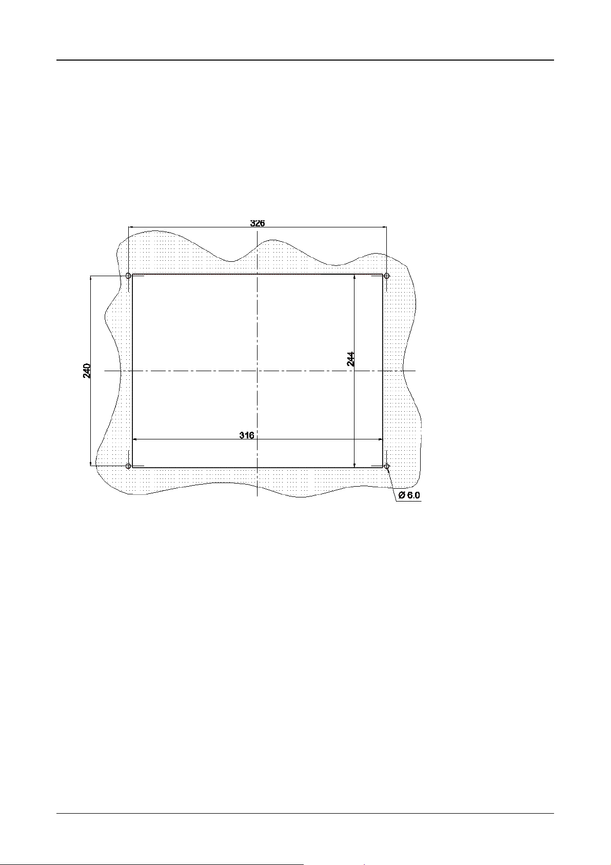
4.5 Front panel cutouts for 10.4″″″″ devices
a) MV4-170-TA1, MV4-470-TA1
Front panel cutout : 316 mm XXXX 244 mm (centrally to fixing holes)
Fixing screws : M5 countersunk screw (supplied with unit)
b) MV4-170-TA1-xx1, MV4-470-TA1-xx1
h
qqrr
p
i
po
o
g
ghi kopqr
316 mm 328 mm 256 mm 244 mm 86 mm 85 mm 66 mm 65 mm 6 mm
q
k
OOOO
Moeller 07/01 AWB-C2700-1347GB
Page 15

Device Description MV4-150-TA1, MV4-450-TA1, MV4-170-TA1, MV4-470-TA1 1-12
5 Mounting instructions
5.1 Mounting according to degree of protection IP 65
a) Installation of the unit with 4-hole aluminium front
For installation re quiring IP 65 com pliance the sup plied conter fr ame and seal m ust be used. These ens ure
that the necessary pressure is applied to the seal when mounting the unit in thin-walled front panels .
Special care should be taken during mounting to ensure correct sealing to IP 65.
1. Fit the front seal from the rear of the device.
2. Insert the unit into the panel cutout from the front (without any force).
3. The front seal must fit evenly between the front plate and the front panel.
4. Fit the conter frame from the rear of the device.
5. Tighten the countersunk screws on the device through the front panel onto the conter frame.
The countersunk screws must be tightened uniformly and securely.
6. Ensure the correct positioning and even pressure of the front seal.
Observe the general mounting instructions (see Section 4).
IP 65 can only be guaranteed with correct mounting.
Moeller 07/01 AWB-C2700-1347GB
Page 16
Device Description MV4-150-TA1, MV4-450-TA1, MV4-170-TA1, MV4-470-TA1 1-13
b) Installation of the units with a stainless steel front
Special care should be taken during mounting to ensure correct sealing to IP 65.
1. Slide the front seal from the rear over the unit cover onto the fixing bolts.
2. Place the device from the front into the housing cutout.
3. The front seal must be make flat and uniform contact between the front plate and front cover.
4. The nuts must be uniformly and securely tightened.
5. Ensure correct positioning and application of even pressure of the front seal.
Pay close attention to the mounting instructions (→ Section 4).
Moeller 07/01 AWB-C2700-1347GB
Page 17
Device Description MV4-150-TA1, MV4-450-TA1, MV4-170-TA1, MV4-470-TA1 1-14
6 Connecting the system power supply
The Touch Operator Panel is classified to protection class 3. The system power supply must be connected to
an SELV (safety extr a-low voltage) 24 V DC su pply (see Sec tion 17). T he power supp ly is not isolated. T he
0 V terminal is located directly on the housing potential. The power supply must be fuse protected
(2.5 A slow), (see Section 17). This can be accessed without having to open the device. The unit is protected
against reverse polarity, and the operation of the unit depends on correct polarity.
Observe the relevant regulations for the connection of the units.
Carry out the connection as follows:
– The cross-section of the supply cable must be between 0.75 mm² and 2.5 mm² .
– A lead or wire can be used for the connection.
– The power supply must be provided with the correct current rating (see Section 17), selectivity and
breaking capacity in accordance with the specified disconnection characteristics (see Section 17).
– A functional ground is no t compulsory for correc t operati o n. The GND is connected dir ectly to the housing
potential.
The connector (socket strip with screw terminals) is supplied with the device.
Connector assignment:
Designation Function
+24 V +24 V Power supply
GND Functional ground
0 V 0 V Power supply
+24 V GND 0 V
(Plug-in screw terminal: Phoenix Contact MSTB 2.5/3-ST-5.08)
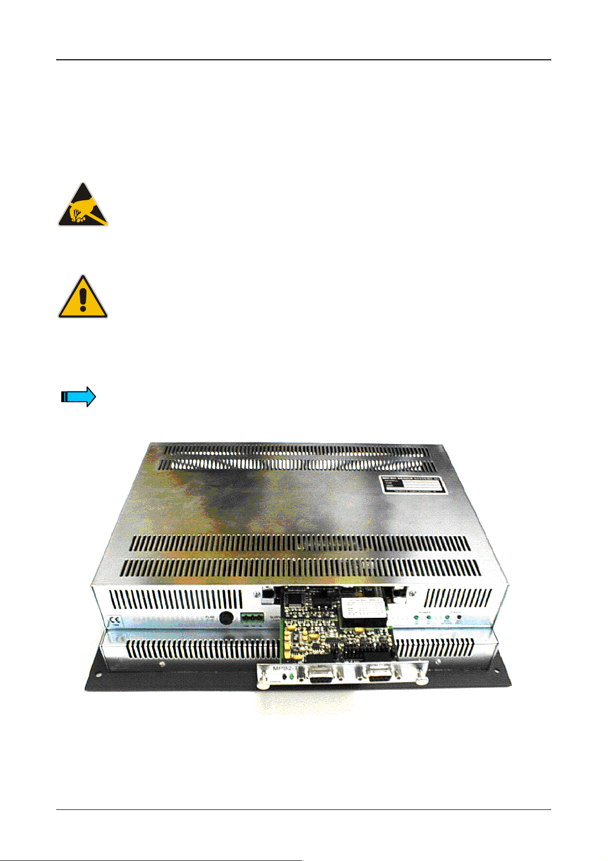
ZB4-601-IF
III
GND
Section of the connector panel with a view of the system
power supply plug connector and the fuse.
Moeller 07/01 AWB-C2700-1347GB
Page 18

Device Description MV4-150-TA1, MV4-450-TA1, MV4-170-TA1, MV4-470-TA1 1-15
7 Connection to the communication interface
7.1 Preparing the connection cable (EMC)
The preparation of the data and signal cables is an important factor for the electromagnetic compatibility
(EMC) of the Touch Operator Panel, both in terms of interference immunity and emission.
All data cables on the Touch Operator Panel (PROG PORT ) and on the card in the slot (COM SLOT ) must
be shielded unless unshielded wiring is specified explicitly. Cables connected to the communications
interface must be laid s eparately to low-voltage cabl es when they come together (cable ducts in separate
partitions).
The cable shield must be made from copper braid. Only use a metal or metallised connector casing. Connect
the cable shield directly to the low-impedance connector casing on the unit. This ensures that the cable
shield is properl y connected to the housin g of the Touch Operat or Panel via the screws and t he protective
metal shroud of the plug connector (low-impedance).
The cables must also be shi eld ed if they are not co nnecte d at the other end and are onl y used , f or exam ple,
for commissioning and servicing.
Refer to the operating instruc tions of the devic e m anuf acturers concer ned as t o how to co nnect the s hie ld at
the other end. If no specifications are given, connect the cable shield also at this end to the metal or
metallised connector casing.
Avoid leaving the shield open. The data connec tio ns to b e s h iel de d i nvol ve t he hig h- s pee d trans f er of s igna ls
between two active systems . The cable shield onl y functions against as ymmetrical interf erence transients if
the shield is connected to the device earths (usually metallic device enclosure) at both ends.
Provide a potential eq ualis ation co nd uctor with a su itabl e cros s-s ection b etween poten tials ( contro l ca binets )
if the Touch Operat or Panel and the com munications partn er are installed in different contro l cabinets or at
different PE potent ials ( zero cond uctor po tentia ls) , and if the c able s hield at bot h ends is d irectl y or in direc tl y
connected to the protect ive e arth con ductor. This wil l prevent th e occ urrenc e of large com pens ation curr ents
on the shield and shield connections. T hese k inds of com pensation c urren ts of norm ally 50 H z eve n occur in
normal operation and do not represent a problem for data transmission. However, they may cause the
destruction of the shield terminals and contacts, particularly in the event of short-circuits in the environment.
Special care should be taken with the connection to ensure interference-free operation.
The EMC values stated in the technical data can only be guaranteed if the cables are
manufactured according to the specifications.
Moeller 07/01 AWB-C2700-1347GB
Page 19
Device Description MV4-150-TA1, MV4-450-TA1, MV4-170-TA1, MV4-470-TA1 1-16
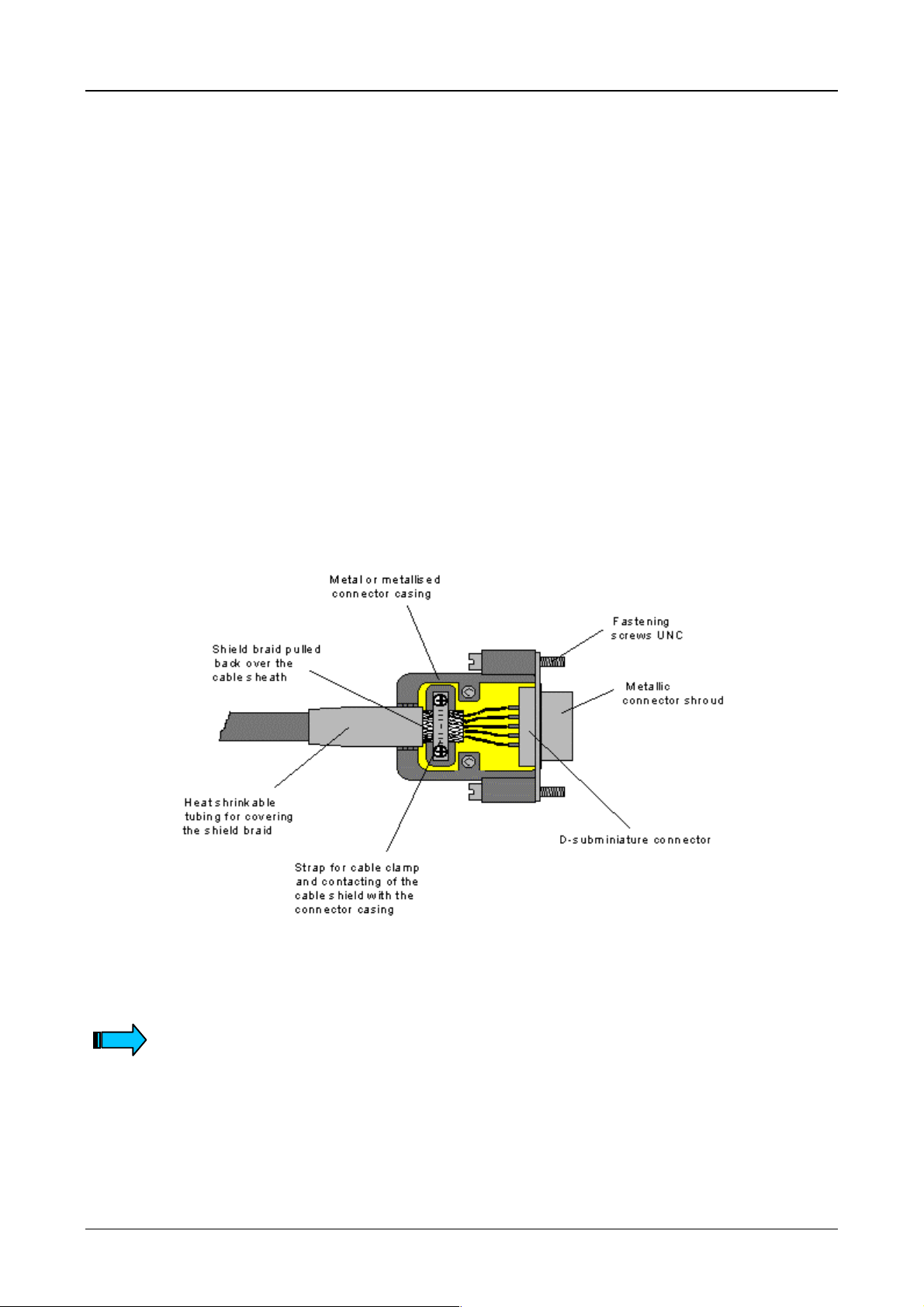
7.2 Preparing the shield connections
The connections on the Touch Operator Panel and especially the communications card are mostly
implemented with D-subm iniature connectors in accordanc e with DIN 41 652. Only us e metal or metallised
connector casings with a cab le clamp for strain relief f astened or c lamped o n o ne s ide of the con nector. T he
clamping of the cabl e shield ensures an optimum c ontact area and a low impedance c onnection with the
connector casing of the Touch Operator Panel.
The following procedure is recommended for making the low-impedance connection for the cable shield:
1. Strip the cable.
2. Shorten the exposed shield braid by approx. 3 cm.
3. Turn back the braid over the cable sheath.
4. Use a heat shrinkable t ubing or rubber grom met to cover the ex posed cable sheath with the f olded
back shield braid so that 5 to 8 mm of exposed c able shield is lef t at the sheath end an d is cleanly
covered at the back.
5. Fit the connector.
6. The cable is then fastened at the exposed shield braid and the cable sheath below it directly
underneath the cable clamp strap of the connector casing.
If plug connectors are used for communications cards (not D-subminiature plug
connectors to DIN 41 652), then follow the instructions in the relevant document
descriptions.
Moeller 07/01 AWB-C2700-1347GB
Page 20
Device Description MV4-150-TA1, MV4-450-TA1, MV4-170-TA1, MV4-470-TA1 1-17
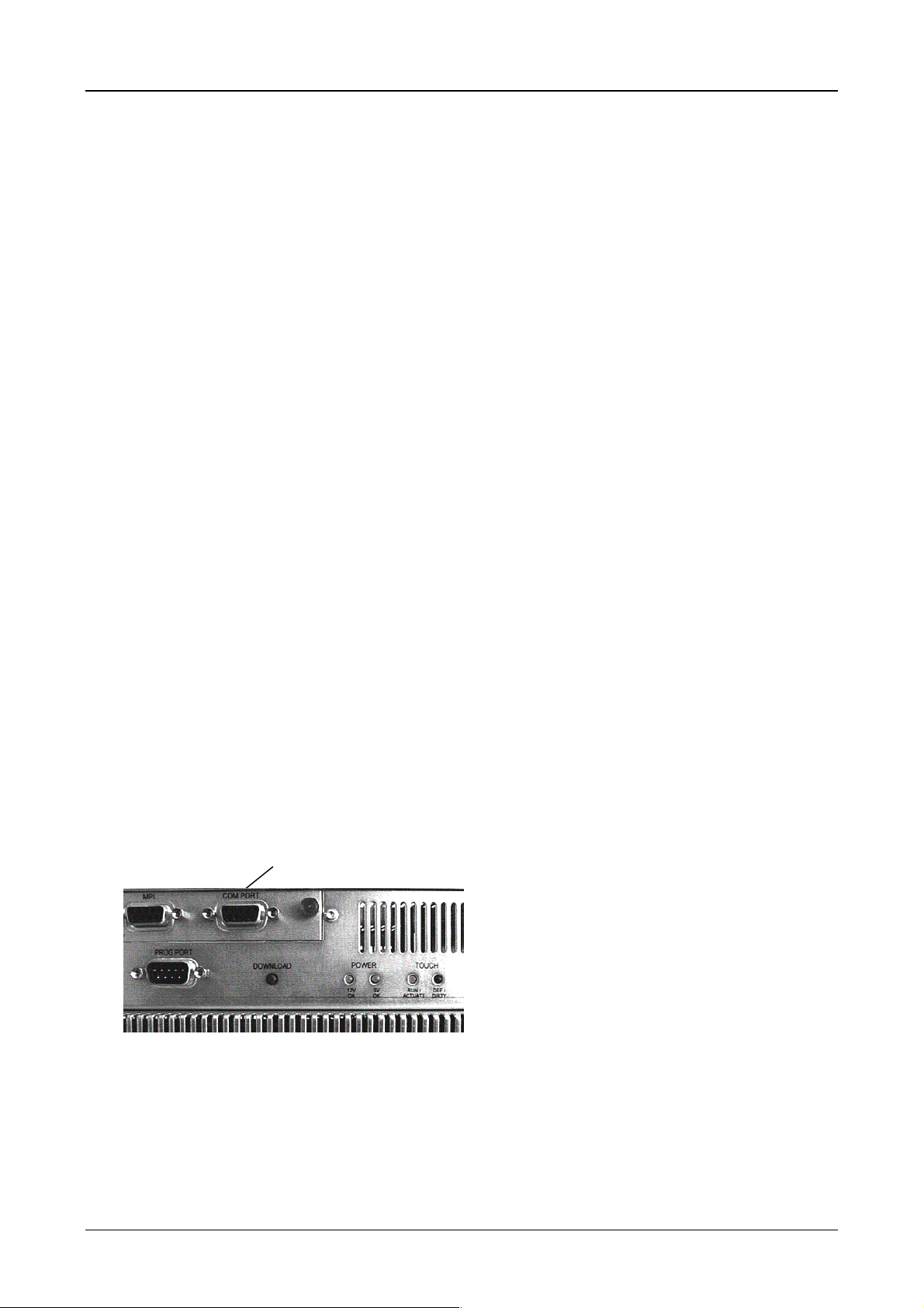
8 Connection and function of the programming port (PROG PORT)
The project data is loaded into the Touch Operator Panel (Download) via the programming port (PROG
PORT). The programming port can also be used to connect a serial printer for printing reports from the
application or for the communication via SUCOM-A protocol (from MV4-Configurator MV4-CFG-1, V 3.03).
Refer to the documentation of the MV4-configurator design software for information on
the connection and operation of a printer (printer installation).
For SUCOM-A communication select the PLC type “Moeller...PRG (COM)” in the MV4-configurator. The
required SUCOM-A cables ZB4-237-KB1 (for PS4) and ZB4-233-KB1 (for PS416) must be used with an
adapter (9-pol. SUB-D fem ale connector to 9-pol. SU B-D female c onnector). This c an be ordered un der the
designation LT307.512.1 .
The programming port is a standard RS 232 interface.
The GND terminal is located directly on the housing potential (see Section 17). Cables connected to the
PROG PORT must be laid separately to low-voltage cables.
Pin 9 can be provided with an optional +5 V (see Section 11).
PROG PORT
D-Sub 9 Pol male
Pin-No. Assignment Function
1 – Not assigned
2 RxD Receive data
3 TxD Send data
4 DTR Data terminal ready
5 GND Ground
6 DSR Ready for operation
7 – Not assigned
8 – Not assigned
9 (+5 V) +5 V Power supply (see Section 11)
Case Shield Cable shield
Moeller 07/01 AWB-C2700-1347GB
Page 21
Device Description MV4-150-TA1, MV4-450-TA1, MV4-170-TA1, MV4-470-TA1 1-18
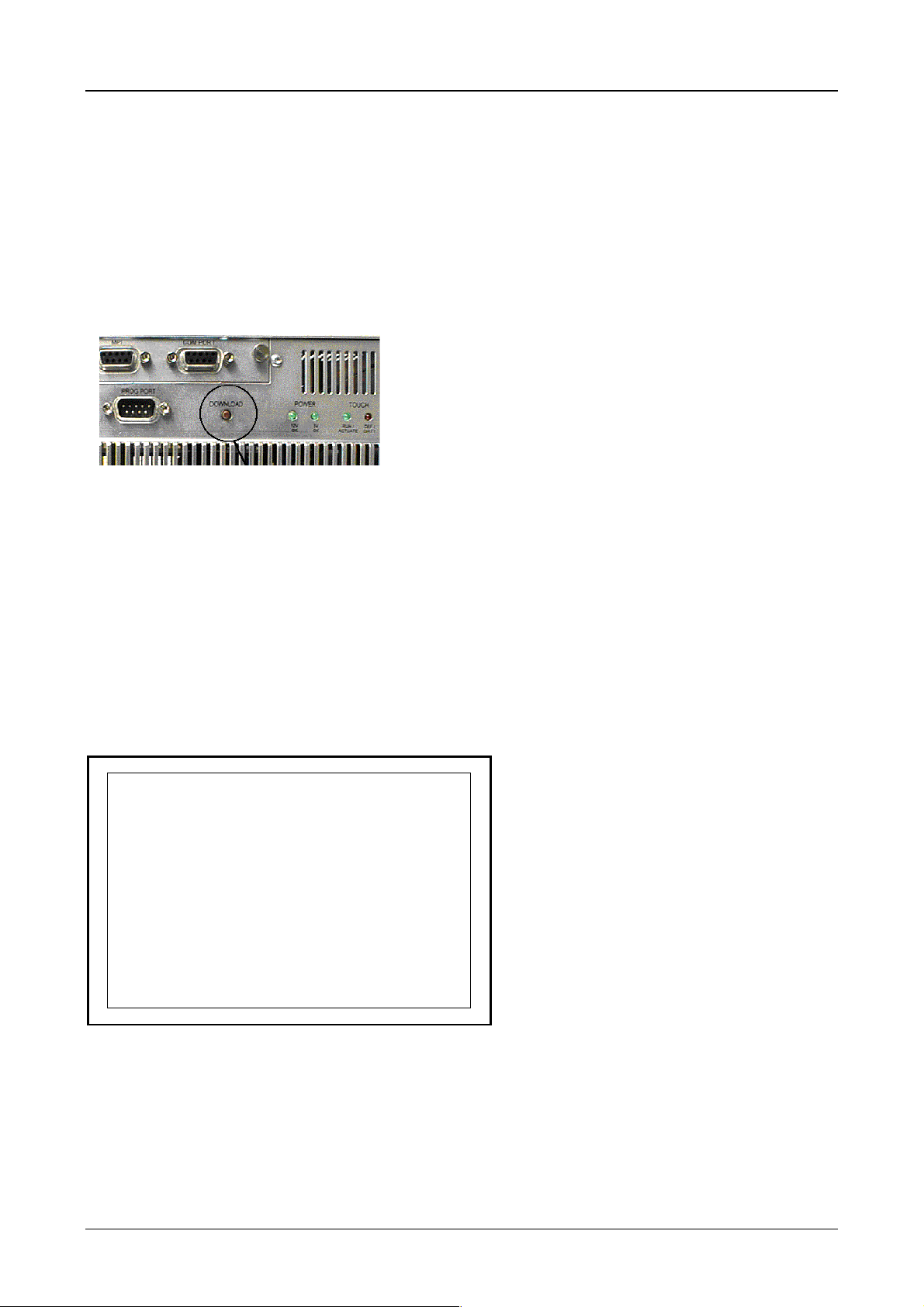
9 Data transfer (Download Button)
The Touch Operator Panel basic function is used to load the runtime program. This runtime program
(GRSW) contains the function for loading project data, and so this program must be loaded before the
loading of project data is possible.
Pressing the Download button ca lls up the functions for loading project data and/or the R untim e (Download)
(see Section 9.1 / 9.2).
The Download button is located on the rear of the Touch Operator Panel:
9.1 Loading the runtime (GRSW)
The “APPLICATION LOADER”. system mask will appear when the s ystem is started. This applicatio n loader
is a fixed part of the firmware (basic function). When the system is started the application loader searches for
the runtime. T his is ind ic ated by the system m ess age “ search program...”. The message “ok” will ap pear
when the runtime program is found.
The integrity of the runtime program is then checked, and is indicated by the system message “check
GRSW.EXE” with date and tim e. If the runtime pr ogram is corr ect, the “ok” system m essage will appear and
the runtime program is started.
MAINBOARD FIRMWARE VERSION 3.XX (WIN32)
> APPLICATION LOADER <
----------------------------------------
- search program .. ok
- check GRSW.EXE
XX/XX/XX XX:XX .. ok
System mask “APPLICATION LOADER”
Moeller 07/01 AWB-C2700-1347GB
Page 22
Device Description MV4-150-TA1, MV4-450-TA1, MV4-170-TA1, MV4-470-TA1 1-19
If the application loader does not find an integral runtime program, the unit switches to the
“SERIAL DOWNLOAD” system mask . In this mode the Touch Operator Panel will try to establish a c o nn ec tio n
to the PC via the programming port (PROG PORT). The runtime program can then be processed in
conjunction with the MV4-conf igur at or.
This mode can also be accessed by pressing the Download button. For this, press the Download button
while the Application Load er is searching for th e runtime program, i. e. whilst “search program...” is
showing in the “APPLICATION LOADER” system mask, and before the “ok” system message is shown.
The runtime program (a runtime program is already prese nt on the Touch Operator Pane l) can be updated
with the design software at any time when loading pr oj ect dat a (see Section 9.2).
MAINBOARD FIRMWARE VERSION 3.XX (WIN32)
> SERIAL DOWNLOAD <
----------------------------------------
- waiting for host ..
System mask for loading the runtime (GRSW)
9.2 Loading the project data (Download)
Pressing the Download button whilst the application is running accesses the system function for loading
project data and for reloading the runtime program. A short press of the Download button switches the
Touch Operator Panel to the “Serial Data Transfer PC<>Panel” system mask.
In this Download mode the Touch Operator Panel tries to establish a connection to the PC via the
programming port (PROG PORT). The MV4-configurator can then be used to load project data and/or to
reload the runtime program.
Error: <DOWNLOAD> button pressed...
Serial Data Transfer PC <> Panel
Waiting for serial download...
Press <DOWNLOAD> button to reboot
System mask for serial data transfer
The system also s witches to this Do wnload mode if the runtim e program does not find an exec utable pr oject
or in the event of a f atal er ror. T he s ystem indicat es the re ason f or the c hange t o Down load mode in the first
line of the screen.
To quit Download mode press the Download button or briefly interrupt the power supply.
Moeller 07/01 AWB-C2700-1347GB
Page 23
Device Description MV4-150-TA1, MV4-450-TA1, MV4-170-TA1, MV4-470-TA1 1-20
10 Communications Cards and COM SLOT
The Touch Operator Panel has one slot for a communications card (see Section 17). The link to the
automation equipment (e. g. PLC) or the fieldbus system is implemented using one of the several cards
available. Further information see part 3 and 4 of this documentation.
Safety precautions concerning electrostatic discharge (ESD) must be observed
when handling cards !
Never plug in the cards with the power supply switched on.
Only operate the communications card once it has been fully screwed into position.
Do not run any non-Moeller components in the slots.
Only original hardware from Moeller may be used.
Refer to the relevant communication card descriptions for information on protocols,
configuration, cable lengths etc.
Communications card in COM SLOT of the Touch Operator Panel
Moeller 07/01 AWB-C2700-1347GB
Page 24
Device Description MV4-150-TA1, MV4-450-TA1, MV4-170-TA1, MV4-470-TA1 1-21
11 Expansion and configuration options
11.1 Additional 5 V power supply on programming port (PROG PORT)
Pin 9 of the PROG PORT (see Sec t ion 8) c an als o be us e d f or the po wer s upp l y (+5 V) of ex tern al additional
hardware (jumper J7 on the m ain board set to position A). This is not short-circuit proof and not overload
protected and mus t only be used in conj unction with origin al Moel ler hard ware. The po wer supp ly c annot b e
used for non-Moeller products.
12 Function and control LEDs
The Touch Operator Panel provides two LEDs for monitoring the f unctions of the touch control ler (
and two other LEDs for monitor ing the system voltages (
POWER
). They are located un derneath the COM
TOUCH
SLOT.
TOUCH
DEF/DIRTY
The LED (red) is lit if dur ing the power up f unct ion tes t of th e T ouch Sc ree n th e sign al
level of one or several IR channels is below the minimum level (see Section 13.2).
A reduction of the s ignal level is caused b y the contaminati on of the IR transpar ent
plastic frame or the failure of an optical elem ent. If this LED is lit, clean the plastic
frame on the device front (see Section 13.3).
RUN/ACTUATE
The LED (green) remains unlit whe n the system voltage is s witched on. It will light u p
once the initialisation of the touch controller has been successfully completed.
The LED will be deactivated for approx. 0.3 seconds when the touch screen is
pressed.
POWER
12 V OK
5 V OK
When lit the LEDs indicate the presence of the system voltages (+12 V and +5 V).
If the LEDs are not lit when the system voltage is applied, check the fuse.
When the system voltage is switched on, both Touch LEDs are activated for approx. 0.3 seconds as a
function check.
COM SLOT
)
Section of the connector panel with a view of the control LED, the PROG PORT and the COM SLOT
Moeller 07/01 AWB-C2700-1347GB
Page 25

Device Description MV4-150-TA1, MV4-450-TA1, MV4-170-TA1, MV4-470-TA1 1-22
13 Touch Screen
13.1 Basic Touch Screen function
The Touch Screen operates on the ac tive lig ht matr ix princi ple in the infrared r ange. T he optical elem ents of
the light matrix are located behind the IR transpar ent plastic fr ame in the front pa nel of the de vice. The y are
located in such a way that their radiation extends s lightly out of the fr ont pane. Each emitter is ass igned a
receiver that is loc ated on the other side. In this way 40 closel y positioned IR channe ls are pro vided on the
5.7″ unit and 70 IR chann els on the 10.4″ unit (see Section 17). A touch on th e screen is detected by the
simultaneous interruption of one or several channels in the X or Y axis.
Repeated touches and to uches that cover an area greater than 20 mm x 20 mm are not evaluated by the
controller. Continu ously interrupted channe ls caus ed by s e ver e c ont amination and dirt, or by the failure of an
optical element are detected by the touch contr o ller and are no longer inclu ded in the eval uat ion .
13.2 Power up function test
The Touch Operator P anel carries o ut a functio n test of the to uch screen with eac h power up of the dev ice.
This test measures the signal levels of all IR channels and compares them with initial values. The initial
values are determined before the device is delivered and stored in a retentive memory.
If the signal of one or several channels is below a minimum level relative to th e initial values, this will b e
indicated by an error message on the screen and the
of this kind is nor mally due to sever e contamination of the IR transparent plas tic frame which conseque ntly
has to be cleaned (see Section 13.3). The Touch Screen, however, remains fully functional.
Only an increase in the contam ination of the sc reen will lead t o the cont inuous interrupti on of one or se veral
IR channels. IR channels that are continuousl y interrupted will be detect ed by the Touch Contro ller and no
longer included in the evaluation . In ex trem e cas es, this m ay mean that i ndiv idual zo nes c annot be ac tivated
by touch.
Do not touch the screen whilst the system is being started up, and wait tillyour
application has started.
During the startup the Touch Screen carries out a function test in which the signal
levels of the IR channels are measured.
DEF/DIRTY
LED (see Section 12). A r ed uc ed s i gna l le vel
13.3 Cleaning and maintenance of the Touch Screen
For operation ensure that the s ignal lev els of th e channe ls are not s o severe ly redu ced or int errupted d ue to
excessive contamination through dirt (see Section 13.1).
Clean the inside of the plastic f rame of the dev ice regular ly (see S ection 15) with a damp soft c loth. Ensure
that the surface is not scratched or scoured, especially when removing hard deposits and abrasive dust.
Do not expose the front of the device to solvents which m ay corrode and destroy the p lastic frame (frame
material: polymethylmethacrylate, PMMA).
Moeller 07/01 AWB-C2700-1347GB
Page 26

Device Description MV4-150-TA1, MV4-450-TA1, MV4-170-TA1, MV4-470-TA1 1-23
14 Display
The different vers ions of the T ouch Oper ator Pan el are avail able with dif fer ent d ispla y t echno logies . Pas sive
LCD, monochrome or color screens are available.
The individual pixels of an LCD displ ay are not actively illuminated. The im age is produced by illum inating
the screen by a backlight which is varied in colour and intensity by means of the individual LCD cells (pixels).
The light of this backlight is provided b y a cold cathod tu be. The lifespan of these tubes ( see Section 17) is
limited and depends on the operating conditions at hand. The brightness setting of the backlight and the
number of switch-on cycles will determine the lifespan of the screen. Reducing the brightness can
significantly increas e the lif espan of the LCD dis play. Fr equent sw itching, es pecially at low tem peratures will
reduce the lifespan.
Therefore avoid frequent switc hing on and of f of the back light or the ent ire s ystem. Reducing th e brightness
to a minimum setting is better than frequently switching the display on and off.
Particularly with LCD displays the image contr ast depends on the view ing angle. T he operating t emperature
also has a direct influence on the contrast and consequently also on the viewing angle. Any detrimental
influences caused b y temperature are reduc ed by an additiona l circuit in the device (part ial compensation) .
The contrast (contras t voltage) ma y need to be adjusted due to the viewing angle requ irements of different
people or changes in the ambient temperature. This can be carried out on the Touch Panel by the operator.
Further information on adjusting the brightness of the backlight and the contrast is provided in the
documentation of the MV4-configurator.
15 Maintenance and repair
The Touch Operator Panels are maintenance-free.
The inside of the device front panel should be cleaned regularly to ensure trouble-free IR touch screen
operation (see Section 13.3).
Repairs to the units must only be carried out by the manufacturer.
Modifications made to the device that are not described in this document are not permitted and no liability will
be accepted for them.
16 Disposal
Touch Operator Panels that are no longer used must be disposed of properly or returned to the manufacturer
for disposal.
Special note:
– The clock module contains a sealed lithium battery.
(Real Time Clock, Dallas DS12887 or STMicroelectronics M48T86PC1)
– The backlights for units with LCD displays are provided by fluorescent tubes that contain mercury.
Moeller 07/01 AWB-C2700-1347GB
Page 27

Device Description MV4-150-TA1, MV4-450-TA1, MV4-170-TA1, MV4-470-TA1 1-24
17 Technical Data
Display
Technology MV4-450-TA1(-xx1)
MV4-470-TA1(-xx1)
MV4-150-TA1(-xx1)
MV4-170-TA1(-xx1)
Resolution
5.7″
10.4″
Display area
5.7″
10.4″
Number colours/greyscale 256
Contrast ratio (normally) MV4-450-TA1(-xx1)
MV4-150-TA1(-xx1)
MV4-470-TA1(-xx1)
MV4-170-TA1(-xx1)
Brightness (normally) MV4-450-TA1(-xx1)
MV4-150-TA1(-xx1)
MV4-470-TA1(-xx1)
MV4-170-TA1(-xx1)
Lifespan if backlight
MV4-450-TA1(-xx1) 25,000 Operating hours
(only LCD/without backlight saver) MV4-150-TA1(-xx1)
MV4-470-TA1(-xx1)
MV4-170-TA1(-xx1)
Operation
MDS TCL2
Optical light matrix in the infrared range (IR Touch, see Section 13)
Resolution physical
5.7″ device
10.4″ device
Resolution logic
5.7″ device
10.4″ device
LCD passive colour (STN)
LCD passive colour (STN)
LCD passive monochrome (STN)
LCD passive monochrome (STN)
320 x 240 pixels
640 x 480 pixels
115 x 86 mm
212 x 158 mm
2
2
25
24
30
18
110 cd/m
140 cd/m
70 cd/m
75 cd/m
2
2
2
2
20,000 Operating hours
25,000 Operating hours
25,000 Operating hours
24 x 16 (13 x 15 pixels)
40 x 30 (16 x 16 pixels)
47 x 31 (7 x 8 pixels)
79 x 59 (8 x 8 pixels)
System memory
Prog Port
Ambient conditions
Protection type
Front panel
Technology Flash
Basic unit 4 MByte (permanently soldered)
RS 232, non-isolated (see Section 8)
Operating climate 0 to 50 °C, 10 to 85 % rel. air humidity,
non-condensing (see Section 4)
Storage climate –20 to 60 °C, 10 to 85 % rel. air humidity,
non-condensing
Mech. shock IEC 60068-2-27 (1 shock, half-sinus 50 g/20 ms)
Vibration IEC 60068-2-6 (10 to 200 to 10 Hz/1.5 g)
EMC IEC/EN 61000-4-2, 6 kV/8 kV
IEC/EN 61000-4-3, 10 V/m
IEC/EN 61000-4-4, 2 kV
IEC/EN 61000-4-6, 10 V
EMF
IEC/EN 61000-4-8, 10 A/m
Radio interference CISPR 11, EN 55011, Class A
Front IP 65 (NEMA 12), to IEC/EN 60529
Rear IP 20
5.7″
10.4″
Glass 2.0 mm, non-reflective (etched)
Glass 3.0 mm, non-reflective (coated)
Weight
5.7″
10.4″
approx. 2.2 kg
approx. 3.6 kg
Moeller 07/01 AWB-C2700-1347GB
Page 28

Device Description MV4-150-TA1, MV4-450-TA1, MV4-170-TA1, MV4-470-TA1 1-25
Dimensions
System supply
Fuse protection
Front
Rear
5.7″ device
10.4″ device
5.7″ device
10.4″ device
220 x 170 mm
342 x 270 mm
201 x 144 x 83 mm
310 x 240 x 81 mm
Rated voltage SELV 24 V DC, Safety extra-low voltage (see Sec. 6)
Voltage range 24 V DC to EN 61131-2
20.4 to 28.8 V DC effective,
absolute value with ripple 18.5 to 30.5 V
35 V DC for < 100 ms
Voltage dips 5 ms max., at 20.4 V DC to 0 V DC, repetition rate 1 s
Reverse polarity protection Yes
Isolation No
0 V and PE connection to housing potential
Power consumption
(incl. comms. card)
5.7″ device
10.4″ device
Inrush current 1.5 A
Current consumption
(incl. comms. card)
5.7″ device
10.4″ device
2
s
0.7 A (normally)
0.7 A (normally)
20 W
20 W
Internal 2.5 A slow, to EN 60127-2/2
(externally accessible, see Section 6)
Maximum disconnection
35 A (see Section 6)
capacity
Interfaces
1 slot for communications card (see Section 10)
Moeller 07/01 AWB-C2700-1347GB
Page 29

Device Description MV4-150-TA1, MV4-450-TA1, MV4-170-TA1, MV4-470-TA1 1-26
18 EC Conformity
The Touch Operator P anel meets the requirem ents specified b y the EC Council Dir ectives for har monizing
the regulations of EC member states relating to electrom agnetic compatibility (89/336/EEC) a nd electrical
safety (Low-Vol tage Directive 73/23/EEC).
The generic standards below were use d to assess the electrom agnetic compatibility of the Touch Operat or
Panels:
EN 50 081-2 (Emission)
EN 50 082-2 (Immunity)
The following standard was used to assess the electrical safety of the Touch Operator Panels:
EN 60 950
1999
Manufacturer: Moeller GmbH
Hein-Moeller-Straße 7 – 11
D-53115 Bonn
Federal Republic of Germany
19 UL Listing
The Touch Operator Panel is listed by Underwriters Laboratories Incorporated (UL). File E208621.
Representative sam ples of the units have been evaluated b y Underwriters Laboratories Incorporated and
meet the applicable United States and Canadian safety standards.
To assess the safety of the Touch Operator Panel the safety standard UL 1950 (Safety of Information
Technology Equipment, Including Electrical Business Equipment) was used.
Moeller 07/01 AWB-C2700-1347GB
Page 30

Device Description MV4-570-TA1/2, MV4-590-TA1/2 2-1
Part 2
Touch Operator Panel
Device Description
MV4-570-TA1/2
MV4-590-TA1/2
Moeller 07/01 AWB-C2700-1347GB
Page 31

Device Description MV4-570-TA1/2, MV4-590-TA1/2 2-2
CAUTION !
The device should only be installed by qualified personnel,
observing the instructions given in section 12 (Installation
Instructions) of this document.
Only qualified personnel shall be allowed to repair this device.
Removing parts of the housing from this device exposes parts of the
system carrying a dangerous voltage. Only operate the de vice in its
original condition with all parts of the housing firmly fastened.
To avoid damage to the electronics do not switch on the device
when condensation is present. When changing its location from a
cold to a warm area, allow the device to adjust temperature before
commissioning.
No guarantee claims will be recognised for faults arising from the
improper handling of the device.
The device should not be used for the implementation of any safet y
functions relating to the protection of personnel and machinery.
No liability is accepted for claims fo r damages arising from a failure
or functional defect in the device.
All data specified in this document does not represent legally
binding guaranteed specifications.
Moeller 07/01 AWB-C2700-1347GB
Page 32

Device Description MV4-570-TA1/2, MV4-590-TA1/2 2-3
CONTENTS
1 Introduction.............................................................................................................................................. 2-4
2 Device version......................................................................................................................................... 2-4
3 Scope of delivery..................................................................................................................................... 2-5
4 EC Conformity .........................................................................................................................................2-6
5 Technical Data......................................................................................................................................... 2-6
6 Dimensions, Views, Front Plate Cutout................................................................................................... 2-8
6.1 General mounting instructions ......................................................................................................... 2-8
6.2 Dimensions 10.4″- unit MV4-570-TA1/2(-xx1) ................................................................................. 2-9
6.3 Front panel cutouts for 10.4″ units................................................................................................. 2-10
6.4 Dimensions for 13.8″ unit - MV4-590-TA1/2(-xx1) ......................................................................... 2-12
6.5 Front cover cutout for 13.8″ units................................................................................................... 2-13
7 Connection Assignment ........................................................................................................................ 2-14
7.1 System power supply for AC Versions (100 to 240 V AC, TA2 units) ........................................... 2-14
7.2 System power supply for DC Versions (24 V DC, TA1-units)........................................................ 2-14
7.3 System Port (Function, Assignment).............................................................................................. 2-15
8 Memory Card Slot.................................................................................................................................. 2-15
9 The Touch Screen................................................................................................................................. 2-16
9.1 Basic function of the Touch Screen ............................................................................................... 2-16
9.2 Power up function test.................................................................................................................... 2-16
9.3 Cleaning and care of the Touch Screen......................................................................................... 2-16
10 Function and control LEDs ................................................................................................................ 2-17
11 Communication Modules and System Expansion (Slot 0, Slot 1) ..................................................... 2-18
12 Installation Instructions ...................................................................................................................... 2-19
12.1 Device installation .......................................................................................................................... 2-19
12.2 Mounting to IP 65 ........................................................................................................................... 2-19
12.3 Preparation of the connection cables (EMC) ................................................................................. 2-20
12.4 Preparing the shield connections................................................................................................... 2-21
Moeller 07/01 AWB-C2700-1347GB
Page 33

Device Description MV4-570-TA1/2, MV4-590-TA1/2 2-4
1 Introduction
The MV4 Touch Oper ator Panels are visualisat ion units provided with t ouch zone functions for medium to
high complexity automation systems, meeting all the requirements placed on a modern visualisation unit.
The Touch Operator Pane ls must be loaded befor e use with the appropriat e project data. This is s tored in
the external plug-in memory card (PC car d). The memory card in the MV4 can be loade d with project data
via a download or directly on the PC (PC card slot). The project data is created using the MV4-CFG-1
configurator software (Galileo).
The Touch Operator Panels provide two slots for communication modules (see Section 11). The
communication card handles the connection to the automation system. They are described in Part 4 and 5.
This device descr iption is a ref erence for technical data, information on installing, terminals, com missioning
and operating of the MV4-570-TA1/2(-xx1) and MV4-590-TA1/2(-xx1) device versions. The illustrations in
this documentation refer to the 10.4″ Versions (see Section 2), unless otherwise noted. Lettering and
function of the terminals and indicators are the same for all device versions.
2 Device version
Type designation Display size Display techn olo gy Resolution Supply voltage
MV4-570-TA1(-xx1)
MV4-570-TA2(-xx1)
MV4-590-TA1(-xx1)
MV4-590-TA2(-xx1)
Units with the extention –xx1 are equipped with an acid-proof stainless steel front. The standard devices
have an aluminium front.
10.4″ (264 mm)
10.4″ (264 mm)
13.8″ (351 mm)
13.8″ (351 mm)
LCD active color
(TFT)
LCD active color
(TFT)
LCD active color
(TFT)
LCD active color
(TFT)
VGA (640 x 480) 24 V DC
VGA (640 x 480)
VGA (640 x 480) 24 V DC
VGA (640 x 480)
100 to 240 V AC,
50/60 Hz
100 to 240 V AC,
50/60 Hz
Moeller 07/01 AWB-C2700-1347GB
Page 34
Device Description MV4-570-TA1/2, MV4-590-TA1/2 2-5
3 Scope of delivery
Device version
MV4 with aluminium front
MV4 with stainless steel front
Accessories:
Fixing screws for device installation (4 off,
countersunk)
Conter frame
Seal for device installation
PC card retaining device
Two blind plates with knurled screws for
System Slot 1 and System Slot 2
Nuts and washers
16 x M5 with 10.4“ units; 16 x M6 with 13.8“
units
Power supply plug
– DC Version MV4-570/590-TA1(-xx1):
plug-in screw terminal (3 pole)
(Phoenix Contact, Type: MSTB 2.5/3-ST-
5.08)
– AC Version MV4-570/590-TA2(-xx1):
Standard appliance plug
AWA
MV4-570-TA1/2
MV4-590-TA1/2
MV4-570-TA1/2-xx1
MV4-590-TA1/2-xx1
•
•
• •
• •
• •
•
• •
• •
Moeller 07/01 AWB-C2700-1347GB
Page 35

Device Description MV4-570-TA1/2, MV4-590-TA1/2 2-6
4 EC Conformity
The Touch Operator Panels meet the requirements specified by the Directives of the EC Council for
harmonizing the regul ati ons of EC member states relat ing to e lec tromagnetic com patibi lity (89/336/EEC) a nd
electrical safety (Low-Voltage Directive 73/23/EEC).
The following basic standards were used to assess the electromagnetic compatibility of the units:
EN 50 081-2 (Emission)
EN 50 082-2 (Immunity)
The following standard has been used as a basis for assessing the units with respect to its electrical safety:
EN 60 950
1998
Manufacturer: Moeller Gm bH
5 Technical Data
Display
Operation
Technology
(fully graphic)
Resolution 640 x 480 pixels
Colours 256
Contrast ratio min. 100
Display area
Luminance
Lifespan of backlight
(without backlight saver)
Optical light matrix in infrared range (IR Touch)
Resolution physical
Resolution logical
LCD active colour (TFT)
10.4″
13.8″
10.4″
13.8″
10.4″
13.8″
10.4″
13.8″
10.4″
13.8″
212.2 x 158.4 mm
281.0 x 208.0 mm
250 cd/m
180 cd/m
25,000 Operating hours min.
10,000 Operating hours min.
40 x 30 (16 x 16 pixels)
46 x 34 (14 x 14 pixels)
79 x 59 (8 x 8 pixels)
91 x 67 (7 x 7 pixels)
2
2
2
2
Memory Card Slot
PC-card to JEIDA/PCMCIA Type
I
or Type
II
Technology – Flash linear, 5 V/5 V or 5 V/12 V, max. 64 MB
– ATA-Flash (from Mainboard Firmware Version 1.10)
System Port
RS 232, non-isolated (see Section 7.3)
Moeller 07/01 AWB-C2700-1347GB
Page 36

Device Description MV4-570-TA1/2, MV4-590-TA1/2 2-7
Ambient conditions
Front
Weight
Dimensions
Operation 0 to 50 °C, 10 to 90 % rel. air humidity,
non-condensing
Storage –20 to 60 °C, 10 to 90 % rel. Air humidity,
non-condensing
Mech. shock IEC 60 068-2-27 (1 shock, half sinus 50 g/20 ms)
Vibration IEC 60 068-2-6 (10 TO 200 TO 10 HZ/1.5 G)
EMC compliance IEC/EN 61 000-4-2, 6 kV/8 kV
IEC/EN 61 000-4-3, 10 V/m
IEC/EN 61 000-4-4, 2 kV
IEC/EN 61 000-4-5, 1 kV/2 kV (AC Version only)
IEC/EN 60 801-6, 10 V
EMF
IEC/EN 61 000-4-8, 10 A/m
Radio interference voltage CISPR 11, EN 55 011, Class A (AC Version only)
Emitted interference CISPR 11, EN 55 011, Class A
Degree of protection (front) IP 65 (NEMA 12), to IEC/EN 60 529
Degree of protection, rear IP 20
Glass 3.0 mm, anti-reflective
10.4″
13.8″
Front
approx. 4.8 kg
approx. 6.9 kg
10.4″ Device
13.8″ Device
342 x 270 mm
460 x 350 mm
System power AC Versions (MV4-570/590-TA2)
supply
Rated voltage
100 to 240 V AC
Voltage range 85 to 264 V AC
Rated frequency 50 to 60 Hz
Power consumption 40 W max.
Fuse 1.0 AT, externally access ible
DC Versions (MV4-570/590-TA1)
Rated voltage 24 V DC
Voltage range 24 V DC to DIN EN 61 131-2
20.4 to 28.8 V DC effective,
absolute value with ripple 18.5 to 30.5 V
Power consumption 40 W max.
Current consumption 1.0 A norm.
Fuse 4.0 AT, externally access ible
Inrush current 3.0 A
Interfaces/Slots
2 slots for communication modules (Slot 0, Slot 1)
2
s max.
Moeller 07/01 AWB-C2700-1347GB
Page 37

Device Description MV4-570-TA1/2, MV4-590-TA1/2 2-8
6 Dimensions, Views, Front Plate Cutout
6.1 General mounting instructions
The Touch Operator Panels are suitable for insta llation in an enclosur e which is closed from the rear. The
unit is installed directl y from the fr ont with four counter sunk sc rews (standar d v ersion), or f rom the rear us ing
threaded bolts and nuts (stainless steel version). For correc t installation of all var iants, the thicknes s of the
front cover must be sufficient, and the installation must be performed according to the defined installation
procedure (refer to section 12).
The installation variants enable installation according to IP 65 degree of protection (see section 12).
The Touch Operator Panel can be operated at an ambient temperature of up to 50 °C. The ambient
temperature refers to the area direct ly in the vicin ity of the lower c ooling slits of a vertica lly mounted device
provided with unhindered air convection and mounted at a location no more than 2000 m above sea leve l.
The cooling slits must always be kept clear to ensure the proper cooling of the system.
Mounting inside an enclosur e is possible provided that the perm issible ambient temperature is observed. A
clearance of at least 30 mm from all sides of the enc los ure m ust be obs erve d in or der to e nsur e suff icient a ir
circulation.
Avoid exposing the f lat screen to direct sunlight. T he radiation from the sun (UV component) re duces the
lifespan of the LCD display.
The cooling slits must be kept clear to ensure the proper cooling of the system.
Avoid exposing the flat screen to direct sunlight.
After mounting the rear of the device must be accessible (Download button).
Moeller 07/01 AWB-C2700-1347GB
Page 38

Device Description MV4-570-TA1/2, MV4-590-TA1/2 2-9
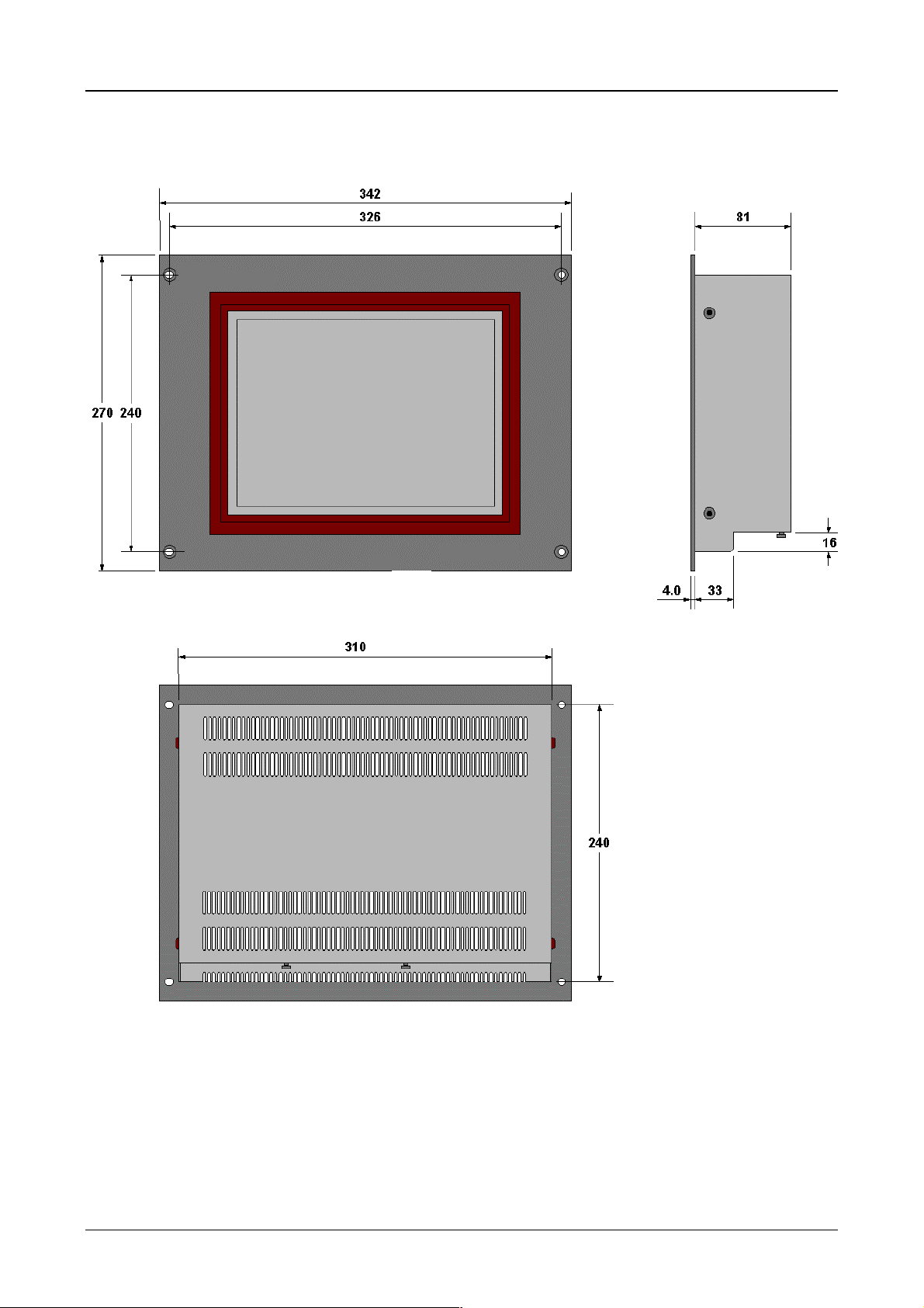
6.2 Dimensions 10.4″″″″- unit MV4-570-TA1/2(-xx1)
342
326
GF-1
240270
81
310
MICRO DESIGN
Farbe : MFS RAL 7016
16
4.0 33
240
Note:
The standard unit with front hole m ounting is s hown in th is il lustration. The dim ensions of the 10.4“ stainles s
steel units are ide ntical. Only the front panel cutout is different as a resu lt of the intended rear installation
with threaded bolts (refer to the following section).
Moeller 07/01 AWB-C2700-1347GB
Page 39
Device Description MV4-570-TA1/2, MV4-590-TA1/2 2-10
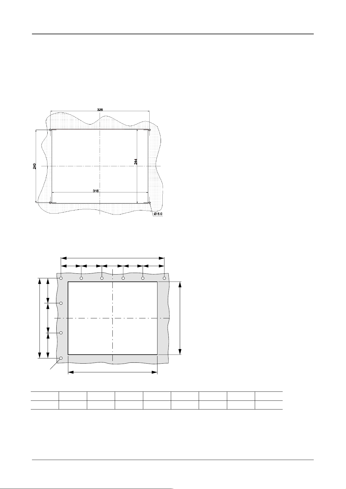
6.3 Front panel cutouts for 10.4″″″″ units
a) 10.4″″″″ units for 4-hole front mounting - MV4-570-TA1, MV4-570-TA2
Front panel cutout: 316 mm XXXX 244 mm (centrally to fixing holes)
Fixing screws : M5 countersunk screws (suppl ied wit h unit)
Moeller 07/01 AWB-C2700-1347GB
Page 40

Device Description MV4-570-TA1/2, MV4-590-TA1/2 2-11
b) 10.4″″″″ unit stainless steel version - MV4-570-TA1-xx1, MV4-570-TA2-xx1
Front panel cutout: 316x244 mm (centrally to fixing holes)
Moeller 07/01 AWB-C2700-1347GB
Page 41

Device Description MV4-570-TA1/2, MV4-590-TA1/2 2-12
460
6.4 Dimensions for 13.8″
GF-1
290350
″ unit - MV4-590-TA1/2(-xx1)
″ ″
430
MICRO DESIGN
94
50
412
4.0 38
Farbe : MFS RAL 7016
314
Note:
The standard unit with front 4-hole mounting is shown in this illustration. The dimensions of the 13.8“
stainless steel units are identical. Only the front panel cutout is different as a result of the intended rear
installation with threaded bolts (refer to the following section).
Moeller 07/01 AWB-C2700-1347GB
Page 42
Device Description MV4-570-TA1/2, MV4-590-TA1/2 2-13
6.5 Front cover cutout for 13.8″″″″ units
a) 13.8″″″″ units for 4-hole front mounting - MV4-590-TA1, MV4-590-TA2
o
i
k
g
h
ghi k
OOOO
420 mm 430 mm 290 mm 320 mm 7 mm
Front panel cutout: 420 mm XXXX 320 mm (centrally to fixing holes)
Fixing screws : M6 countersunk screws (suppl ied wit h unit)
b) 13.8″″″″ stainless steel version units - MV4-590-TA1-xx1, MV4-590-TA2-xx1
Front panel cutout: 420 mm XXXX 320 mm (centrally to fixing holes)
Moeller 07/01 AWB-C2700-1347GB
Page 43

Device Description MV4-570-TA1/2, MV4-590-TA1/2 2-14
7 Connection Assignment
7.1 System power supply for AC Versions (100 to 240 V AC, TA2 units)
The power supply is connected using a stan dard appl iance socket. T he fuse f or protecting the de vice is a lso
integrated in the socket for easy replacement without having to open the device.
A standard plug for the connection is supplied with the unit.
SUPPLY
100-240 VAC
50/60 Hz
40 W
1997
PE LN
Section of the connector panel, showing the appliance socket for the
system power supply with integrated fuse
FUSE
1 AT
4.0 AT
WARNING !
TO AVOID ELECTRIC SHOCK THE
POWER CORD PROTECTIVE
GROUNDING CONDUCTOR MUST
BE CONNECTED TO PROTECTIVE
EARTH (PE).
DO NOT REMOVE ANY COVER WITH
PLUGED IN POWER CONNECTOR.
REFER SERVICING TO QUALIFIED
PERSONNEL.
Connector assignment
L ➞ Phase conductor
(Live)
N ➞ Zero conductor
(Neutral)
PE ➞ Protective conductor
(Protective Earth)
CAUTION ! To avoid the risk of electric shock the protective earth (PE) conductor
must be connected to the protective conductor potential of the power supply.
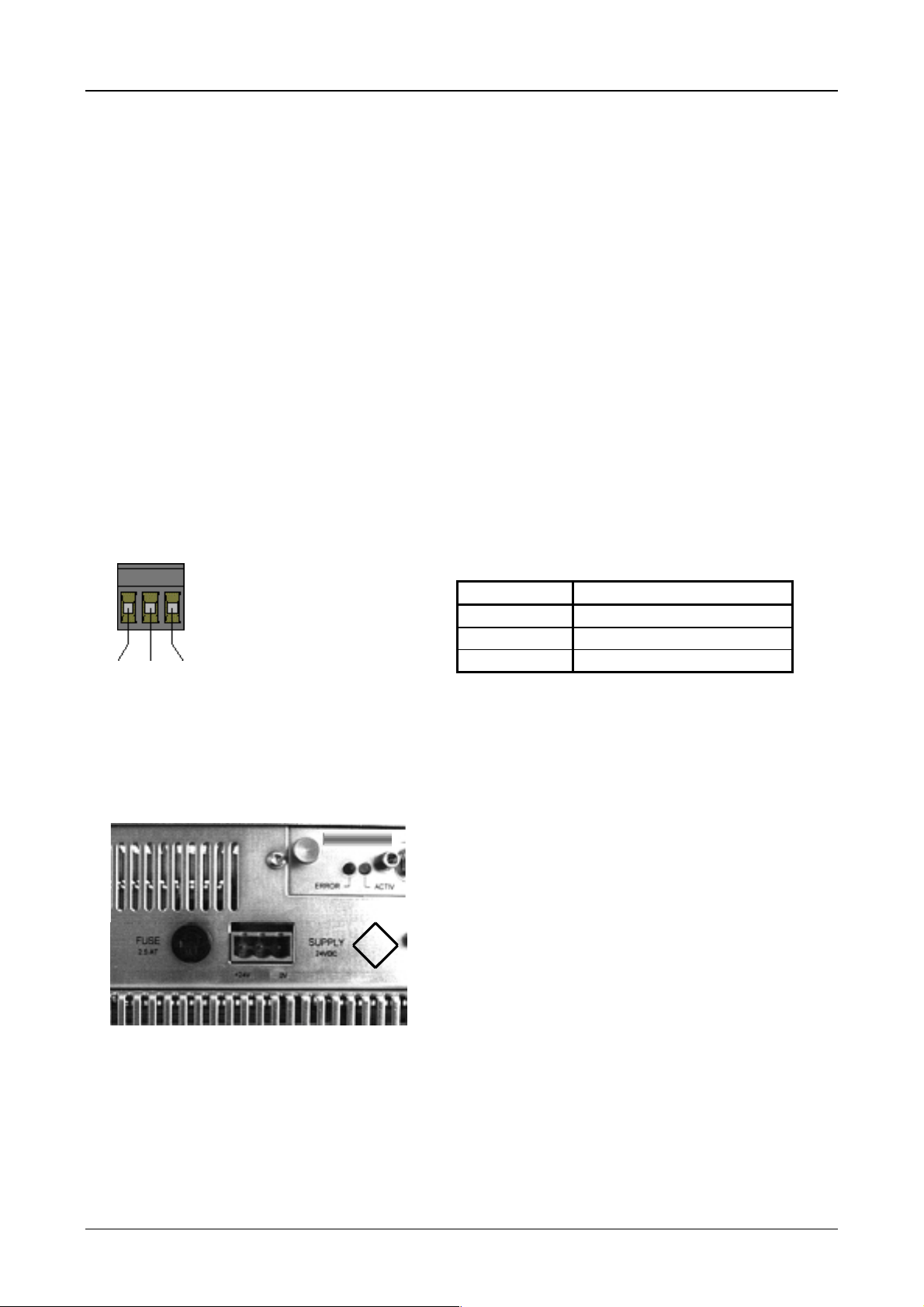
7.2 System power supply for DC Versions (24 V DC, TA1-units)
The system power suppl y of the Touch Operat or Panel is implemented via a plug-in screw terminal. T he
power supply is isolated and non-earthed (galvanically isolated), and is also fused. This can be replaced
without opening the device.
A screw terminal for the connection is supplied with the unit.
+24V PE 0V
FUSE
4.0 AT
1997
SUPPLY
24VDC
+24 V 0 V
Section of the connector panel of the unit, showing the c onnector for t he
system power supply and the fuse
Connection assignment
of supply connector
Moeller 07/01 AWB-C2700-1347GB
Page 44

Device Description MV4-570-TA1/2, MV4-590-TA1/2 2-15
7.3 System Port (Function, Assignment)
Use the System Port to
• load project data to the memory card of the Touch Oper ator Panels (Do wnload, serial link with the host
PC), as an alternative to loading project data to the memory card on the PC
• connect a serial printer for report printouts from the application
• communicate via the SUCOM-A protocol (from MV4 Configurator, V 3.03).
For SUCOM-A communic ation s elect the PLC t ype “Moe ller... PRG ” (COM) in the
MV4 Configurator. The required SUCOM-A cables ZB4-237-KB1 (for PS4) and
ZB4-233-KB1 (for PS416) must be used with an adapter (9-pol. SUB-D fem ale
connector to 9-pole SUB-D female connector).. This can be ordered under the
designation LT307.512.1 .
The programming port is a standard RS 232 interface.
CAUTION ! The system port is not isolated and is not earth-free!
8 Memory Card Slot
SYSTEM PORT
D-Sub 9 Pol male
Pin No Assignment
1 DCD
2RxD
3TxD
4DTR
5Gnd
6DSR
7RTS
8CTS
9RI (+5 V)
Case Shield
The project data for operating the T ouch Operator Panel is stored on the m emory card in the m emory card
slot. The project data is cr eate d o n P C us i ng t he re levant design software for the configurator sof t ware. If the
PC has a PC card drive, t he project dat a can be trans ferred direc tly to the m emory card. T he memor y card,
in turn, is then sim ply fitted in the memory card slot of the device. The application ca n then be started up
after switching on the system power supply.
If the PC does not have a PC card drive, a direct program downloa d on W indows 95 is possible v ia the CO M
PORT of the MV4 unit. The program download via the COM PORT is very long. With Windows NT a
download via the COM PORT is not possible.
Refer to the MV4 documentation for further information.
The Memory Card is not supplied with the Touch Operator Panel.
SYSTEM SLOT 0
MEMORY CARD SLOT
Section of the connector panel on the device, showing the Memory Card Slot and the open System Slot 0
CAUTION ! When operating Touch Operator Panel secure the memory card
by using the card retaining device supplied!
The secure fitting of the memory card in the slot cannot be guaranteed
without the use of the retaining device, especially when the device is fitted
in the normal vertical position.
Card retaining device for the memory card slot
Moeller 07/01 AWB-C2700-1347GB
Page 45

Device Description MV4-570-TA1/2, MV4-590-TA1/2 2-16
9 The Touch Screen
9.1 Basic function of the Touch Screen
The function of T ouch Screen is based o n the active light m atrix principle in the infrared range. The optical
elements of the light m atrix are located behind the IR transparent plastic f rame in the front of the device.
They are located in such a way that their radiation extends slightly out of the front plate. Each emitter is
assigned a receiver that is located on the other side. In this way a total of 70 IR channels are arranged
closely together. A touch on the screen is detected by the simultaneous interruption of one or several
channels in the X or Y axis.
Repeated touches and touches that c over an area greater t han 20 mm ⫻ 20 mm are not evaluated by the
touch controller. Continuously interrupted channels caused by severe contamination and dirt, or by the failure
an optical element, are detected by the touch controller and are no longer included in the evaluation.
9.2 Power up function test
The device runs through a function test of the Touch Screen with ever y start-up. All the IR cha nnels are
evaluated and their si gnal levels c ompared with t hose of the init ial values. T he initial va lues are determ ined
before the device is delivered and stored in a retentive memory.
If one or several channel signa ls is below a minim um relative t o the initia l level, this will be indicate d on the
screen with an error m essage and the
this kind is norm ally due to se vere co ntam ination of the IR tr anspa rent pl astic f ram e which c ons equent ly has
to be cleaned (see Section 9.3). The Touch Screen, however, remains fully functional.
Only an increase in the contam inat ion of the s c r een will le ad t o th e c ont in uous inter ru pti ons of on e or s e vera l
IR channels. IR channels tha t are continuously interrupted will be detected by the touch controller and no
longer included in the evaluation . In ex trem e cas es, this m ay mean that i ndiv idual zones c annot be ac tivate d
by touch.
DEF/DIRTY
LED will be lit (see Section 10). A reduced signal leve l of
CAUTION ! Do not touch the screen whilst the system is being started up,
and wait till your application has started.
The Touch Screen carries out a function test during the start up in which
the signal levels of the IR channels are measured.
9.3 Cleaning and care of the Touch Screen
For operation ensure that the s ignal lev els of th e channe ls are not s o severe ly redu ced or int errupted d ue to
excessive contamination through dirt (see Section 9.1).
Clean the inside of the plastic fram e of the device r egular ly wit h a dam p s oft c loth. Ensur e that t he surf ace is
not scratched or scoured, especially when removing hard deposits and abrasive dusts.
Do not expose the front of the device to solvents which m ay corrode and loosen the plast ic frame (frame
material: polymethylmethacrylate, PMMA).
Moeller 07/01 AWB-C2700-1347GB
Page 46
Device Description MV4-570-TA1/2, MV4-590-TA1/2 2-17
!
!
!
!
!
!
10 Function and control LEDs
The device features 3 LEDs for the function control of the touch controller (TOUCH) and one LED for
monitoring the system voltages (SUPPLY). These are arranged underneath the system slot 1.
TOUCH
DEF/DIRTY
COM
ERROR
INIT/COM
POWER
SUPPLY OK
The LED is activat ed if during th e po wer up f unctio n test of the T ouch Sc ree n th e
signal level of one or several IR channels goes below the minimum value
(see Section 9.2). A reduced signal level is cause d b y the contam inatio n of the IR
transparent plastic frame or the failure of an optical element.
If this LED is lit, clean the plastic frame at the front of the device
(see Section 9.3).
This LED is lit if there are any communication problems between the touch
controller and the system electronics. If the LED is lit intermittently or
continuously, this indicates a system fault. During nor mal operation this LED is
off.
The LED stays dark when the power supply is switched on. It becomes active
when the initialisation of the touc h controller h as been succ essfully com pleted b y
the system electronics.
Pressing the Touch Screen will deact iv ate the LED for about 0.3 seconds.
When lit, this LED indicates that the system voltages (+12 V and +5 V) are
present.
If the LED is not lit, altho ugh the s upply volt age has b een switc hed on, chec k the
fuse.
When the supply voltage is switched on, all 3 Touch Screen monitoring LEDs ar e activated for 0.3 seconds
for a functional check.
SYSTEM PORT
! ! !
! ! ! !
Section of the device connector panel, showing the control LEDs, the SYSTEM PORT and the SYSTEM SLOT 1 with blind plate
SYSTEM SLOT 1
! !
SUPPLY
OK
INIT /
COM
TOUCHPOWER
COM
ERROR
DEF /
DIRTY
Moeller 07/01 AWB-C2700-1347GB
Page 47

Device Description MV4-570-TA1/2, MV4-590-TA1/2 2-18
11 Communication Modules and System Expansion (Slot 0, Slot 1)
The Touch Operator provides two slots for communication modules.
The different comm unication modules ava ilable allow the Touch Sc reen to be connected t o the automation
system or the field bus system required. The us e of two com munication m odules allo ws two com municatio n
systems to be operative at the same time.
For further information refer to Parts 3 and 4 (Communication cards).
CAUTION ! Do not handle the plug-in cards (modules) without observing the relevant
safety measures concerning electrostatic discharge (ESD).
Do not fit the modules with the power supply switched on.
Only operate the modules once they have been screwed into position.
Do not operate non-Moeller components in the slots.
Only the original Moeller hardware must be used.
Moeller 07/01 AWB-C2700-1347GB
Page 48

Device Description MV4-570-TA1/2, MV4-590-TA1/2 2-19
12 Installation Instructions
12.1 Device installation
When installing the Touch Operator Panel, a minimum distance of 10 cm must be ensured between the
device and any other components, so that the cooling of the system is not impaired. The cooling slits must
not be covered by cables or other objects.
The specified operating temperature (see Section 5) is based on a vertical mounting with unhindered air
convection and a location of no more than 2000 m above sea level.
Avoid the exposure of the flat screen to direct sunlight. The radiation from the sun (UV component)
reduces the lifespan of the liquid crystal.
12.2 Mounting to IP 65
a) Installation of the unit with 4-hole aluminium front
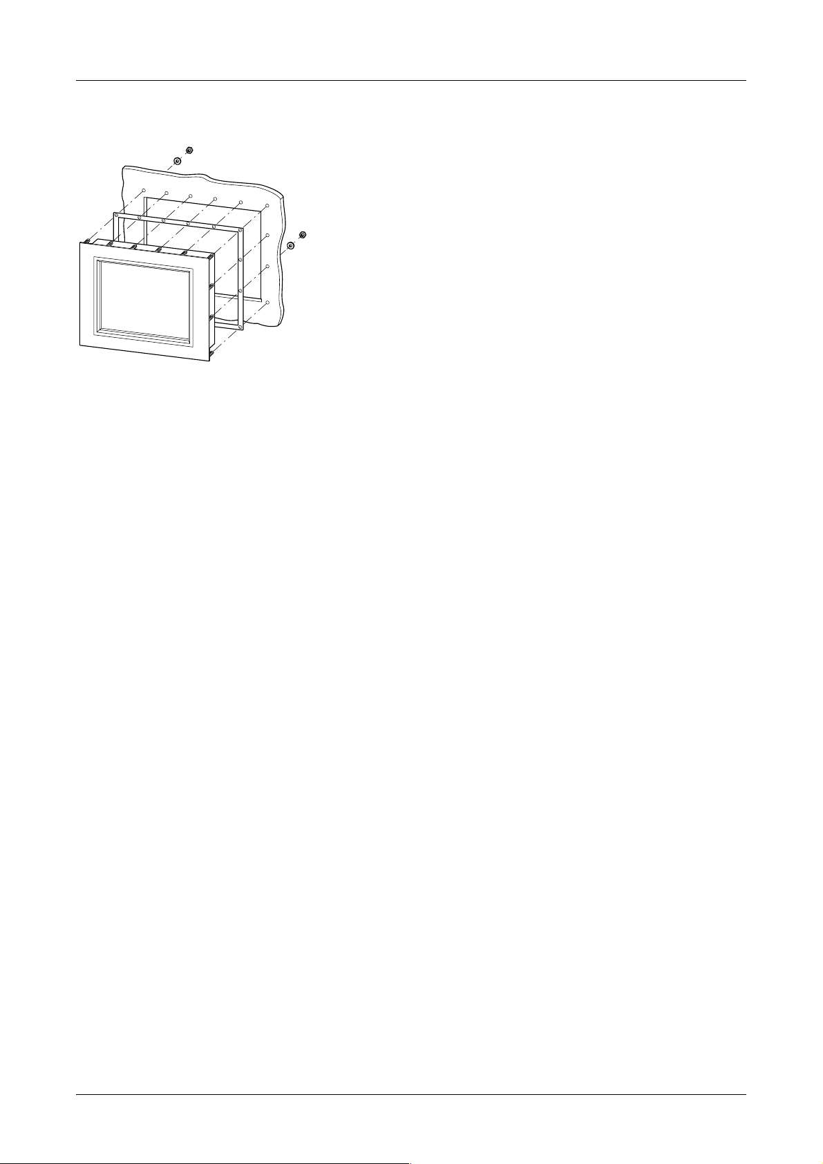
For installations requiring IP 65 compliance the supplied conter frame and seal must be used.
These ensure the necessary pressure required for mounting in thin panels.
Special care should be taken during mounting to ensure correct sealing to IP 65.
1. Fit the front seal from the rear of the device.
2. Insert the unit into the panel cutout from the.
3. The front seal must fit evenly between the front plate and the front panel.
4. Fit the conter frame from the rear of the device.
5. Tighten the countersunk screws on the device through the front panel onto the conter frame.
The countersunk screws must be tightened uniformly and securely.
6. Ensure the correct positioning and even pressure of the front seal.
Observe the general mounting instructions (refer to section 6.1).
Moeller 07/01 AWB-C2700-1347GB
Page 49

Device Description MV4-570-TA1/2, MV4-590-TA1/2 2-20
b) Installation of the units with a stainless steel front
Special care should be taken during mounting to ensure correct sealing to IP 65.
1. Slide the front seal from the rear over the unit cover onto the fixing bolts.
2. Place the device from the front into the housing cutout.
3. The front seal must be make flat and uniform contact between the front plate and front cover.
4. The nuts must be uniformly and securely tightened.
5. Ensure correct positioning and application of even pressure of the front seal.
Pay close attention to the mounting instructions (refer to section 6.1).
12.3 Preparation of the connection cables (EMC)
The preparation of the data and signal cables is an important factor in the electromagnetic compatibility
(EMC) of the Touch Operator Panel, both in terms of interference immunity and emission.
The EMC values stated in the technical data can only be guaranteed if the cables are prepared
according to the following specifications.
All data cables on the Touch Operator Panel (System Port) and on the m odules in the slots (Slot 0 and
Slot 1) must be shielded unless unshielded wiring is expressly stipulated. The power supply cable is not
shielded.
The cable shield must be made from copper braid. Only use a metal or metallised connector casing. Connect
the cable shield dir ectly to the low-impeda nce connector casing on th e Touch Oper ator Panel. T his ensur es
that the cable scr een is properly connected to th e housing of the devic e via the screws a nd the protective
metal shroud of the plug connector (low-impedance).
Cables must also be shielded if they are disconnected at the other end or are only connected during
commissioning or serv ic ing .
Refer to the relevant operatin g ins tructio ns of the PLC m anufac turer f or the c orrect connecti on procedur e for
the cable shield at the other end. Unless otherwise stated, connect the cable shield to the metal or metallised
connector casing on the PLC.
Avoid leaving th e shield ope n. T he data connec tions to b e shiel ded inv olve the hig h-spee d transf er of digita l
signals between two active systems. The cable shield only functions against asymmetrical interference
transients if the shield is connected to the device earths (usually metallic device casing) at both ends.
Provide a potential equalis ation cable with a suitable cross- section between potentials (c ontrol cabinets) if
the Touch Operator Panel and the communication partner are installed in different control cabinets or at
different PE potent ia ls (zero conductor potentia ls ) , an d if the c abl e s hie ld is dir ec t l y or in dir ec t l y c onn ec ted at
both ends to the protective earth conductor. This will prevent the occurrence of excessive compensation
currents on the shiel d and shield connec tions, as ma y occur in the event of a pos sible shorting of a device
on the protective earth system. These kinds of compensation currents of normally 50 Hz even occur in
normal operation and do not represent a problem for data transmission. However, they may cause the
destruction of the shield contacts, particularly in the event of short-circuits in the environment.
Moeller 07/01 AWB-C2700-1347GB
Page 50

Device Description MV4-570-TA1/2, MV4-590-TA1/2 2-21
12.4 Preparing the shield connections
The Touch Operator Panel and the modules in the slots are usually connected with D-Subm iniature plug
connectors in accordance with DIN 41 652. Only use metal or metallised connector casings with a cable
clamp for strain rel ief fastened on one side of the connector. The clam ping of the cable sh ield ensures an
optimum contact area and low impedance connection with the connector casing of the Touch Operator
Panel.
The following procedure is recommended for making the low-impedance connection for the cable shield:
1. Strip the cable.
2. Shorten the exposed shield braid by approx. 3 cm.
3. Turn back the braid over the cable sheath.
4. Use a heat shrinkable tubing or insulatio n tape to cover the exposed cable sheath with the folded
back screen braid so t hat 5 to 8 m m of exposed c able shield is left at the s heath end and is cleanl y
covered at the back.
5. Fit the connector.
6. The cable is then fastened at the exposed shield braid and the cable sheath below it directly
underneath the cable clamp strap of the connector casing.
Shield braid pulled
back over the
cable sheath
Heat shrinkable
tubing for covering
the shield braid
Metal or metallised
connector casing
Fastening
screws
Metallic
connector shroud
D-subminiature connector
Strap for cable clamp
and contacting of the
cable shield with the
connector casing
If other plug connect ors are used for the modules in the s lots (i.e. not D-Subminiature p lug connectors to
DIN 41 652), follow the instructions for the modules concerned.
Moeller 07/01 AWB-C2700-1347GB
Page 51

Device Description MV4-670-TA1/2, MV4-690-TA1/2 3-1
Part 3
Touch Operator Panel
Device Description
MV4-670-TA1/2
MV4-690-TA1/2
Moeller 07/01 AWB-C2700-1347GB
Page 52
Device Description MV4-670-TA1/2, MV4-690-TA1/2 3-2
Proper use
The device must only be used for the applic ations specified in the devic e description and only in c onjunction
with the components recommended by Moeller GmbH.
Warning
The trouble-free and safe operation of the product is only possible if the require ments for proper
transport, storage assembly, installation and careful operation are fulfilled.
The device must not be switched on when it is covered with condensation. When changing its
location from cold to warm the device must be allowed to acclimatise to the new conditions before
commissioning.
No warranty claims will be recognised for faults arising from the improper handling of the device.
The device should not be used for the implementation of any s afety functions rela ting to the protection of
personnel and machinery.
No liability is accepted for claims for damages arising from a failure or functional defect in the
device.
All data specified in this document does not represent guaranteed specifications in the legal sense.
Safety instructions for the user
This device description contains the information required for the proper use of the products
described therein. Sections 1 to 14 address technically qualified personnel and sections 15 to 22
address personnel not requiring any technical knowledge.
Qualified personnel in the sense of the safety instructions given in this device description or on
the project itself are persons who:
- as engineering personnel are either familiar with the safety concepts of automation,
- or as operating personnel, are instructed in the use of automation components and are
familiar with the contents of this device description relating to the operation of the device,
- or as commissioning or service personnel are suitably trained for the repair of
automation devices and are authorised to commission circuits and device/systems in
accordance with standard safety engineering principles.
Moeller 07/01 AWB-C2700-1347GB
Page 53

Device Description MV4-670-TA1/2, MV4-690-TA1/2 3-3
CONTENTS
1 Explanation of Symbols ........................................................................................................................ 3-4
2 Introduction........................................................................................................................................... 3-5
3 Device Versions / Type Designation..................................................................................................... 3-5
3.1 Scope of Delivery ............................................................................................................................ 3-6
4 Device Mounting................................................................................................................................... 3-7
4.1 General mounting instructions......................................................................................................... 3-7
4.2 Dimensions for 10.4″ devices.......................................................................................................... 3-8
4.3 Front panel cutouts for 10.4″ devices.............................................................................................. 3-9
4.4 Dimensions for 15″ devices........................................................................................................... 3-10
4.5 Front panel cutouts for 15″ devices............................................................................................... 3-11
5 Mounting Instructions ......................................................................................................................... 3-12
5.1 Installation according to degree of protection IP65....................................................................... 3-12
6 Overview of the Connections and the Connector Panel..................................................................... 3-13
7 Connecting the System Power Supply ............................................................................................... 3-14
7.1 System power supply AC (100...240VAC 50/60Hz) Type MV4-670/690-TA2(-xx1)...................... 3-14
7.2 DC system power supply, isolated (24VDC) Type MV4-670/690-TA1(-xx1)................................. 3-15
8 Interface Connections and Cabling .................................................................................................... 3-16
8.1 Preparing the connection cable (EMC) .........................................................................................3-16
8.2 Preparing the shield connections .................................................................................................. 3-17
9 Connecting the Parallel Port............................................................................................................... 3-18
10 Connecting the Ethernet Interface...................................................................................................... 3-19
11 Connecting the System Port (serial, RS232)...................................................................................... 3-20
12 Download Button ................................................................................................................................ 3-20
13 Communication Cards and System Slot............................................................................................. 3-21
14 Expansion and Configuration Options................................................................................................ 3-22
14.1 System interventions .................................................................................................................. 3-22
14.2 Auxiliary voltage output on the System port (5V)........................................................................ 3-22
15 Memory Card Slot............................................................................................................................... 3-23
16 Function and Control LEDs ................................................................................................................ 3-24
17 Touch Screen ..................................................................................................................................... 3-25
17.1 Basic Touch Screen function...................................................................................................... 3-25
17.2 Power up function test ................................................................................................................ 3-25
17.3 Cleaning and maintenance of the Touch Screen ....................................................................... 3-25
18 Display Technology, Backlight............................................................................................................ 3-26
19 Maintenance and Repair .................................................................................................................... 3-26
20 Disposal.............................................................................................................................................. 3-26
21 Technical Data.................................................................................................................................... 3-27
22 EC Conformity .................................................................................................................................... 3-29
Moeller 07/01 AWB-C2700-1347GB
Page 54

Device Description MV4-670-TA1/2, MV4-690-TA1/2 3-4
1 Explanation of Symbols
Danger warnings
The following information is for your personal safety and the prevention of damage to the device described or
connected devices.
Safety instructions and warnings for the prevention of danger to the life and health of users or service
personnel, and for the prevention of damage are highlighted in this docum ent by the following pictograms.
These consist of ”Warning” and ”Information” pictograms.
Warnings indicate the following:
Death, serious injury or substantial material damage may occur if the related safety measures are not
implemented.
The individual ”Warning” pictograms have the following meaning:
CAUTION ! General !
An instruction to be observed in order to ensure protection against hazards and
the safe operation of the device. The specified procedure should be observed.
CAUTION ! Electric shock !
Persons may be exposed to dangerous voltages that occur in electrical systems.
There is a danger of electric shock if a live part is touched.
CAUTION ! Observe ESD measures !
Electrostatic discharge may destroy electronic components.
Information pictograms indicate the following:
Important information about the product or the relevant section of the document, requiring the
particular attention of the reader.
The ”Information” pictogram has the following meaning:
Description of important information.
Tips, to simplify operations.
Moeller 07/01 AWB-C2700-1347GB
Page 55
Device Description MV4-670-TA1/2, MV4-690-TA1/2 3-5
2 Introduction
The Touch Panel MV4 is a visualization unit that is provided with touch zone functions for medium to high
complexity automation systems. It meets all the requirements placed on a modern visualization unit.
The MV4 must be loaded with the necessar y project data before it can be us ed. This is stored on the plug- in
memory cards (PC cards). The project data is created and loaded using a PC and the MV4-Configurator
MV4-CFG-1 (Galileo). This software is described in separate documentation.
Two slots (SYSTEM SLOT) are provided for taking one communication card each (→ Section 13). The
communication card manages the interface to the automation device. The communication cards are not
described in this documentation. Refer to the relevant device descriptions for more information.
The MV4-600 provides an Ethernet interface as well as a serial and parallel interface for networking and
other system functions. The required connector assignments and c onnection measur es are described in this
document. The functions supported by the software are described in the online documentation of the Galileo.
This device description is a reference for the technic al data, installation, ter m inals, commissioning, operation,
and maintenance of all MV4-600 vers ions. The designation and function of the connections and signals are
the same for all versions.
3 Device Versions / Type Designation
The MV4-600 series comes in different versions ac c ording to the dimensions and resolution of the f lat s c r een
used (10.4” VGA or 15” XGA), resulting device dimensions, materials for the front plate and device fixings.
Type designation Display size Display
technology
MV4-670-TA2 (-xx1)
MV4-670-TA1 (-xx1)
MV4-690-TA2 (-xx1)
MV4-690-TA1 (-xx1)
Units with the extention –xx1 are equipped with an acid-proof stainless steel front. The standard devices have
an aluminium front.
10.4” (264 mm) TFT color VGA (640 x 480) 100...240 VAC, 50/60 Hz
10.4” (264 mm) TFT color VGA (640 x 480) 24 VDC isolated
15.0” (381 mm) TFT color XGA (1024 x 768) 100...240 VAC, 50/60 Hz
15.0” (381 mm) TFT color XGA (1024 x 768) 24 VDC isolated
Resolution Power supply
Moeller 07/01 AWB-C2700-1347GB
Page 56

Device Description MV4-670-TA1/2, MV4-690-TA1/2 3-6
3.1 Scope of Delivery
Each device version is supplied with the following accessories:
Device version:
MV4 with stainless steel front and threaded bolts
MV4-670-TA1/2-xx1
MV4-690-TA1/2-xx1
MV4 with aluminium front and threaded bolts MV4-670-TA1/2
MV4-690-TA1/2
Accessories:
16 nuts and washers for mounting the device
Seal for mounting the unit
Power supply plug connector
AC version: Prepared inlet connector
DC version: 3-pole plug-in screw terminal, Phoenix,
Type: MSTB 2.5/3-ST-5.08)
Card retaining plate for memory card slots
••
••
••
••
(attachable to device)
2 slot covers
••
(fitted on the system slots or enclosed)
Device description AWA
••
Moeller 07/01 AWB-C2700-1347GB
Page 57

Device Description MV4-670-TA1/2, MV4-690-TA1/2 3-7
4 Device Mounting
4.1 General mounting instructions
The installation of MV4-600 series devices occurs using threaded bolts. Acc essibility to the rear side of the
device must be guaranteed. The devices is installed from the rear using washers and nuts.
All mounting versions ensure a sealed mounting to IP65. The relevant mounting instructions must be
observed (→ Section 5).
Ensure that the mounting allows access to connections, status LEDs, operating elements, such as the
Download button and the memory card (PC card). Ensure sufficient space for outgoing cables (connector
housings and bending radii of cables).
The MV4-600 units can be run at a m aximum ambient temperature of 50°C (→ Section 21). The ambient
temperature refers to the air temperature in the vicinity of the lower cooling slots, with vertical mounting,
unobstructed air convection and a maximum oper ating altitude of 2000m above sea level. When mounting in
an enclosure or cabinet, the ambient temperature is likewise the air temperature inside the enclosure
concerned. In this case it is assumed that the air tem perature at the front of the device is not higher than the
temperature in the enclosure or cabinet, and there is no additional heat c aused by radiation or conduction
that has an effect on the device.
The cooling slots mus t always be free in order to ensure the proper cooling of the system. Ensure a wall
clearance of at least 3 cm on all sides of the housing, so that proper air circulation is not impaired.
Avoid exposure to direct sunlight on the flat screen, even when it is switched off. The sunlight
(UV component) and the resulting heat may damage the display.
The cooling slots must always be free in order to ensure the proper cooling of the
system.
Avoid the exposure of the flat screen to direct sunlight.
Ensure that operating elements (Download button, memory card) and connections are
still accessible when the device is mounted.
Moeller 07/01 AWB-C2700-1347GB
Page 58

Device Description MV4-670-TA1/2, MV4-690-TA1/2 3-8
4.2 Dimensions for 10.4″″″″ devices
342
86.5
270
16
312
240
33
4
Moeller 07/01 AWB-C2700-1347GB
Page 59

Device Description MV4-670-TA1/2, MV4-690-TA1/2 3-9
4.3 Front panel cutouts for 10.4″″″″ devices
Front panel cutout: 316 mm x 244 mm (centrally to fixing holes)
Moeller 07/01 AWB-C2700-1347GB
Page 60
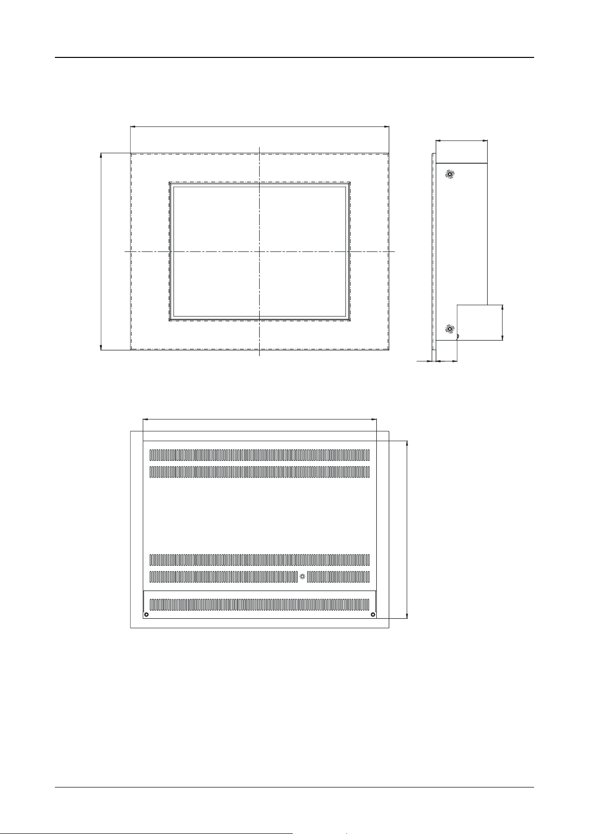
Device Description MV4-670-TA1/2, MV4-690-TA1/2 3-10
4.4 Dimensions for 15″″″″ devices
460
92
350
49
415
315
38
7
Moeller 07/01 AWB-C2700-1347GB
Page 61
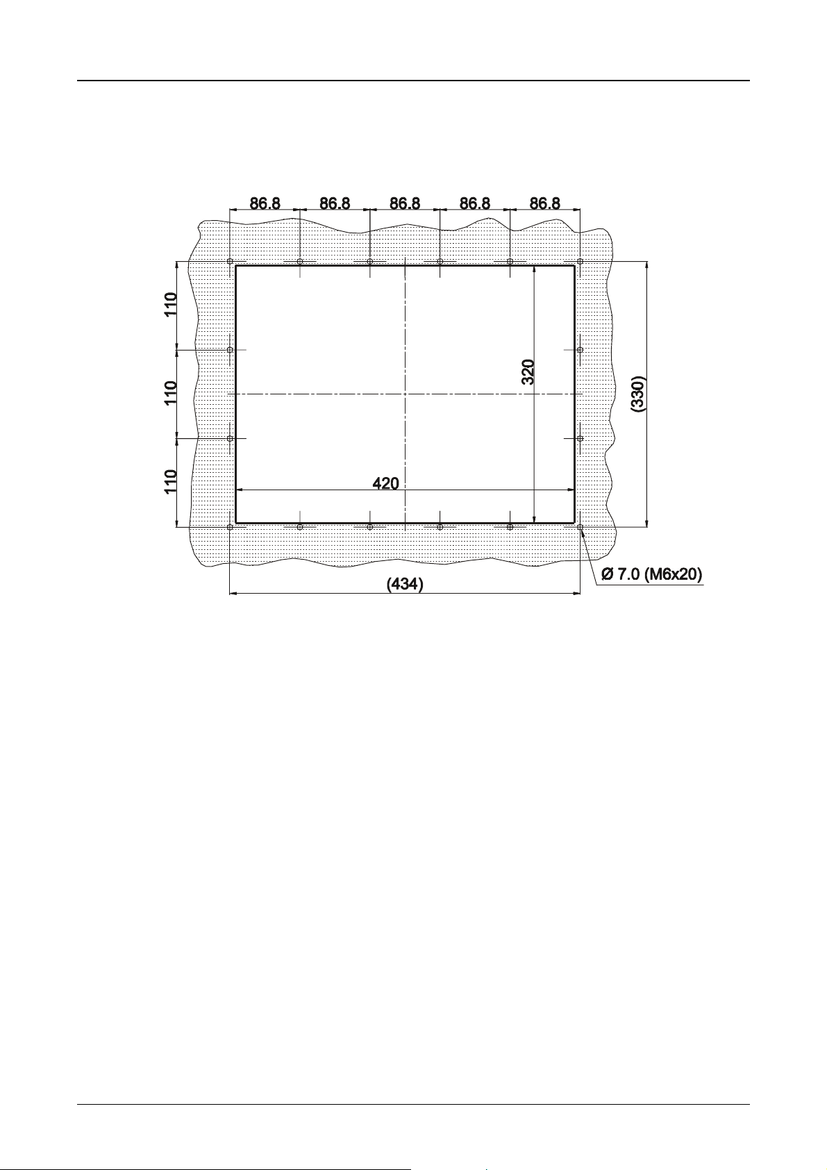
Device Description MV4-670-TA1/2, MV4-690-TA1/2 3-11
4.5 Front panel cutouts for 15″″″″ devices
Front panel cutout: 420x320 mm (centrally to fixing holes)
Moeller 07/01 AWB-C2700-1347GB
Page 62

Device Description MV4-670-TA1/2, MV4-690-TA1/2 3-12
5 Mounting Instructions
5.1 Installation according to degree of protection IP65
Mounting should be carried out with particular care in order to ensure correct sealing in compliance with IP65
protection.
1. Position the front seal from the rear over the MV4-600 and place it on the front plate.
2. Insert the device from the front into the cutout in the enclosure or cabinet.
3. The front seal must be level and evenly positioned between the front plate and the front panel.
4. The nuts must be tightened evenly and securely..
5. Check that the front seal is positioned correctly and that an even pressure is applied to it.
Observe the general mounting instructions (→ Section 4.1).
Moeller 07/01 AWB-C2700-1347GB
Page 63

Device Description MV4-670-TA1/2, MV4-690-TA1/2 3-13
6 Overview of the Connections and the Connector Panel
View of the connector panel for the MV4-670/690-TA2
View of the connector panel for the MV4-670/690-TA1
The operating elements, connections and markings are the same on the 10.4” versions (MV4-670- ...) and
15” versions (MV4-690- ...).
Moeller 07/01 AWB-C2700-1347GB
Page 64

Device Description MV4-670-TA1/2, MV4-690-TA1/2 3-14
7 Connecting the System Power Supply
7.1 System power supply AC (100...240VAC 50/60Hz)
Type MV4-670/690-TA2(-xx1)
The system power supply for the MV4 uses an inlet socket. The protection fuse is integrated in the inlet
socket and can be exchanged without having to open the device.
Normal safety standards and the specific local regulations must be observed when connecting the Panel.
L PE N
Section of connector panel for the AC version of the
MV4. View of the connector soc ket for the system
power supply with integrated fuse (1.0A sl ow).
The PE conductor must be permanently and securely connected to the PE conductor
of the power supply.
Terminal Signal
N Neutral conductor
PE Protective Earth
L Live conductor
Moeller 07/01 AWB-C2700-1347GB
Page 65

Device Description MV4-670-TA1/2, MV4-690-TA1/2 3-15
7.2 DC system power supply, isolated (24VDC)
Type MV4-670/690-TA1(-xx1)
The MV4 is compliant with protection c lass 3 and must be connected to an SELV 24VDC (safety extra-low
voltage) supply (→ Section 21). The power supply is isolated and is potential-free. The current supply is
protected with a fuse (4A slow) (→ Section 21). This c an be acc es s ed without having to open the device. T he
device is also protected against polarity reversal in the event of incorrect connection. Operation depends,
however, on correct polarity.
Normal safety standards and the specific local regulations must be observed when connecting the Panel.
The system power supply must be connected us ing a removable plug connector (3-pole). The plug connector
(socket connector screw terminals) is supplied with the device.
The following should be taken into account with the connection:
• The cross-section of the power supply cable must be at least 0.75mm² and a maximum of 2.5mm².
• A flexible lead or wire can be used for the connection.
• The cur rent consumption (→ Section 21), selectivity and disconnection c apacity in accordance with the
specified characteristics (→ Section 21) must be taken into account with the power supply connection.
• A connection to the functional ground (GND) is not compulsory for operation. The GND terminal is
directly connected to the housing potential.
+24V GND OV
(plug connector: Phoenix MSTB 2.5/3-ST-5.08)
Designation Function
+24V +24V power supply
GND Functional ground
0V 0V power supply
Section of the connector panel for 24VDC, with a
view of the system power supply socket and
fuse.
Moeller 07/01 AWB-C2700-1347GB
Page 66

Device Description MV4-670-TA1/2, MV4-690-TA1/2 3-16
8 Interface Connections and Cabling
8.1 Preparing the connection cable (EMC)
The preparation of the data and signal cables is an important factor for the electromagnetic compatibility
(EMC) of the MV4, both in terms of interference immunity and emission.
All data cables on the MV4 (SYSTEM PORT, PARALLEL PORT , ETHERNET) and on the c ards fitted in the
slots (SYSTEM SLOT) must be shielded unless unshielded cabling is specified expressly.
The cable shield mus t be made from copper br aid. O nly use a metal or metallised connector casing. Connect
the cable shield directly to the low-impedance connector casing on the MV4 This ensures that the cable
shield is properly connected to the housing of the Panel via the screws and the pr otec tive metal shroud of the
plug connector (low-impedance).
The cables must also be shielded if they are not connected at the other end and ar e only used, for exam ple,
for commissioning and servicing.
Refer to the operating instructions of the device m anufacturer s concerned as to how to connect the shield at
the other end. If no specifications are given, connect the cable shield also at this end to the metal or
metallised connector casing.
Avoid leaving the shield open. The data connections to be shielded involve the high- speed trans fer of signals
between two active systems. The cable shield only functions against asymmetrical interf erence transients if
the shield is connected to the device grounds (usually metallic device casing) at both ends.
Provide a potential equalisation conductor with a suitable cross -section between potentials (contr ol cabinets)
if the MV4 and the communications partner are installed in different control cabinets or at different PE
potentials (neutral conductor potentials), and if the cable shield at both ends is direc tly or indirec tly connected
to the protective ground conductor. This will prevent the occurrence of large com pensation currents on the
shield and shield connections. Thes e k inds of c ompensation currents of normally 50 Hz even occur in norma l
operation and do not represent a problem f or data trans m ission. However, they m ay cause the destruc tion of
the shield terminals and contacts, particularly in the event of short-circuits in the environment.
Connection work should be carried out with special care in order to ensure trouble-free
operation. The EMC values stated in the technical data can only be guaranteed if the
connections and cables are prepared according to the specifications stated.
Moeller 07/01 AWB-C2700-1347GB
Page 67
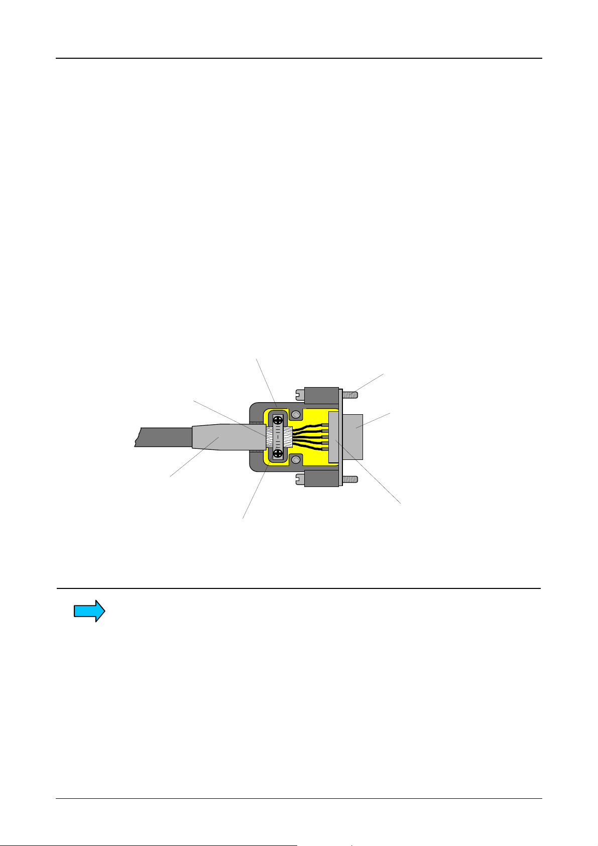
Device Description MV4-670-TA1/2, MV4-690-TA1/2 3-17
8.2 Preparing the shield connections
The connections on the MV4 and especially the card in the slot are mostly implemented with Sub-D
connectors in accordance with DIN 41652. Only use metal or metallised connector casings with a cable
clamp for strain relief fas tened or clamped on one side of the connector. The c lamping of the cable shield
ensures an optimum contact area and a low impedance connection with the connector casing of the Panel.
The following procedure is recommended for making the low-impedance connection for the cable shield:
1. Strip the cable.
2. Shorten the exposed shield braid by approx. 3 cm.
3. Turn back the braid over the cable sheath.
4. Use a heat shrinkable tubing or rubber grommet to cover the exposed cable sheath with the folded
back shield braid so that 5 to 8 mm of exposed cable shield is left at the sheath end and is cleanly
covered at the back.
5. Fit the connector.
6. The cable is then fastened at the exposed shield braid and the cable sheath below it directly
underneath the cable clamp strap of the connector casing.
Metal or metallised
connector casing
Fastening
Shield braid pulled
back over the
cable sheath
Heat shrinkable
tubing for covering
the shield braid
Strap for cable clamp
and contacting of the
cable shield with the
connector casing
screws
Metallic
connector shroud
D-subminiature connector
If different plug connectors are used for cards in the slot (not sub-D plug connectors to
DIN 41652), then follow the instructions in the relevant card descriptions.
Moeller 07/01 AWB-C2700-1347GB
Page 68

Device Description MV4-670-TA1/2, MV4-690-TA1/2 3-18
9 Connecting the Parallel Port
The programm ing port is a standar d Centronics interf ace. T he interface is not isolated. T he GND connection
is directly connected to the housing potential (→ Section 21).
Cables connected to the parallel port must be laid separately from the low-voltage cables.
PARALLEL PORT
Sub-D 25 Pole female
Pin No. Assignment Function
1 /STROBE Strobe
2 D0 Data Bit 0
3 D1 Data Bit 1
4 D2 Data Bit 2
5 D3 Data Bit 3
6 D4 Data Bit 4
7 D5 Data Bit 5
8 D6 Data Bit 6
9 D7 Data Bit 7
10 /ACK Acknowledge
11 BUSY Busy
12 PE Paper End
13 SEL Select
14 /AUTOFD Autofeed
15 Error Error
16 /INIT Initialize
17 /SELIN Select In
18 GND Signal Ground
19 GND Signal Ground
20 GND Signal Ground
21 GND Signal Ground
22 GND Signal Ground
23 GND Signal Ground
24 GND Signal Ground
25 GND Signal Ground
Case SHIELD Cable shield
Moeller 07/01 AWB-C2700-1347GB
Page 69

Device Description MV4-670-TA1/2, MV4-690-TA1/2 3-19
10 Connecting the Ethernet Interface
The Ethernet interface is implemented in accordance with the IEEE 802.3 (10/100BASE-T) standard.
The network is implemented with shielded twisted pair cable and shielded RJ45 connectors. The units
connected to the MV4-600 must also support shielded connections. The cable length and transmission speed
of twisted pair cable used for Ethernet networks mus t com ply with the relevant cable specifications. See also
the specification as per EIA/TIA 568 TSB-36.
Cables connected to the Ethernet interface must be laid separately from the low-voltage cables.
ETHERNET IEEE 802.3 10BaseT / 100BaseTX
RJ45 female
Pin No. Assignment Function
1 Tx+ Transmit cable +
2 Tx- Transmit cable -
1 8
3 Rx+ Receive cable +
4 - Not assigned
5 - Not assigned
6 Rx- Receive cable 7 - Not assigned
8 - Not assigned
Case Shield Cable shield
Function of the LEDs → Section 16.
Moeller 07/01 AWB-C2700-1347GB
Page 70

Device Description MV4-670-TA1/2, MV4-690-TA1/2 3-20
11 Connecting the System Port (serial, RS232)
The system port is a standard RS232 inter face. T he interfac e is not isolated. T he GND c onnection is directly
connected to the housing potential (→ Section 21).
Cables connected to the system port must be laid separately from the low-voltage cables.
If required, pin 9 can be assigned to the +5V supply (→ Section 21).
SYSTEM PORT
Sub-D 9 Pole male
Pin
No.
1 - Not assigned
2 RxD Receive data
3 TxD Transmit data
4 DTR Data terminal ready
5 GND Ground
6 DSR Ready for operation
7 - Not assigned
8 - Not assigned
9(+5V)
Case Shield Cable shield
Assignment Function
+5V supply (→ Section 11)
12 Download Button
The Download button is used to activate the runtime system functions. Refer to the design software
documentation for more information on the function of the Download button.
The Download button is located on the rear of the MV4. Ensure the accessibility of the device when it is
mounted.
A serial download of a project with the ZB4-244-KP1 cable is not possible on the MV4-600 devices. This
function is possible however, via the Ethernet interface.
Moeller 07/01 AWB-C2700-1347GB
Page 71

Device Description MV4-670-TA1/2, MV4-690-TA1/2 3-21
13 Communication Cards and System Slot
The MV4-600 provides two slots (System slot) for communication cards (→→→→ Section 21). The link to the
automation equipment (e.g. PLC) or the fieldbus system is implemented using one of the several
communication cards available.
Communication cards in the SYSTEM SLOT of the MV4-670-TA1
Safety precautions concerning electrostatic discharge (ESD) must be observed when
handling the cards
Never plug in the communication cards with the power supply switched on.
Only operate the communication cards once they have been fully screwed into position.
Do not run any non-Micro Innovation components in the slots. Only original hardware
from Moeller may be used.
Refer to the relevant card description for information on communication cards,
protocols, configuration, cable lengths etc.
Moeller 07/01 AWB-C2700-1347GB
Page 72

Device Description MV4-670-TA1/2, MV4-690-TA1/2 3-22
14 Expansion and Configuration Options
14.1 System interventions
The measures described in this section require the housing cover to be removed. When the device is
opened, parts are accessible that may carry dangerous voltages. Removing the housing cover and
interventions on the internal parts of the device must only be carried out after the power supply has been
switched off and the power supply plug connector has been removed.
Interventions and modifications to the device that are not described in this document will invalidate the
warranty agreement.
Interventions on the device must only be carried out after the power supply has been
switched off! During operation device compone nts carry dangerous voltage!
Safety precautions concerning electrostatic discharge (ESD) must be observed when
making interventions on the device
14.2 Auxiliary voltage output on the System port (5V)
Pin 9 of the System port →→→→ Section 11 can be used for providing exter nal additional hardware with a power
supply (+5V, jumper J10 on the main board in position B) . This is not short-circuit proof and not overload
protected and must only be used in conjunction with original Moeller hardware. The power s upply cannot be
used for non-Moeller Panel products.
Moeller 07/01 AWB-C2700-1347GB
Page 73

Device Description MV4-670-TA1/2, MV4-690-TA1/2 3-23
15 Memory Card Slot
The MV4-600 provides two slots (m emory card slot A and B) for m emory cards (PC card).Thes e memory
cards store the project data required f or running the MV4- 600. The pr oject data is created on the PC with the
appropriate MV4-Configurator (GALILEO) . If the PC has a PC c ard drive, the projec t data can be transf erred
directly to the memory card. The memory card only then needs to be fitted into the mem ory card slot of the
MV4-600. The application can then be started up by switching on the system power supply.
Further information on this is provided in the documentation of the MV4 runtime system (GRS, Galileo
runtime system).
The memory card is not supplied with the MV4-600.
View of the memory
card slots of the
MV4-600.
Use the card retaining plate supplied to prevent the memory card from falling out of
the MV4!
Without this card retaining plate a secure fitting of the memory card in the slot cannot
be guaranteed, particularly with the typical vertical mounting of the device.
Card retaining plate for
the memory card sl ot of
the MV4-600.
Moeller 07/01 AWB-C2700-1347GB
Page 74

Device Description MV4-670-TA1/2, MV4-690-TA1/2 3-24
16 Function and Control LEDs
The MV4-600 is provided with different LEDs for indicating the status of the touch controller (
Ethernet interface (
system voltages (
POWER
ETHERNET
) and the memory card slots (
). These are arranged on the connector panel.
MEMORYCARD
), as well as for monitoring the
TOUCH
DEF / DIRTY
The LED (red) is lit if during the power up function test of the Touch Screen the
signal level of one or several IR channels is below the minimum level
(→ Section 17.2). A reduction of the signal level is caused by the contamination of
the IR transparent plastic frame or the failure of at least one optical element.
If this LED is lit during norm al operation (
RUN / ACT
active), clean the plastic frame
at the front of the device (→ Section 17.3).
The LED lights up after the system voltage is switched on. It must go out by the time
active).
RUN / ACT.
the touch controller is initialised by the system electronics (
RUN / ACT
The LED (green) rem ains unlit when the system voltage is switched on. It will light
up once the initialisation of the touch controller has been successfully completed.
The LED will be deactivated for approx. 0.3 seconds when the touch screen is
pressed.
ETHERNET
LINK / ACTIVE
The LED (green) is lit if an active network is switched on and detected at the
Ethernet connector. The LED will go out momentar ily when there is activity on the
Ethernet.
100MBPS
The LED (green) is lit if the communication via the Ethernet is possible at a
transmission rate of 100 MBit/s.
If the LED is not lit, the transmission rate is 10MBit/s.
TOUCH
), the
MEMORY CARD
MEM. CARD ACCESS
POWER
SUPPLY OK
When the LED (green) is lit, the system electronics is accessing both memory
cards.
When lit, the LED (green) indicates the presence of the system voltages
(+12V and +5V, +3.3V).
If the LEDs are not lit when the system voltage is applied, check the fuse.
Section of the MV4-600 connector panel with a view of the control
LEDs, the mem ory card slot and the Ethernet interf ace.
Moeller 07/01 AWB-C2700-1347GB
Page 75

Device Description MV4-670-TA1/2, MV4-690-TA1/2 3-25
17 Touch Screen
17.1 Basic Touch Screen function
The Touch Screen operates on the active light m atrix princ iple in the infrared range. T he optical elements of
the light matrix are located behind the IR trans parent plastic fram e in the f ront panel of the device. They are
located in such a way that their radiation extends slightly out of the front pane. Each emitter is ass igned a
receiver that is located on the other side. In this way 70 closely positioned IR channels are provided on the
10.4” unit and 96 IR channels on the 15” unit (→ Section 21). A touch on the screen is detected by the
simultaneous interruption of one or several channels in the X or Y axis.
Repeated touches and touches that cover an area greater than 20 m m x 20 mm ar e not evaluated by the
controller. Continuously interrupted channels caused by severe contam ination and dirt, or by the failure of an
optical element are detected by the touch controller and are no longer included in the evaluation.
17.2 Pow e r up function test
The MV4-600 carries out a function test of the touch screen with each power up of the device. This test
measures the signal levels of all IR channels and compares them with initial signal values. The initial values
are determined before the device is delivered and stored in a retentive memory.
If the signal of one or several channels is below a minimum level relative to the initial values, this will be
indicated by an error message on the screen and the flashing of the
reduced signal level of this kind is normally due to severe contamination of the IR transparent plastic frame
which consequently has to be cleaned (→ Section 17.3). The Touch Screen, however, remains fully
functional.
Only an increase in the contamination of the sc reen will lead to the continuous interruption of one or several
IR channels. IR channels that are continuously interrupted will be detected by the Touch Controller and no
longer included in the evaluation. In extreme cas es, this m ay mean that individual zones cannot be ac tivated
by touch.
DEF/DIRTY
LED (→ Section 16). A
Do not touch the screen whilst the system is being started up, and wait till your
application has started.
During the startup the touch screen carries out a function test in which the signal
levels of the IR channels are measured.
17.3 Cleaning and maintenance of the Touch Screen
For operation ensure that the signal levels of the c hannels are not so severely reduced or inter rupted due to
excessive contamination through dirt (→ Section 17.1).
Clean the inside of the plastic frame of the device regularly with a damp soft cloth. Ensure that the surfac e is
not scratched or scoured, especially when removing hard deposits and abrasive dust.
Do not expose the front of the device to solvents which may corrode and dissolve the plastic frame
(frame material: polymethylmethacrylate, PMMA).
Moeller 07/01 AWB-C2700-1347GB
Page 76

Device Description MV4-670-TA1/2, MV4-690-TA1/2 3-26
18 Display Technology, Backlight
The MV4-600 features an active m atrix color LCD. On an LCD screen, the individual pixels are not lit. T he
image is produced by means of a back light that varies in color and intens ity on account of the individual LCD
cells (pixels).
The light of the backlight is produced by means of cold cathode tubes. The lifespan of these tubes
(→ Section 21) is limited, and depends on the relevant operating conditions. The intens ity of the brightness
and the number of start cycles are m ajor factors for the lifespan of the tubes. Reduc ing the brightness can
considerably increase the lifespan of the device. Frequent switching, particularly at low temperatures, will
reduce the lifespan of the unit.
Therefore avoid the frequent switching on and off of the backlight or the entire system. Minimising the
brightness required is more effective than reducing the frequent on/off switching.
Further information on the brightness setting of the backlight is provided in the documentation of the
GALILEO configuration software.
19 Maintenance and Repair
The MV4 is maintenance free. For trouble-free operation of the IR touch screen, clean the inner section of the
device front (front glass and IR frame) regularly (→ Section 17.3).
Repairs to the MV4 should only be carried out by the manufacturer.
20 Disposal
MV4 that are no longer used, must be properly disposed of or returned to the manufacturer.
Special note:
- The clock module contains a sealed lithium battery.
(real time clock, Dallas DS12887 or STMicroelectronics M48T86PC1)
- >LCD units are fitted with fluorescent tubes for the backlight. These contain mercury.
Moeller 07/01 AWB-C2700-1347GB
Page 77

Device Description MV4-670-TA1/2, MV4-690-TA1/2 3-27
21 Technical Data
Display
Operation
Ambient
conditions
Technology Active Matrix color LDC display (Color TFT-LCD
)
Resolution MV4-670-... 640 x 480 Pixels
MV4-690-... 1024 x 768 Pixels
Display area MV4-670-... 212 mm x 158 mm
MV4-690-... 304 mm x 228 mm
Number of colors 256
Contrast ratio (normal) MV4-670-... 1:250
MV4-690-... 1:300
Brightness (normal) MV4-670-... 250 cd/m
MV4-690-... 200 cd/m
2
2
Backlight type 2 cold cathode fluorescent tubes (CCFT), dimmable
Lifespan of backlight MV4-670-... 30,000 power on hours
(without backlight saver) MV4-690-... 30,000 power on hours
MDS TCL2, Optical light matrix in the infrared range (IR Touch →→→→ Section 17)
Physical resolution MV4-670-...
MV4-690-...
Logical resolution MV4-670-...
MV4-690-...
40 x 30 (16 x 16 Pixels)
54 x 42 (19 x 18 Pixels)
79 x 59 (8 x 8 Pixels)
107 x 83 (10 x 9 Pixels)
Operating climate 0...50°C, 10...85% rel. air humidity, non-condensing
(→→→→ Section 4)
Storage climate -20...60°C, 10...85% rel. air humidity, non-
condensing
Mechanical shock IEC 68-2-27 (1 shock, semi-sinusoidal 50g/20ms)
Vibration IEC 68-2-6 (10...200...10Hz/1.5g)
EMC interference immunity IEC 1000-4-2, EN 61000-4-2, 6 kV / 8 kV
IEC 1000-4-3, EN 50140, 10 V/m
IEC 1000-4-4, EN 61000-4-4, 2 kV
IEC 1000-4-5, asm 2kV, sym 1kV
EN 61000-4-6, ENV 50141, 10 VEMF
IEC 1000-4-8, EN 61000-4-8, 10 A/m
ENV 50140, 10V/m
Emission CISPR 22, EN 55022, Class A
Interference voltage CISPR 22, EN 55022, Class A
Degree of
protection
Front IP 65 (NEMA 12), to EN 60529
IP65 protection only with additional mounting kit!
(→→→→ Section 5.2)
Rear IP 20
Front plate
Weight
Float glass 3 mm, non-reflective
MV4-670-... Approx. 6.0 kg
MV4-690-... Approx. 8.5 kg
Dimensions
Front MV4-670-... 342 x 270 mm
MV4-690-... 460 x 350 mm
Rear MV4-670-... 310 x 240 x 86.5 mm
MV4-690-... 415 x 315 x 92 mm
Moeller 07/01 AWB-C2700-1347GB
Page 78

Device Description MV4-670-TA1/2, MV4-690-TA1/2 3-28
System supply
Fuse protection
Rated voltage MV4-...-TA2-... 100...240 VAC, 50/60 Hz
MV4-...-TA1-... 24 VDC SELV,
safety extra low voltage
(→→→→ Section 6)
Voltage range MV4-...-TA2-... 85...264 VAC, 48...62 Hz
MV4-...-TA1-... 24 VDC to DIN 19240
20.4...28.8 VDC effective, absolute
value with ripple 18.5...30.2 VDC
35.0 VDC for a duration of < 100ms
Voltage dips MV4-...-TA1-... 5 ms max., at 20.4 VDC to 0 VDC,
repetition rate 1 s
Protection against reverse
Yes
polarity
Potential isolation MV4-...-TA2-... Yes
MV4-...-TA1-... Yes
Current consumption MV4-...-TA1-... 1.4 A (normal)
Maximum inrush current MV4-...-TA2-... 32 A at 230 VAC, 17 A at 110 VAC
MV4-...-TA1-... 3.0 A
2
s
Power consumption Approx. 30 W
Inside the unit MV4-...-TA2-... 1 A slow
(accessible from outside,
→→→→ Section 7.1)
MV4-...-TA1-... 4 A slow, to EN 60127-2/2
(accessible from outside,
→→→→ Section 7.2)
MV4-...-TA2-... 35 AMaximum disconnection
capacity MV4-...-TA1-... 10 A
System slot
Network
Parallel port
System port
Memory card slot
Number 2
Type Fast Ethernet 100Base-TX IEC 802.3u (100 MBit/s)
Ethernet 10Base-T IEC 802.3 (10 MBit/s)
Connection RJ45 female
Transmission rate 10/100 MBit/s
Type
Centronics compatible, not potential-free (→→→→ Section 9)
Connectors Sub-D 25 pole female
Type
RS 232, not potential-free (→→→→ Section 11)
Connection Sub-D pole male
PC card to JEIDA/PCMCIA Type I or Type II
Technology Linear flash, 5V/5V or 5V/12V
ATA flash
Moeller 07/01 AWB-C2700-1347GB
Page 79

Device Description MV4-670-TA1/2, MV4-690-TA1/2 3-29
22 EC Conformity
The MV4-600 m eets the requir em ents spec ified by the EC Council Direc tives for harm onizing the regulations
of EC member states relating to electromagnetic compatibility (89/336/EEC) and electrical safety (LowVoltage Directive 73/23/EEC).
The generic standards below were used to assess the electromagnetic compatibility of the MV4-600:
EN 50081-2
(Emission)
EN 50082-2 (Immunity)
The following standard was used to assess the electrical safety of the MV4-600:
EN 60950
2001
Manufacturer: Moeller GmbH
Manufacturer address: Hein-Moeller-Strasse 7 - 11
53115 Bonn
Deutschland
Moeller 07/01 AWB-C2700-1347GB
Page 80

Communications Card Description ZB4-601-IF1, ZB4-609-IF1 4-1
Part 4
Communications Card
Description
ZB4-601-IF1
ZB4-609-IF1
CAUTION !
The device should only be installed by qualified personnel,
observing the instructions given in section 4 and 5 of this
document.
No guarantee claims will be recognised for faults arising from the
improper handling of the device.
The panel should not be used for the implementation of any safet y
functions relating to the protection of personnel and machinery.
No liability is accepted for claims fo r damages arising from a failure
or functional defect in the device.
Moeller 07/01 AWB-C2700-1347GB
Page 81

Communications Card Description ZB4-601-IF1, ZB4-609-IF1 4-2
CONTENTS
1 Introduction .....................................................................................................................................................4-4
1.1 Interface connection ZB4-609-IF1.................................................................................................... 4-4
2 Configuration ..................................................................................................................................................4-5
2.1 ZB4-601-IF1..................................................................................................................................... 4-5
2.2 ZB4-609-IF1..................................................................................................................................... 4-6
3 Firmware.........................................................................................................................................................4-7
3.1 ZB4-601/609-IF1.............................................................................................................................. 4-7
4 Preparing the communication cables ............................................................................................................ 4-8
4.1 Communications cable..................................................................................................................... 4-8
4.2 Cable lengths ................................................................................................................................... 4-8
4.3 Shield connection............................................................................................................................. 4-9
4.4 SIMATIC S7 – MPI........................................................................................................................... 4-9
5 Commissioning.............................................................................................................................................4-10
6 Driver List ZB4-601/609-IF1.........................................................................................................................4-11
7 Driver Types .................................................................................................................................................4-12
7.1 BCI 1.0 ........................................................................................................................................... 4-12
7.2 BCI 2.0 ........................................................................................................................................... 4-12
7.3 Driver Selection Errors................................................................................................................... 4-12
Moeller 07/01 AWB-C2700-1347GB
Page 82

Communications Card Description ZB4-601-IF1, ZB4-609-IF1 4-3
8 BCI 1.0 Drivers .............................................................................................................................................4-13
8.1 Mitsubishi ....................................................................................................................................... 4-13
8.2 Siemens ......................................................................................................................................... 4-15
8.3 Siemens S7.................................................................................................................................... 4-19
8.4 Omron ............................................................................................................................................ 4-21
8.5 Allen-Bradley.................................................................................................................................. 4-22
8.6 Matsushita...................................................................................................................................... 4-26
8.7 Texas Instruments.......................................................................................................................... 4-28
8.8 Elin Eldatic...................................................................................................................................... 4-29
8.9 Festo .............................................................................................................................................. 4-30
8.10 AEG Modicon................................................................................................................................. 4-31
8.11 Telemecanique............................................................................................................................... 4-32
8.12 Honeywell....................................................................................................................................... 4-35
8.13 Jetter .............................................................................................................................................. 4-36
8.14 ABB ................................................................................................................................................ 4-38
8.15 Westinghouse................................................................................................................................. 4-39
8.16 MDS................................................................................................................................................ 4-40
8.16.1 Data transfer protocol ............................................................................................................. 4-41
8.16.2 Control characters................................................................................................................... 4-41
8.16.3 Data format ............................................................................................................................. 4-41
8.16.4 Troubleshooting ...................................................................................................................... 4-42
8.16.5 Send TP1 procedure command.............................................................................................. 4-42
8.16.6 Send TP2 procedure command.............................................................................................. 4-42
8.16.7 Notes....................................................................................................................................... 4-43
8.16.8 Receive TP1 procedure command......................................................................................... 4-43
8.16.9 Receive TP2 procedure command......................................................................................... 4-44
8.16.10 Special not e......................................................................................................................... 4-44
8.16.11 Implementation aids ............................................................................................................ 4-44
8.17 Seitec ............................................................................................................................................. 4-45
8.18 Selectron ........................................................................................................................................ 4-46
9 BCI 2.0 Drivers .............................................................................................................................................4-47
9.1 Siemens S7.................................................................................................................................... 4-47
9.2 B & R.............................................................................................................................................. 4-49
9.3 Hapa............................................................................................................................................... 4-51
9.4 Moeller PS40.................................................................................................................................. 4-52
Moeller 07/01 AWB-C2700-1347GB
Page 83

Communications Card Description ZB4-601-IF1, ZB4-609-IF1 4-4
1 Introduction
This document ser ves as a reference for th e connection, com missioning and op eration of the ZB4-601-IF 1,
ZB4-609-IF1 communication cards.
These cards must only be used in T ouch Operator Pane ls of the MV4 ser ies which provide the appropriate
slot (destination hardware).
It must be ensured that the cards are only fitted or removed from the device when the power supply is
switched off. Ensure that the cards are only fitted or removed when the power supply is switched off.
The ZB4-601-IF1 car d supports all dri vers and physical interfaces for a wide r ange of PLC types which are
described later in this documentation.
In addition to the ZB4-601-IF1 drivers, th e ZB4-609- IF1 also s upports the MPI interf ace for the SIMAT IC S7.
Apart from this, both cards are completely identical.
The current firmware version determines which drivers can be supported. (see driver list on page 3-11).
Remember that when supplied the card is factory set with
RS 485 default configuration.
1.1 Interface connection ZB4-609-IF1
The ZB4-609-IF1 card is equipped wit h two interfaces. These interfaces cannot be linked (switche d) at the
same time. It would cause incalculable communication conflicts.
Note: Only one interface can be linked.
Moeller 07/01 AWB-C2700-1347GB
Page 84

Communications Card Description ZB4-601-IF1, ZB4-609-IF1 4-5
2 Configuration
2.1 ZB4-601-IF1
FRONT PANEL
ZB4-601-IF1
ACTIVERROR
COM P O R T
COM PORT The COM PORT interface can be configured via the jumpers for RS 232, TTY,
RS 422 and RS 485 protocols.
See also Interface configuration for information how to configure the interfaces.
ERROR When lit, the ERROR LED (red) indicates that t he last data transfer to th e PLC was
not executed correctly.
The LED will not go out until the next data transmission to the PLC is executed
correctly.
This LED should never be lit in normal operation.
ACTIV The green LED shou ld be lit during a n act ive data tr ansf er bet ween t he ZB4-60 1-IF1
and the PLC.
In normal operation t his LED should flash briefly (approx. 50 ms) with every data
transmission.
INTERFACE CONFIGURATION
COMPORT
RS 232
COMPORT
TTY
(Current Loop)
COMPORT
RS 485
J1 J2 J3 J4
ON
OFF
J5
B
A
J1 J2 J3 J4
DEFAULT
TTY
RS 485
COMPORT
RS 422
COMPORT
RS 422 MP
(Multi Point)
J5 – LINE TERM
Bus terminating resistors for RS 485 and RS 422.
These must be switched on when the device is either
the first or last station in the network.
(ON = switched on).
With point-to-point connections (only two stations),
these resistors must always be switched on.
COM BOARD MPB-TP (9 Pin female)
RS232
PIN
-
1
RxD
2
TxD
3
DTR
4
GND
5
DSR
6
-
7
-
8
-
9
SHIELD
CASE
PIN ASSIGNMENT
TTY
IN
-
<
-
>
-
>
GND
-
<
-
OUT
SHIELD SHIELD SHIELD
RS485
-
<
A
<>
GND
B
<>
-
-
>
RS422
DTR+
TxD+
RxD+
DSR+
GND
DTRTxDRxDDSR-
>
>
<
<
>
>
<
<
Moeller 07/01 AWB-C2700-1347GB
Page 85

Communications Card Description ZB4-601-IF1, ZB4-609-IF1 4-6
2.2 ZB4-609-IF1
FRONT PANEL
ZB4-609-IF1
ACTIVERROR
MPI
COM P O R T
COM PORT The COM PORT interface can be configured via the jumpers for RS 232, TTY,
RS 422 and RS 485 protocols.
See also Interface configuration for information how to configure the interfaces.
MPI
The MPI interface m ust only be used f or the SIMAT IC S7 and must be configured
for RS 485.
See also Interface configuration for information how to configure the interfaces.
ERROR When lit, the ERROR LED (red) indicates that t he last data transfer to th e PLC was
not executed correctly.
The LED will not go out until the next data transmission to the PLC is executed
correctly.
This LED should never be lit in normal operation.
ACTIV The green LED shou ld be lit during a n active d ata transf er between the Z B4-609-IF1
and the PLC.
In normal operation t his LED should flash briefly (approx. 50 ms) with every data
transmission.
INTERFACE CONFIGURATION
J1 J2 J3 J4
COMPORT
RS 232
COMPORT
TTY
(Current Loop)
COMPORT
RS 485
COMPORT
RS 422
COMPORT
RS 422 MP
(Multi Point)
MPI
RS 485
J5 – LINE TERM
Bus terminating resistors for RS 485 and RS 422.
These must be switched on when the device is
either the first or last station in the network.
(ON = switched on).
With point-to-point connections (only two stations),
these resistors must always be switched on.
J5
ON
OFF
COM BOARD MPB-TP (9 Pin female)
RS232
PIN
-
1
RxD
2
TxD
3
DTR
4
GND
5
DSR
6
-
7
-
8
-
9
SHIELD
CASE
B
A
PIN ASSIGNMENT
TTY
IN
-
<
-
>
-
>
GND
-
<
-
OUT
SHIELD SHIELD SHIELD SHIELD
J1 J2 J3 J4
RS485
-
<
A
GND
B
-
-
>
DEFAULT
RS485
RS 485
MPI
RS422
DTR+
TxD+
RxD+
<>
DSR+
GND
DTRTxD-
<>
RxDDSR-
RS485
>
-
-
>
Line-B
<
RTS
<
>
>
<
<
>
GND
VCC
Line-A
-
These terminating resistors must not be used for the MPI.
Moeller 07/01 AWB-C2700-1347GB
Page 86

Communications Card Description ZB4-601-IF1, ZB4-609-IF1 4-7
5
3 Firmware
3.1 ZB4-601/609-IF1
The firmware is stored on a retentive flash memory for standard or alternative drivers.
When delivered the following drivers are loaded:
• ZB4-601-IF1 drivers for Moeller PLCs (PS40.BIN)
• ZB4-609-IF1 driver for Siemens MPI (MPI.BIN)
The drivers can be updated at any time in a Touch Operator Panel (see online documentation Galileo,
chapter “Galileo Runtime System”, section “Comboard Loader”).
J6 – PRG RUN
“RUN” position activates the
appropriate drivers according to the
setting on J7.
“PRG” position allows new drivers to
be loaded (see online documentation
Galileo, Section GRS).
The setting of J7 does not have any
effect in PRG mode.
J7 – STD ALT
When set to “STD” al l MPB.B IN dri vers
will be loaded..
Set to “ALT” in order to load the oth er
drivers (see Driver list on page 3-11).
The currently loaded drivers or their
versions are displayed in the system
masks of the Touch Operator Panel.
STD ALT
ON
OFF
PRG RUN
J6
CB-
Loader
V 1.00
J7
J5
J1 J2 J3 J4
B
A
DEFAULT
RUN
DEFAULT
ZB4-601-IF1:ALT
MPB1-TP : STD
ZB4-609-IF1:ALT
MPB2-TP : ALT
DEFAULT
DEFAULT
ZB4-601-IF1:RS 485
MPB1-TP : TTY
ZB4-609-IF1:RS 485
MPB2-TP : RS48
Moeller 07/01 AWB-C2700-1347GB
Page 87

Communications Card Description ZB4-601-IF1, ZB4-609-IF1 4-8
4 Preparing the communication cables
The preparation of the cables for the serial interf ace “COM PORT” and “MPI” is an important factor in th e
electromagnetic compatibility (EMC) of the target hardware, both in terms of interference immunity and
emission.
The EMC values stated in the technical data can only be guaranteed if the cables are prepared
according to the following specifications.
4.1 Communications cable
The communications cable must be shielded. The cable shield must be made from copper braid. Use a metal
or metallised connec tor casing. Connect the c able shield for the card directly to the connec tor casing. This
ensures that the cab le shie ld is proper l y connected to the h ousing of the targ et h ard ware v ia the s cre ws a nd
the protective metal shroud of the plug connector.
Refer to the relevant operatin g ins tructio ns of the PLC m anufac turer f or the c orrect connecti on procedur e for
the cable shield to the PLC. Unl ess other wise s tated, c onn ect the c able shi eld to the co nnector casin g of the
PLC.
Provide a potential equalisation cable with a suitable cross-section between control cabinets if the target
hardware and PLC (or a nother communications partner) ar e installed in different control cabinets and the
cable shield is directl y or indirectly connected to the protec tive earth at the PLC end. T his will prevent the
occurrence of exc essive compensation curren ts on the shield and sh ield connections, as m ay occur in the
event of a possible shorting of a device on the protective earth system.
4.2 Cable lengths
The possible cable length and wire recommendations depend on the physical interface used.
Transmission errors may occur if these limits are not observed.
Interface baud rate Length Comments
RS 232 19’200 15 m
9’600 30 m Only suitable for point-to-point connections.
4’800 60 m
RS 422/485 < 100’000 1200 m Using twisted pair communication cables can increase reliability
< 500’000 600 m of the data line concerned.
< 1’000’000 120 m The line term inating resistors mus t be switched on between the f irst
and last data terminals!
TTY < 20’000 1000 m
Moeller 07/01 AWB-C2700-1347GB
Page 88

Communications Card Description ZB4-601-IF1, ZB4-609-IF1 4-9
4.3 Shield connection
Only use metal or metal lised conn ector c asings with a c able c lam p for cable a nchori ng fast ened o n one si de
of the connector. This ensures an optimum contact area and low im pedance connection with the connector
casing.
The following procedure is recommended for connecting the cable shield:
1. Strip the cable.
2. Shorten the exposed shield braid by approx. 3 cm.
3. Turn back the braid over the cable sheath.
4. Use a heat shrinkable tube or insulation tape to cover the exposed cable sheath with the folded
back shield braid so that 5 to 8 mm of exposed cable shield is left at the sheath end and is cleanly
covered at the back.
5. Fit the connector.
6. The cable is then fastene d at the exposed shield bra id and the ca ble sheath b elow it direc tly underneat h
the cable clamp strap of the connector casing.
Shield braid pulled
back over the
cable sheath
Shrinkage tube
for covering the
shield braid
Metal or metallised
connector casing
Fastening
screws
Metallic
connector shroud
D-subminiature connector
Strap for cable clamp
and contacting of the
cable shield with the
connector casing
4.4 SIMATIC S7 – MPI
For this observe in particular the installation instructions with regard to line length or stub line in
SIEMENS MPI specifications.
The use of original PROFIBUS cable and plug connector is generally recommended.
Moeller 07/01 AWB-C2700-1347GB
Page 89

Communications Card Description ZB4-601-IF1, ZB4-609-IF1 4-10
5 Commissioning
1. Connect the COM PORT of the ZB4-601/609-IF1 or “MPI” in the case of the ZB4-609-IF1 to the
appropriate communications port on the PLC.
For this use the special communications cable of the PLC (see wiring diagram from section 8).
2. Switch on the power supp ly. Active com munication is s tarted as soon as the first operati ng mask of the
loaded project is displayed.
3. When communic ation with the P LC is active, the green ACT IVE LED on t he ZB4-601 /609-IF1 will be lit.
Once communication has ended, the ACTIVE LED will go out.
The red ERROR LED will be lit if no correct data exchange with the PLC was possible.
Additional points on commissioning refer only to errors; none of the LEDs are lit or the red
ERROR LED lights up.
Otherwise commissioning at this point has ended directly.
4. If none of the two LEDs light up, this is pro bably becaus e a driver was s elected th at is not suppor ted by
the current firmware of the ZB4-601/609-IF1.
In this case ask your MDS custom er suppor t about n ewer vers ions of the ZB4-60 1/609-IF1 and note th e
error messages in the destination hardware.
Check whether the jumper J7 (STD/ALT) is set correctly for the required driver.
Other points on commissioning only refer to errors (red ERROR LED).
5. First check whether the physical interface of the ZB4-601/609-IF1 is compatible with that of the PLC
(RS 232, TTY, RS 485, RS 422).
Have you connected the ZB4-609-IF1 to the correct port (“MPI” or “COM PORT”) ?
6. Chec k the communications c able for breakage or s hort-circuits. Check the communications cable used
by means of the diagram for the PLC.
7. If the red ERROR LED is l it onl y inter m ittently, check wheth er the ca ble s hields have been c onnected as
described.
8. Wire only one of the connectors at ZB4-609-IF1 !
9. Furthermore pay particular attention to the PLC notes given in the section PLC interfaces. All the
interfaces described in this section have been tested and are used in real applications.
If the interface you r equire is not listed, try an alternative interface for the PLC and contact our support
centre.
Moeller 07/01 AWB-C2700-1347GB
Page 90

Communications Card Description ZB4-601-IF1, ZB4-609-IF1 4-11
6 Driver List ZB4-601/609-IF1
MANUFACTURER PROTOCOL DATA TYPES NOTES DRIVER
ABB Modbus I, B Masterpiece 90
AEG Modicon Modbus R, M Modicon 984
Allen-Bradley DF1 N, B PLC5 (with channel 0) MPB.BIN
DF1 (1747KE) N SLC500 (with 1747KE)
DF1 N, B SCL503 and 504 (channel 0)
B & R Mininet R, F CP60 MININET.BIN
Modbus R, M B & R 2005
Elin ECS2000 V,X,Y,I,E,A ELDATIC MC1
Festo Commando Inter. R, MW FPC405
Hapa Mininet M Hapa110 MININET.BIN
Jetter Sympas R PASE MPB.BIN
Moeller
*)
Suconet K M, MB, MW PS4-141-MM1
PS4-151-MM1
PS4-201-MM1
Suconet K M, MB, MW, MD PS4-341-MM1
PS416
SUCOM A M, MB, MW PS4-141-MM1
PS4-151-MM1
PS4-201-MM1
SUCOM A M, MB, MW, MD PS4-341-MM1
PS416
*) The connection to Moeller PLCs is described in detail in the manual AWB-C2700-1349GB.
Honeywell IPC620-ABC RG, M IPC620
Matsushita PG-Protocol DT,R,SV,EV,X,Y FB1, FP3, FP5
MDS TP1 DW Free interface
TP2 DW Free interface
Mitsubishi Computer Link M, D AJ71C24 and compatible
PG-AX M, D AX series
PG-FX M, D FX series MPB.BIN
Omron Host Link HR, IR C20
Host Link HR, DM, IR C500, K series, H series
Seitec ISY-GLT DW GLT Master
Selectron Modbus R, M SELECONTROL MAS
Siemens DK512/R3964R DW CP524/525 and compati ble
AS511 DW S5 series
R3964R DW CP521-SI (S5-AG103)
MPI DW,MW,I,O S7-31x/S7-41x MPI.BIN
Siemens TI TI500 V TI500 series
SIG SBC-2 C, D VME1
Telemecanique UNI-Telway W TSX17 MPB.BIN
UNI-Telway W TSX37
Westinghouse Modbus R, M PC1100/PC1200
MPB.BIN
PS40.BIN
Note: The driver “MPB.BIN”, must always be loaded as the standard driver.
Moeller 07/01 AWB-C2700-1347GB
Page 91

Communications Card Description ZB4-601-IF1, ZB4-609-IF1 4-12
7 Driver Types
The next section describes all the dr ivers for different PLC t ypes that have been test ed and that are used in
practise.
The connection to all PLCs is alwa ys made via the “C OM PORT ” 9-pole D-Su b inter face on the c ard, un less
MPI is explicitly specified (only SIEMENS S7).
Connection types on existing PLC types that are not listed can theoretically be derived.
Contact MDS customer support in case of problems.
Drivers for new PLC t ypes can only be implemented by the manufacturer. In this case ask about newer
versions of the communications cards or for possibilities to implement your PLC type.
7.1 BCI 1.0
BCI stands for Basic C ommunication I nterface and d escribes the ge nerally applic able definiti on for the data
exchange with the PLC.
The following definition is possible for BCI 1.0 standard drivers:
1) PLC or ZB4-601/609-IF1 station number (1 Byte)
2) Data type (1 Byte)
3) Start address (2 Byte)
4) Number of data bytes
7.2 BCI 2.0
The BCI 2.0 allows a considerably more flexible definition of the data f or the data exchange with one or
several PLCs and is used with all new driver types.
The following definition is possible for BCI 2.0 standard drivers:
1) ZB4-601/609-IF1 station number (1 Byte)
2) ZB4-601/609-IF1 slot number (1 Byte)
3) PLC station number (1 Byte)
4) PLC slot number (1 Byte)
5) Data type (1 Byte)
6) Data type (1 Byte)
7) Module address (2 Byte)
8) Start address (2 Byte)
7.3 Driver Selection Errors
Error message: GROUP NOT AVAILABLE !/DRIVER NOT AVAILABLE !
The required BCI 1.0 driver is not available in the current firmware.
Error message: BCI 2.0 DRIVER NEEDED !
The required BCI 2.0 driver is not available in the current firmware.
Error message: ONLY BCI 1.0
The required driver is only available in the current firmware as BCI 1.0 driver.
Error message: ONLY BCI 2.0
The required driver is only available in the current firmware as BCI2.0 driver.
These error mess ages indicate that your current firm ware does not yet support the lates t drivers. Contact
your customer support.
Moeller 07/01 AWB-C2700-1347GB
Page 92
Communications Card Description ZB4-601-IF1, ZB4-609-IF1 4-13
8 BCI 1.0 Drivers
8.1 Mitsubishi
MITSUBISHI
PLC Type Protocol PLC Port Parameters
A series
DRIVER DESIGNATION (2, 1) : MITSUBISHI > AJ71C24 (MPB.BIN)
SUPPORTED DATA TYPES : M, D
WIRING LIST
Computer Link AJ71C24
Format 1 (Mode 1)
9600 baud, 8 data bits, 1 stop bit, no parity
Checksum on
RS 232 RS 422
Signal Pin Pin Signal
RxD 2 2 TxD
TxD 3 3 RxD
DTR 4 6 DSR
SG 5 7 SG
DSR 6 20 DTR
8 DCD
4RTS
5CTS
ZB4-601/609-IF1 AJ71C24
(9 pole male)
(25 pole male)
Signal Pin Pin Signal
TxD+ 2 RxD+
RxD+ 3 TxD+
SG 5 SG
TxD- 7 RxDRxD- 8 TxD-
ZB4-601/609-IF1 AJ71C24
(9 pole male)
NOTES
• Check in accordance with the manual for the Computer Link Module AJ71xx whether the mentioned
parameters and interface (RS 232 or RS 422) are correctly set.
Note: the switch assignment is not identical for all AJ71xx!
• Select protocol format 1 for the AJ71xx and station number 0.
• Remember that changes to settings on the AJ71xx are not effective until the PLC has been restarted.
• Correct data transmission on the AJ71xx using RS 232 is indicated by the flashing of LEDs 2SD and
2RD, and LEDs 4SD and 4RD when using RS 422.
Moeller 07/01 AWB-C2700-1347GB
Page 93

Communications Card Description ZB4-601-IF1, ZB4-609-IF1 4-14
MITSUBISHI
PLC Type Protocol PLC Port Parameters
AX series
FX series
DRIVER DESIGNATION (2, 2) : MITSUBISHI > PG-AX (MPB.BIN)
SUPPORTED DATA TYPES : M, D
WIRING LIST
Port
Communication
Direct Access PG-Port 9600 baud, 7 data bits, 2 stop bit, parity even
PG-Port 9600 baud, 8 data bits, 1 stop bit, parity odd
Checksum on
Checksum on
(2, 3) : MITSUBISHI > PG-FX (MPB.BIN)
RS 422
Signal Pin Pin Signal
DTR+ 1 4 DSR+
TxD+ 2 2 RxD+
RxD+ 3 3 TxD+
DSR+ 4 5 DTR+
DTR- 6 17 DSRTxD- 7 15 RxDRxD- 8 16 TxDDSR- 9 18 DTRSG 5 7 SG
21 Pres
ZB4-601/609-IF1 PG AX/FX
(9 pole male)
NOTES
• No special notes;
The connection is the sam e as for the pr ogramm ing devic e provide d that all parameter s are fitte d and no
other driver or configuration is required in the PLC.
(25 pole male)
Moeller 07/01 AWB-C2700-1347GB
Page 94

Communications Card Description ZB4-601-IF1, ZB4-609-IF1 4-15
8.2 Siemens
SIEMENS
PLC Type Protocol PLC Port Parameters
S5
DRIVER DESIGNATION (3, 1) : SIEMENS > DK512 (MPB.BIN)
SUPPORTED DATA TYPES : DW
WIRING LIST
DK512 (R3964R) CP524/525/135
or compatible
9600 baud, 8 data bits, 1 stop bit, parity even
low priority
RS 232 TTY
Signal Pin Pin Signal
RxD 2 2 TxD
TxD 3 3 RxD
SG 5 7 SG
ZB4-601/609-IF1 CP524/525
(9 pole male)
PLC Type Protocol PLC Port Parameters
S5-928B
DK512 (R3964R) CP 9600 baud, 8 data bits, 1 stop bit, parity even
(25 pole male)
Signal Pin Pin Signal
IN 1 10 OUT+
SG 5 19 OUTOUT 9 14 IN-
ZB4-601/609-IF1 CP524/525/135
(9 pole male)
low priority
13 IN+
(25 pole male)
WIRING LIST
RS 422
Signal Pin Pin Signal
TxD+ 2 11 RxD+
RxD+ 3 9 TxD+
SG 5 8 SG
TxD- 7 4 RxDRxD- 8 2 TxDDTR+ 1
DSR+ 4
DTR- 6
DSR- 9
ZB4-601/609-IF1 928B-CP
(9 pole male)
Moeller 07/01 AWB-C2700-1347GB
(15 pole male)
Page 95

Communications Card Description ZB4-601-IF1, ZB4-609-IF1 4-16
NOTES
• Configure the comm unications process or used f or the spec ified par ameters and selec t the lo w priorit y for
the PLC.
• Do not program any jobs for your CP but sim ply use the standard function block s (RECEIVE_ALL and
FETCH_ALL). The ZB4-601/609-IF1 cannot accept jobs that are initiated by the CP.
• For active data exchange with the CP the function blocks mentioned must be called up in the main
program of the PLC (OB1).
• Remember that this interface is not only for the R396 4R protocol but also requ ires the DK512 (= RK512)
data interpreter.
Example:
The CPU944 can run the R3963R protocol on the second interface using the 6ES5-816-1BB21 module.
This only enables data tra nsport, however, the interpreter would have to be implem ented in the control
program of the PLC (not recommended).
Note: this CPU can also process the AS511 protocol on the second interface.
• PLC and CP must both be in Run status.
• If data blocks or data words are address ed that are not available in the PLC, this will cause errors in the
communication.
Moeller 07/01 AWB-C2700-1347GB
Page 96

Communications Card Description ZB4-601-IF1, ZB4-609-IF1 4-17
SIEMENS
PLC Type Protocol PLC Port Parameters
S5
DRIVER DESIGNATION (3, 2) : SIEMENS > AS511 (MPB.BIN)
SUPPORTED DATA TYPES : DW
WIRING LIST
AS511 PG-Port 9600 baud, 8 data bits, 1 stop bit, parity even
TTY
Signal Pin Pin Signal
IN 1 6 OUT+
SG 5 7 OUT-
9IN+
OUT 9 2 IN-
ZB4-601/609-IF1 S5 PG
(9 pole male)
NOTES
• The interface to t he PG -Port of the S5 is the s am e as for the program m ing device. N o p aram eter s ettings
or function blocks are required.
(15 pole male)
• With CPUs that have two interfac es it is b es t to us e th e s ec on d o ne s inc e us u al l y not all PG f unc tions are
available on this. All the functions of the ZB4-601/609-IF1 can be implemented with this port.
• The PLC must be in Run status for active communication.
• If both data bloc k s or data wor ds ar e addres sed that are not av ailab le in the PL C, this will c ause er rors in
the communication.
Moeller 07/01 AWB-C2700-1347GB
Page 97

Communications Card Description ZB4-601-IF1, ZB4-609-IF1 4-18
SIEMENS
PLC Type Protocol PLC Port Parameters
S5-103
DRIVER DESIGNATION (3, 4) : SIEMENS > CP521-SI (MPB.BIN)
SUPPORTED DATA TYPES : DW
WIRING LIST
R3964R CP521-SI 9600 baud, 8 data bits, 1 stop bit, parity even
RS 232 TTY
Signal Pin Pin Signal
RxD 2 2 TxD
TxD 3 3 RxD
SG 5 7 SG
ZB4-601/609-IF1 CP521-SI
(9 pole male)
NOTES
• The AG103 with the CP521-SI supports the R3964R protocol.
(25 pole male)
Signal Pin Pin Signal
IN 1 18 OUT+
SG 5 21 OUTOUT 9 10 IN-
ZB4-601/609-IF1 CP521-SI
(9 pole male)
9IN+
(25 pole male)
• An interpreter with a scale d-down versio n of DK512 (max 4 data byte) can be obtained for this PLC f rom
Moeller.
• If the interpreter is implemented in the PLC (see appropriate documentation), the ZB4-601/609-IF1 is
capable of implementing RECEIVE and FETCH jobs as with the CP524.
• The PLC must be in Run status for active communication.
• If both data bloc k s or data wor ds ar e addres sed that are not av ailab le in the PL C, this will c ause er rors in
the communication.
Moeller 07/01 AWB-C2700-1347GB
Page 98

Communications Card Description ZB4-601-IF1, ZB4-609-IF1 4-19
8.3 Siemens S7
SIEMENS S7
PLC Type Protocol PLC Port Parameter
S7-31x
S7-41x
DRIVER DESIGNATION (3, 6) : SIEMENS > MPI-PREREL (MPI.BIN)
SUPPORTED DATA TYPES : DB:DBW
WIRING LIST
MPI PG-Port (MPI) 187.5 kbaud
MPI (RS 485)
Signal Pin Pin Signal
LINE-B 3 3 LINE-B
LINE-A 8 8 LINE-A
RTS 4
SG 5
VCC 6
ZB4-601/609-IF1 S7-MPI
(MPI 9 pole male)
NOTES
(9 pole male)
• The interface to the SIMATIC S7 is connected directly via the PG Port (MPI).
The connection therefore does not require any parameter setting or the activation of any function blocks.
• Standard PROFI BUS cabl es an d connec tors ( MPI cor respon ds ph ysica lly to PRO FIBU S) are re quired for
connecting the individual stations in the MPI network. Please note, for installation of link cable, refer to the
specification of SIEMENS Section MPI, regards length of cables and installation.
• The ZB4-609-IF1 card must be set to “ALT” and the current MPI driver (MPI.BIN) must be loaded
(see also section 3.1).
• The bus term inating resistors must be s witched on at the cabl e ends (last stations) , with at least one of
the stations being energised so that the terminations are supplied with power. With the standard
PROFIBUS cables this can be switched on using the slide switches in the connector housing.
Line termination in accordanc e with DIN EN 50 170/2.
VCC 390 ΩΩΩΩ 220 ΩΩΩΩ 390 ΩΩΩΩ GND
BA
The bus terminating resistors on the communications card MUST NOT be switched on!
Moeller 07/01 AWB-C2700-1347GB
Page 99

Communications Card Description ZB4-601-IF1, ZB4-609-IF1 4-20
NOTES ON SIMATIC 7 (Continuation)
• The ZB4-609-IF1 is permanently assigned station number 1.
Ensure, however, that no other station in the MPI network is assigned this station num ber (no double
assignments).
Check with the PG under “ Accessible Nodes ”, whether station 1 is already assigned.
Station number 0 is reserved for the PG.
Station number 2 is the default setting for the PLC
• The HSA (Highest System Addres s) mus t be the same f or all stations in the net work (15, 31, 6 3 or 126).
If declaration is wrong or missing, the ZB4-609-IF1 will use 126.
• As soon as the ZB4-609-IF1 is c onnected with the param eterized PLC in the M PI network, you will see
this under station number 1 in the PG under “ Accessible Nodes ”.
The PG cannot, however, be us ed to es tablish a c onnect ion to this station . If, howev er, this is attem pted,
the ZB4-609-IF1 will refuse this connection. The PG will then output the message “Station refuses
connection establishm ent” .
The ZB4-609-IF1 can only establis h active co nnection wit h one parameteri zed MPI station (S IMATIC S7
PLC).
• The individual data blocks can be assigned as follows:
– 1 char Data type (“D” = DB:DBW)
– 1 byte Module address (corresponds to the DB number)
– 1 byte Data address
Note in particular h ere that wor d values ar e genera lly trans ferred. W hen transf erring data bytes, the Hi gh
and Low word in the PLC is opposite to that of the display.
• With PLC byte processing, the start addresses of data words are generally doubled.
This means that, for example, DB5:DW5 is DB5:DW10 in the PLC.
• An error mess age will be output, if the param eterized destination statio n (PLC) is not available or if the
network is not connected.
The number after ST# corresponds to the missing MPI station number in hexadecimal format.
MPI 1.52 ST#02 CONNECT?
• If the module address or data address is not available, the following message is output:
MPI 1.52 ST#02 ADDRESS!
Since the ZB4-609-IF1 always transfers data blocks of at least 2 bytes, only the access to the data
address is checked and not the subsequent addresses.
Following addresses that are not present are ignored and do not initiate error messages.
• If no errors occur with the data transfer, the following message will be output:
MPI 1.51 ST#02 READY !
The messages and error mess ages are generated by the Z B4-609-IF1 after ever y data transfer. These,
however, are only displayed in the MMI in the event of a c hange (error af ter Read y) or sporadica lly if the
error stays the same.
Moeller 07/01 AWB-C2700-1347GB
Page 100
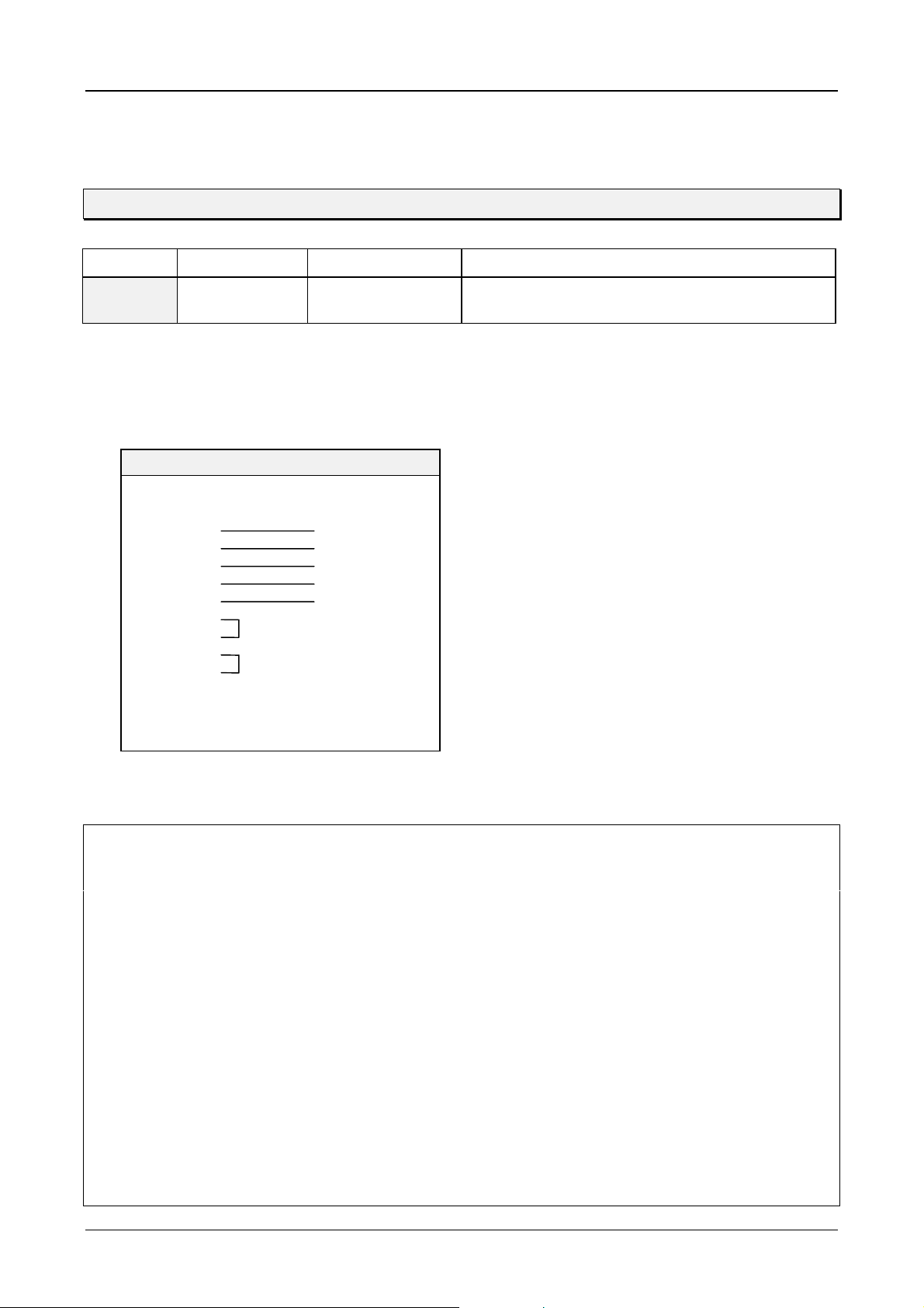
Communications Card Description ZB4-601-IF1, ZB4-609-IF1 4-21
8.4 Omron
OMRON
PLC Type Protocol PLC Port Parameters
C-/H-/K
series
DRIVER DESIGNATION (6, 1) : OMRON > CHK series
SUPPORTED DATA TYPES : HR, IR, DM
WIRING LIST
Host Link Host Link Unit 9600 baud, 7 data bits, 2 stop bit, parity even
RS 422
Signal Pin Pin Signal
TxD+ 2 1 RxD+
RxD+ 3 5 TxD+
SG 5 3 SG
TxD- 7 6 RxDRxD- 8 9 TxDDTR+ 1
DSR+ 4
DTR- 6
DSR- 9
ZB4-601/609-IF1 Host Link
(9 pole male)
(9 pole male)
NOTES
• To connect the unit you require a Host Link Unit at the PLC end. This unit must support at least the
following command codes:
“RR“,“RH,“RD“,“WR“,“WH“,“WD“ and “SC“
• These command codes are all available in command level 1 and so no special settings are required.
Addressing registers (HR, IR, DM) that are not available will initiate communication errors!
• In order to establis h active communication the station number settin g on the Host Link Unit m ust match
the addressed station.
• The physical interface of the ZB4-601/609-IF1 must be configured for RS 422 (not MP) and the
parameters on the Host Link Unit must be set as specified.
• IMPORTANT: The Link Type Selector on the Host Link Unit must be set for Multiple Link.
• During active communication the RCV and XMT LEDs on t he Host Link Unit will f licker. If only the RC V
LED flashes (very shortly), this means that the station numbers are not matching or the Link Type
Selector is set for Single Link.
• The bus terminating resistors on the first and last units must be activated. If only two units are linked, then
the resistors of both units must be switched on.
• Fit the scr een on the plug connector ho using of the ZB4-601/ 609-IF1. Refer to Omr on specifications for
how to fit the screen on the PLC.
Moeller 07/01 AWB-C2700-1347GB
 Loading...