

Page 1

Building Automation
Rückentext
SystemsIndustrial Automation
Device Description
Display PLC
MC-HPG-2x0
04/05 AWB2776-1574GB
Page 2

All brand and product names are trademarks or registered
trademarks of the owner concerned.
st
1
published 2005, edition date 04/05
© Moeller GmbH, 53105 Bonn
Author:Gerhard Fischbacher
Production: Norbert Mausolf
All rights reserved, including those of the translation.
No part of this manual may be reproduced in any form
(printed, photocopy, microfilm or any other process) or processed,
duplicated or distributed by means of electronic systems without
written permission of Moeller GmbH, Bonn.
Subject to alteration without notice.
Page 3

I
Before commencing the installation
• Disconnect the power supply of the device.
• Ensure that devices cannot be accidentally restarted.
• Verify isolation from the supply.
• Earth and short circuit.
• Cover or enclose neighbouring units that are live.
• Follow the engineering instructions (AWA) of the
device concerned.
• Only suitably qualified personnel in accordance with
EN 50110-1/-2 (VDE 0105 Part 100) may work on
this device/system.
• Before installation and before touching the device ensure
that you are free of electrostatic charge.
• The functional earth (FE) must be connected to the protective
earth (PE) or to the potential equalisation. The system installer
is responsible for implementing this connection.
• Connecting cables and signal lines should be installed so
that inductive or capacitive interference does not impair the
automation functions.
• Install automation devices and related operating elements in
such a way that they are well protected against unintentional
operation.
• Suitable safety hardware and software measures should be
implemented for the I/O interface so that a line or wire
breakage on the signal side does not result in undefined
states in the automation devices.
• Ensure a reliable electrical isolation of the low voltage for the
24 volt supply. Only use power supply units complying with
IEC 60364-4-41 (VDE 0100 Part 410) or HD 384.4.41 S2.
• Deviations of the mains voltage from the rated value must
not exceed the tolerance limits given in the specifications,
otherwise this may cause malfunction and dangerous
operation.
• Emergency stop devices complying with IEC/EN 60204-1 must
be effective in all operating modes of the automation devices.
Unlatching the emergency-stop devices must not cause restart.
• Devices that are designed for mounting in housings or control
cabinets must only be operated and controlled after they have
been installed with the housing closed. Desktop or portable
units must only be operated and controlled in enclosed
housings.
• Measures should be taken to ensure the proper restart of
programs interrupted after a voltage dip or failure. This should
not cause dangerous operating states even for a short time.
If necessary, emergency-stop devices should be implemented.
• Wherever faults in the automation system may cause
damage to persons or property, external measures must be
implemented to ensure a safe operating state in the event of
a fault or malfunction (for example, by means of separate limit
switches, mechanical interlocks etc.).
Moeller GmbH
Safety instructions
Warning!
Dangerous electrical voltage!
Page 4

II
Page 5

Device Description MC-HPG-2x0 Display PLC MC-HPG-2x0
Contents
Contents
1 Explanation of symbols............................................................................................ 7
2 Introduction ............................................................................................................... 9
3 Device versions....................................................................................................... 11
3.1 Specifications.....................................................................................................................11
3.2 Accessories........................................................................................................................12
3.3 Designing...........................................................................................................................12
4 Features ................................................................................................................... 13
5 Commissioning ....................................................................................................... 15
5.1 Overview of connections....................................................................................................15
5.2 Inserting the CompactFlash™ ...........................................................................................16
5.3 Inserting the battery ...........................................................................................................17
5.4 Connecting the power supply.............................................................................................18
5.5 Preparing the shield connections.......................................................................................19
5.6 Connecting the programming interface..............................................................................20
5.7 CAN interface.....................................................................................................................21
5.8 Connection for keyboard....................................................................................................24
5.9 Connection for ProfibusDP master (Optional)....................................................................24
5.10 Connection for COM1 serial interface (RS232) ...............................................................24
6 Operation ................................................................................................................. 25
6.1 Startup behaviour...............................................................................................................25
6.2 Shutdown behaviour ..........................................................................................................25
6.3 PLC operating states .........................................................................................................26
6.4 Changing operating mode..................................................................................................27
6.5 Startup behaviour/startup...................................................................................................28
6.6 Program transfer ................................................................................................................28
6.7 System settings..................................................................................................................29
7 Mounting instructions ............................................................................................ 31
7.1 General mounting instructions ...........................................................................................31
7.2 Mounting in the front panel ................................................................................................31
7.3 Front panel cutout..............................................................................................................32
7.4 Mechanical dimensions......................................................................................................33
7.5 External fan........................................................................................................................34
8 Notes on the touch screen ..................................................................................... 35
8.1 Basic touch screen function...............................................................................................35
8.2 Power up function test .......................................................................................................35
8.3 Cleaning and maintenance of the touch screen.................................................................35
9 Display, backlight, contrast ................................................................................... 37
9.1 Contrast .............................................................................................................................37
9.2 Backlight ............................................................................................................................37
10 Diagnostics.............................................................................................................. 37
11 Maintenance and repair .......................................................................................... 39
12 Technical data ......................................................................................................... 41
13 Disposal ................................................................................................................... 43
04/05 AWB2776-1574GB
© by Moeller GmbH
5
Page 6

MC-HPG-2x0 Display PLC Device Description MC-HPG-2x0
Contents
14 EU Conformity......................................................................................................... 43
15 Revision history ...................................................................................................... 45
16 Alphabetical index .................................................................................................. 47
04/05 AWB2776-1574GB
© by Moeller GmbH
6
Page 7
Device Description MC-HPG-2x0 Display PLC MC-HPG-2x0
Explanation of symbols
1 EXPLANATION OF SYMBOLS
Danger warnings
The following information is for your personal safety and the prevention of
damage to the device described or connected devices.
Safety instructions and warnings for the prevention of danger to the life and
health of users or service personnel, and for the prevention of damage are
highlighted in this document by the following pictograms. “Warning” and
“Information” pictograms are shown in this document.
Warnings indicate the following:
Death, serious injury or substantial material damage may occur if the
related safety measures are not implemented.
The individual “Warning” pictograms have the following meaning:
Caution! General!
An instruction to be observed in order to ensure protection
against hazards and the safe operation of the device. The
specified procedure should be observed.
Caution! Electric shock!
Persons may be exposed to dangerous voltages that occur
in electrical systems. There is a danger of electric shock if a
live part is touched.
Caution! Observe ESD measures!
Electrostatic discharge may destroy electronic components.
Information pictograms indicate the following:
Important information about the product or the relevant section of the
document, requiring the particular attention of the reader.
The “Information” pictogram has the following meaning:
Indicates important and instructional information.
04/05 AWB2776-1574GB
© by Moeller GmbH
7
Page 8

MC-HPG-2x0 Display PLC Device Description MC-HPG-2x0
Explanation of symbols
04/05 AWB2776-1574GB
© by Moeller GmbH
8
Page 9

Device Description MC-HPG-2x0 Display PLC MC-HPG-2x0
Introduction
2 INTRODUCTION
Features of the MC-HPG-2x0 devices
• PC-COMPATIBLE COMPUTER CORE
• STANDARD FIELDBUS INTERFACES
CANopen, PROFIBUS-DP (Option)
• ETHERNET ONBOARD
• EXCHANGEABLE COMPACTFLASH™
• PROGRAMMABLE TO IEC61131 (IL, LD, FBD, SFC, ST, CFC)
• INFRARED TOUCH-TECHNOLOGY
• IP65 FRONT
The MC-HPG-2x0 series display PLC combines in one device a graphical
operator panel with touch screen and a powerful compact PLC. This futureoriented device concept offers a wide range of automation and networking
options.
The PLC is programmed in compliance with the IEC61131 industrial
standard. The graphical screen masks are designed effectively and simply
using the visualization tool EPAM and EXCEL. This makes the display PLC
a universal device for automation applications.
The integration of third-party systems (I/Os, drives etc.) via standard fieldbus
interfaces (CANopen) and their integration in the overall system offers
access to a wide range of process optimized peripheral components.
Thanks to the integrated Ethernet interface the MC-HPG-2x0 series display
PLCs have the capabilities for Web applications.
Application range
The MC-HPG-2x0 series display PLC is designed for controlling, operating
and monitoring machines and plants. The integrated infra-red touch
technology ensures fast and simple operation. The rugged and compact
design allows the implementation of applications that were previously
impossible due to the space and cost requirements involved.
The high degree of protection (front IP65) and the omission of any moving
parts (hard disks, fans) makes the devices ideal for robust use in rugged
industrial environments directly at the machine.
The devices can be installed in control panels or control desks without any
problem.
This device description is a reference for the technical data, installation,
terminals, commissioning, operation, and maintenance of all MC-HPG-2x0
versions. The illustrations in this document are for the 5.7” device version
( Section 3), unless otherwise stated. The designation and function of the
connections and signals are the same for all versions.
04/05 AWB2776-1574GB
© by Moeller GmbH
9
Page 10

MC-HPG-2x0 Display PLC Device Description MC-HPG-2x0
Introduction
04/05 AWB2776-1574GB
© by Moeller GmbH
10
Page 11
Device Description MC-HPG-2x0 Display PLC MC-HPG-2x0
Device versions
3 DEVICE VERSIONS
The term MC-HPG-2x0 stands for the following versions.
MC-HPG-2x0 Device types
Type designation Display Fieldbus Resolution Power supply
MC-HPG-210
5.7“ STN mono CAN ¼-VGA (320 x 240) 24 VDC
MC-HPG-230
5.7“ STN color CAN ¼-VGA (320 x 240) 24 VDC
MC-HPG-230-DP
5.7“ STN color CAN
ProfibusDP master
¼-VGA (320 x 240) 24 VDC
The following front plate versions are available:
Standard plastic front with Moeller membrane seal
Front plate
type
3.1 S
PECIFICATIONS
MC-HPG-210
Art.Nr : MC-HPG-210
PLC compactline Touch mono 5.7”
5.7” STN mono, SC400 66MHz, 16MB DRAM, 32kB NVSRAM, CF-Interface, IR-Touch
Interface: CAN, 1 x RS232, Ethernet 10MB
MC-HPG-230
Art.nr : MC-HPG-230
PLC compactline Touch color 5.7”
5.7” STN color, SC400 66MHz, 16MB DRAM, 32kB NVSRAM, CF-Interface, IR-Touch
Interface: CAN, 1 x RS232, Ethernet 10MB
MC-HPG-230-DP
Art.nr : MC-HPG-230-DP
PLC compactline Touch color 5.7”
5.7” STN color, SC400 66MHz, 16MB DRAM, 32kB NVSRAM, CF-Interface, IR-Touch
Interface: CAN, ProfibusDP-Master , 1 x RS232, Ethernet 10MB
04/05 AWB2776-1574GB
© by Moeller GmbH
11
Page 12
MC-HPG-2x0 Display PLC Device Description MC-HPG-2x0
Device versions
3.2 ACCESSORIES
Battery
Order No.: MC-ACP-BAT01
Battery
Spare battery (Type
Section12)
Programming cable
Order No.: MC-ACP-CAPC01
Programming cabel
Programming cable RS232 Null modem (serial connection)
3.3 DESIGNING
Moeller XSoft
(on CD)
XSoft CD
Consisting of:
- XSoft -> IEC61131 software
- Documentation in PDF format
04/05 AWB2776-1574GB
© by Moeller GmbH
12
Page 13
Device Description MC-HPG-2x0 Display PLC MC-HPG-2x0
Features
4 FEATURES
Feature Comment
Display
Graphic Size 5.7”
Type STN 16 greyscales/16 colors
Resolution Pixels 320 x 240
Touch
Infra-red touch Resolutio
n
45 x 33
PLC
Languages IEC61131 IL, LD, FBD, SFC, ST, CFC
Debug options Yes Online change, breakpoint, trace, flow control
PLC program KByte 512
PLC data KByte 256
Retain data KByte Max. 32 (Default: 16KB)
Multi-tasking Yes
Network variables Yes Ethernet or CAN
Cycle time/k instructions ms Normally 0.8ms
Real-time clock Yes Battery-backed
Visualization
Memory for visualization MByte 2
Messages Number Normally 2000
Alarms Number Max. 1008
Alarm history Number Max. 512
Process variables Number Normally 1000
Process screen pages Number Normally 300
Online languages Number Normally 5
Character languages Yes e.g. Chinese, Japanese,...
Recipes Yes Can be edited in ASCII text format
Password Yes Normally 10 levels
Communication
COM1 (RS232) kBit/s Max. 38.4KB
CAN (CANopen) kBit/s CAN master, max. 500 Default: 125
Ethernet MBit/s 10
ProfibusDP MBit/s Max. 12 (Ord. No.: 85 24 000110)
Remote maintenance Yes With external modem serial or via Ethernet (e.g.
with ISDN router)
Exchangeable
memory
CompactFlash™ MByte Up to 64 MB
Software update via
CompactFlash™
Yes PLC project, visualization, runtime system
The number of designable process screens, messages, languages etc. is
restricted by the memory available for visualization. The memory required
per image greatly depends on the application concerned, and is mainly
determined by the size and number of images (PCX) used. 50 KBytes and
more may be required for showing an image with a resolution of 320*240
pixels. If an image of this size is designed on each screen page, the number
of possible screen pages would be less than 40.
These specifications are based on typical sizes that are used in real
projects. With sufficient memory, these values can be exceeded. However,
this will result in longer reaction times and screen change times. (see also
Easy PageMachine (EPAM) manual)
04/05 AWB2776-1574GB
© by Moeller GmbH
13
Page 14

MC-HPG-2x0 Display PLC Device Description MC-HPG-2x0
Features
In the system the PLC program has priority over the
visualization. Therefore the PLC program should not
take up all the CPU time otherwise operation and
visualization will be impossible or very slow.
Delays in the visualization may occur during file
transfers (such as project downloads, FTP, WEB
servers), or during communication with the
development system (e.g. PLC debugging) as the
visualization has the lower priority.
CompactFlash™ memory media are NOT suitable for
cyclical data logging due to the limited number of write
cycles (normally 100,000).
04/05 AWB2776-1574GB
© by Moeller GmbH
14
Page 15
Device Description MC-HPG-2x0 Display PLC MC-HPG-2x0
Commissioning
5 COMMISSIONING
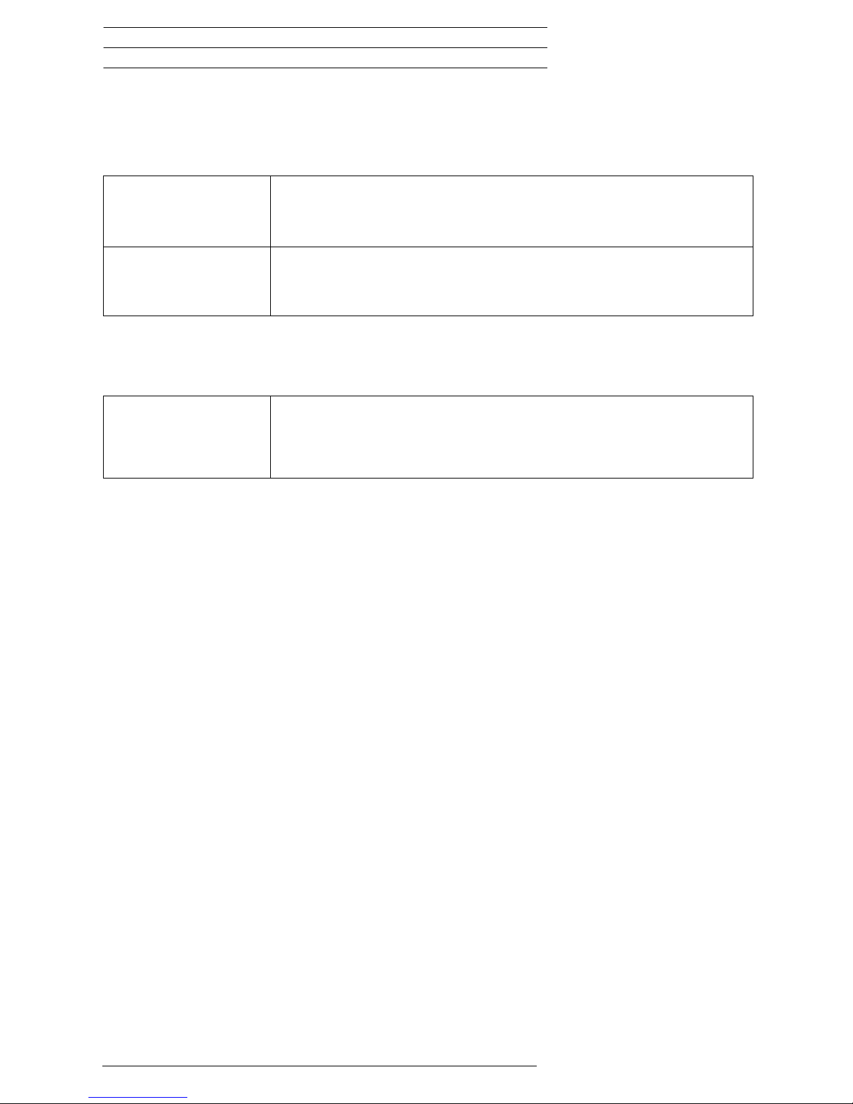
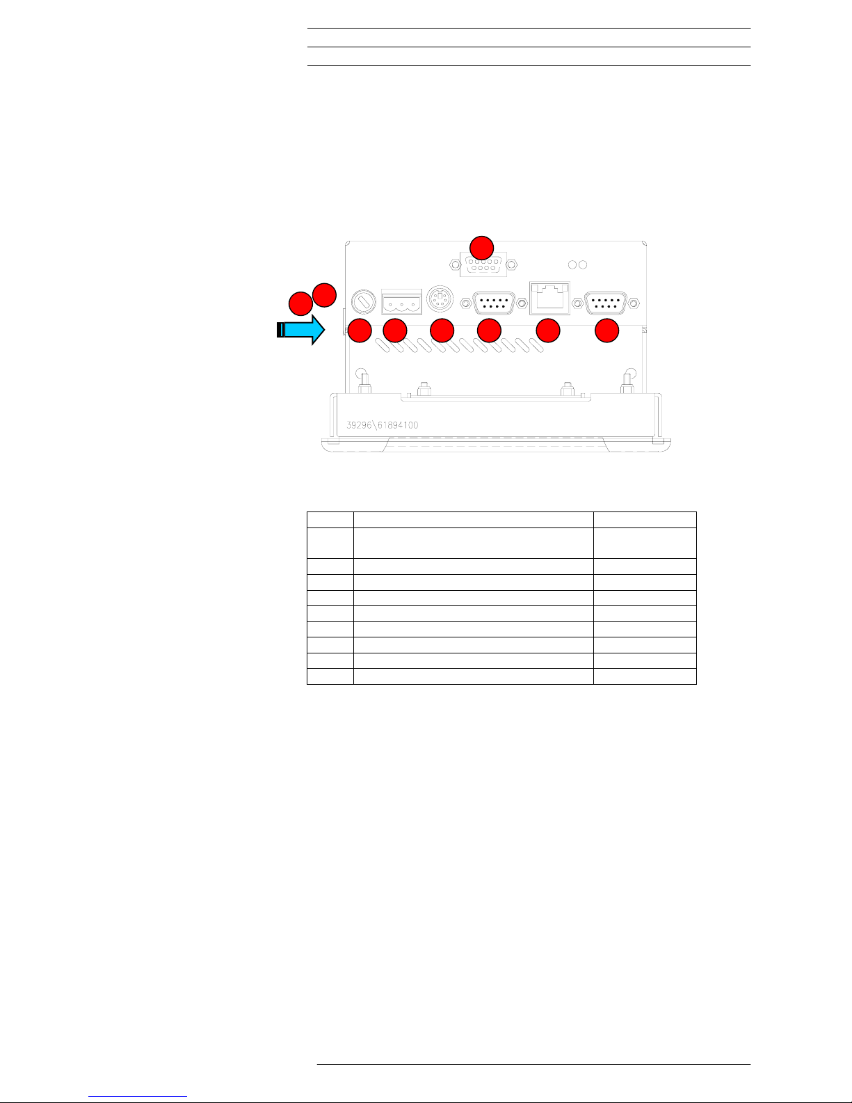
5.1 OVERVIEW OF CONNECTIONS
9
2
1
3 4 5 6 7 8
No. Element Description
1 Battery for retain PLC data and real-
time clock
Page 17
2 CompactFlash™ Interface Page 16
3 Fuse Page 18
4 24VDC power supply Page 18
5 PS2 keyboard Page 24
6 CAN connector 9-pole Sub-D, male Page 21
7 RJ45 Ethernet Page 20
8 RS232 COM1 Page 24
9 ProfibusDP/SIO/AUX (Option) Page 24
04/05 AWB2776-1574GB
© by Moeller GmbH
15
Page 16

MC-HPG-2x0 Display PLC Device Description MC-HPG-2x0
Commissioning
5.2 INSERTING THE COMPACTFLASH™
The MC-HPG-2x0 series devices use a CompactFlash™ card for storing the
runtime system, the application or data (e.g. recipes).
A CompactFlash™ card with the pre-installed MC-HPG-2x0 runtime system
is already inserted when delivered.
To change the CompactFlash™, undo the cover of the CompactFlash™
interface and insert the appropriate MC-HPG-2x0 runtime system. The cover
must be refitted and fastened.
The CompactFlash™ must only be fitted or removed
with the device power supply switched off.
The device cannot run without a CompactFlash™ card.
Correct functioning of the device can only be ensured
by using CompactFlash™ cards obtained from the
original accessories.
04/05 AWB2776-1574GB
© by Moeller GmbH
16
Page 17

Device Description MC-HPG-2x0 Display PLC MC-HPG-2x0
Commissioning
5.3 INSERTING THE BATTERY
The battery supplied (Ord. no. MC-ACP-BAT01) is used for backing up the
real-time clock and the retain PLC data. The battery is already inserted
when delivered. It can be replaced in the following way:
1. Connect the device to power supply at least 10 minutes
2. Unplug the power supply (retain data will be stored at least 2 minutes)
3. Replace battery
04/05 AWB2776-1574GB
© by Moeller GmbH
17
Page 18

MC-HPG-2x0 Display PLC Device Description MC-HPG-2x0
Commissioning
5.4 CONNECTING THE POWER SUPPLY
The MC-HPG-2x0 device belongs to protection class 3. The system power
supply must be provided with a 24VDC SELV voltage ( Section 12). The
power supply is not isolated. The 0V connection is directly connected to the
housing potential. The device is protected with a 1.6 A slow fuse (note
disconnection capacity Section 12). A reverse polarity protective device is
used to protect the device in the event of reversed poles. Operation,
however, is only possible if the connection was made correctly.
Connections for the MC-HPG-2x0 must comply with specific, local
regulations.
The connection must be made as follows:
1. The cross-section of the power supply cable must be at least 0.75 mm²
and a maximum of 2.5 mm².
2. A flexible lead or wire can be used for the connection.
3. The current consumption ( Section 12) must be taken into account
when implementing the power supply. The functional earth is not
compulsory for operation. The GND connection is directly connected to
the housing potential
The plug connector (socket connector screw with terminals) is supplied with
the device for connection.
Connector assignment
+24VDC GND 0V
(plug connector: Phönix MSTB 2.5/3-ST-5.08
Phönix Ord. No. 1757022)
Designation Function
+24 VDC +24VDC power supply
GND Functional ground
0V 0V power supply
04/05 AWB2776-1574GB
© by Moeller GmbH
18
Page 19

Device Description MC-HPG-2x0 Display PLC MC-HPG-2x0
Commissioning
5.5 PREPARING THE SHIELD CONNECTIONS
The preparation of the data and signal cables is an important factor for the
electromagnetic compatibility (EMC) of the MC-HPG-2x0, both in terms of
interference immunity and emission.
The RS232 interface and CAN interface are connected via D-Subminiature
plug connectors in accordance with DIN 41652. Only use metal or
metallised connector casings with a cable clamp for strain relief fastened or
clamped on the connector. The clamping of the cable shield ensures an
optimum contact area and a low impedance connection with the connector
casing of the MC-HPG-2x0 display PLC.
The following procedure is recommended for making the low-impedance
connection for the cable shield:
1. Strip the cable.
2. Shorten the exposed shield braid by approx. 3 cm.
3. Turn back the braid over the cable sheath.
4. Use a heat shrinkable tubing or rubber grommet to cover the exposed
cable sheath with the folded back shield braid so that 5 to 8 mm of
exposed cable shield is left at the sheath end and is cleanly covered at
the back.
5. Fit the connector
6. The cable is then fastened at the exposed shield braid and the cable
sheath below it directly underneath the cable clamp strap of the
connector casing.
Metal or metallised
D-subminiature connector
Metallic
connector shroud
Fastening
screws
connector casing
Heat shrinkable
tubing for covering
the shield braid
Shield braid pulled
back over the
cable sheath
Strap for cable clamp
and contacting of the
cable shield with the
connector casing
Connection work should be carried out with special care
in order to ensure trouble-free operation.
The EMC values stated in the technical data can only be
guaranteed if the cables are prepared according to the
following specifications.
04/05 AWB2776-1574GB
© by Moeller GmbH
19
Page 20

MC-HPG-2x0 Display PLC Device Description MC-HPG-2x0
Commissioning
5.6 CONNECTING THE PROGRAMMING INTERFACE
The programming is carried out via the standard Ethernet interface (RJ45).
The connection to the programming PC is implemented using a standard
Ethernet cable (1:1) via a hub or directly using a crosslink cable. The cables
are also available as an accessory ( Section 0).
Before the device is connected to the Ethernet network, the IP address of
the device and the programming PC must be set ( Section 6.7).
IP addresses can be obtained from your system or
network administrator. IP addresses must be uniquely
defined in an Ethernet network. The IP address of all
networks and of the programming PC must be in the
same subnetwork (e.g. 192.168.0.xxx).
Connector assignment
RJ45
connector
Pin No. Signal Description
1 TXD
2 TXD+
3 RXD+
4 -
5 -
6 RXD
Socket, 8pole
7 -
RJ45
8 -
1
2
3
4
5
6
7
8
Alternatively, programming can also be implemented via the RS232 serial
interface on COM1. This interface is not isolated. The GND connection is
implemented directly on the housing potential ( Section 12).
Cables connected to the programming interface (Ethernet or serial) must be
laid separately from the low-voltage cables.
A detailed description of the project download is
provided in the “XSoft” system description or in the
appropriate software documentation.
04/05 AWB2776-1574GB
© by Moeller GmbH
20
Page 21

Device Description MC-HPG-2x0 Display PLC MC-HPG-2x0
Commissioning
5.7 CAN INTERFACE
The communication interface is defined in accordance with the CiA CAN
Specification V2.0 part B. The fully-integrated CAN unit supports the sending
and receiving of frames with an 11-bit identifier. The type of configuration
selected depends on the software protocol. The baud rate can be selected in
a wide range, and only the standard CiA baud rates are implemented. The
MC-HPG-2x0 is the master on the CAN bus.
CAN connector
Sub-D 9 Pole male
Connect
or
Pin No. Assignme
nt
Function
1 -
2 CAN
LOW
Negative data signal
3 GND Signal Ground (ground potential)
4 -
5 -
6 GND Signal Ground (ground potential)
7 CAN
HIGH
Positive data signal
8 -
9 -
Case Case Cable shield
5
9
4
8
3
7
2
6
1
The CAN interface is isolated.
The max. baud rate is 500kBit/s.
The terminating resistor must be implemented externally,
e.g. in the connector, and is not part of the device.
The CAN connector is not provided with a supply for
third-party devices.
A detailed description of the wiring is provided in the
“XSoft” system description
04/05 AWB2776-1574GB
© by Moeller GmbH
21
Page 22

MC-HPG-2x0 Display PLC Device Description MC-HPG-2x0
Commissioning
Wiring instructions
The stations on the bus system are connected via fieldbus lines complying
with ISO 11898. The cables must accordingly have the following electrical
characteristics:
Parameter Abbreviation Unit Value Value Value Note
min. nom. max.
Impedance Z Ω 108 120 132 Measured between two
signal lines
Specific
resistance
mΩ/m 70 For the receiver
module, the differential
voltage on the bus
cable depends on cable
resistance between it
and the sender
Cable delay ns/m 5 The mininum delay
between to points on
the bus is 0. The
maximum delay is
determined by the bit
timing and the delays of
the sender and receiver
circuits
The figure shows the minimum wiring with shielding between two bus
stations with the Sub-D connector as an example. A bus terminating resistor
(120 Ohm between Pin 2 and Pin 7 of the Sub-D connector) must be
connected at the beginning and the end of each CAN bus. Do not swap
around the two signal wires!
Protective ground
Interface 1 Interface 2
Shield
Protective ground
04/05 AWB2776-1574GB
© by Moeller GmbH
22
Page 23

Device Description MC-HPG-2x0 Display PLC MC-HPG-2x0
Commissioning
bus terminating resistor
Station n
Station 1
Inside: twisted pair cable Shield
Pin 3 and 6 (CAN_GND) are both connected internally with the CAN
Ground. Pins 4, 5 and 8 must not be connected! The CAN bus driver is fed
internally.
Baud rate and cable lengths
Baud rate Max. length
20kBit/sec 2500m
25kBit/sec 2000m
50kBit/sec 1000m
100kBit/sec 650m
125kBit/sec 500m
250kBit/sec 250m
500kBit/sec 100m
04/05 AWB2776-1574GB
© by Moeller GmbH
23
Page 24

MC-HPG-2x0 Display PLC Device Description MC-HPG-2x0
Commissioning
5.8 CONNECTION FOR KEYBOARD
The keyboard terminal is PC-compatible (PS2) and is only provided for
testing and service tasks.
Connector
Pin No. Signal Description
1 KBDATA
2 -
3 KBGND
4 KBVCC Fused
5 KBGND
6 -
65
43
21
7
8
9
Socket 6pole
MiniDIN
5.9 CONNECTION FOR PROFIBUSDP MASTER (OPTIONAL)
The ProfibusDP master interface is only available in the version
Ord No.: MC-HPG-230-DP
Socket
Pin No. Signal Description
1 -
2 -
3 RXD/TXD+
4 -
5 GND
6 +5V
Fused, not isolated
7 -
Socket 9pole
8 RXD/TXD-
SubD
9 -
5
9
4
8
3
7
2
6
1
5.10 CONNECTION FOR COM1 SERIAL INTERFACE (RS232)
Connector
Pin No. Signal Description
1 DCD
2 RXD
3 TXD
4 DTR
5 GND
6 DSR
7 RTS
Connector
9pole
8 CTS
SubD
9 RI
5
9
4
8
3
7
2
6
1
04/05 AWB2776-1574GB
© by Moeller GmbH
24
Page 25

Device Description MC-HPG-2x0 Display PLC MC-HPG-2x0
Operation
6 OPERATION
6.1 STARTUP BEHAVIOUR
After power on, the MC-HPG-2x0 carries out a system test. The PLC does
not switch to Run or Stop until no hardware errors have been found. The
system test includes the following:
• Memory test
• Flash disk test
Start messages
Version display of firmware:
Module name Version Size
VxWorks V 1.4.0005 974872
ethercfg.out V 1.1 2192
plcvxw.out 350055
cstitf.out V 1.2.0001 12082
cstcan.out V 2.3.0003 211286
cstepam.out V 1.1 5177
epam.out V 3.0.0168 824847
restore.out V 1.0.0001 5597
drvarti.out V 1.0.0015 99292
chttpd.out V 1.0.0007 17307
6.2 SHUTDOWN BEHAVIOUR
Voltage dips of <= 10ms at 24V ( Section 12) are bridged by the power
supply unit. Longer voltage dips will cause the PLC to be reset
automatically.
Writing data to the CompactFlash™ during a power
supply failure will cause the data to be lost!
The EPAM visualization software therefore makes a
copy of the file in the directory C:\BACKUP before every
write operation. These files are restored if necessary at
the start.
04/05 AWB2776-1574GB
© by Moeller GmbH
25
Page 26

MC-HPG-2x0 Display PLC Device Description MC-HPG-2x0
Operation
6.3 PLC OPERATING STATES
Power on
In Power on status, there is no user program in the PLC. In this status it is
possible to load a program onto the PLC. The Power on status is indicated
in the programming software.
Stop
The Stop operating status has the following features:
• A user program is stored on the PLC
• The user program is not running
The Stop status is selected:
• After power on, if the entry Startup=STOP has been made in the
PLC.INI file ( Section 6.7)
• After power on, if the entry Startup=AUTO has been made in the
PLC.INI file ( Section 6.7), and the PLC was in Stop status at the
last online access via the programming software
• Via the programming software in the PC
• After the cycle time is exceeded
Run
In RUN status, the user program is processed cyclically.
The RUN operating status is selected:
• After power on, if the entry Startup=WARM has been made in the
PLC.INI file ( Section 6.7) (Default)
• Via the programming software in the PC
• After power on, if the entry Startup=AUTO has been made in the
PLC.INI file ( Section 6.7), and the PLC was in Run status at the
last online access via the programming software
System Fault SF
The following system faults can occur ( Section 10):
• Hardware fault
• Firmware system faults
04/05 AWB2776-1574GB
© by Moeller GmbH
26
Page 27

Device Description MC-HPG-2x0 Display PLC MC-HPG-2x0
Operation
6.4 CHANGING OPERATING MODE
The operating mode of the MC-HPG-2x0 devices is changed via the
PLC.INI configuration file in the C:\MCONTROL directory on the
CompactFlash™ or via the programming software.
PLC.INI configuration file:
The following entries can be made in the [BOOT] section:
Startup=WARM ...PLC starts in RUN mode (Default)
Startup=STOP ...PLC starts in STOP mode
Startup=AUTO ...PLC startup behaviour can be
controlled by the programming software. The PLC
starts up in the status set at the last online access.
Programming software:
Reset
This command resets all variables to the value with which they were
initialized apart from the retain variables (RETAIN, PERSISTENT).
Variables not explicitly assigned an initialization value are set to the
standard initial values (integers for example to 0). XSoft outputs an
appropriate safety prompt before all variables are overwritten. This also
happens when there is a power failure or when the PLC is switched off and
on again (warm start).
Use the command ‘Online’, ‘Start’ to restart the PLC and resume program
processing.
Reset Cold
This command resets all variables to their initial values regardless of
whether they are RETAIN variables or not. Only persistent variables retain
the value they had before the reset.
Reset Original
This command resets all variables including retain variables (RETAIN and
PERSISTENT) to their initial values and deletes the user program on the
PLC. The PLC is reset to its basic setting.
Start
The command starts the running of the user program in the PLC.
The command can be executed directly after the commands ‘Online’, ‘Load’
or after the user program was stopped in the PLC via the commands
‘Online’, ‘Stop’, or if the user program is at a break point, or after the
commands 'Online', 'Single Cycle'.
A detailed description of the online functions is also provided the XSoft
manual.
04/05 AWB2776-1574GB
© by Moeller GmbH
27
Page 28

MC-HPG-2x0 Display PLC Device Description MC-HPG-2x0
Operation
6.5 STARTUP BEHAVIOUR/STARTUP
After power on, the user program is loaded from the CompactFlash™ into
the RAM and the PLC is started.
Procedure
:
Power on
PLC-
Programm
present
?
Battery
o.k.
?
Reset-cold
Start (PLC.INI)
PLC- Status:
„Run“
PLC- Status:
„Stop“
PLC- Status:
„System Fault“
PLC-Status:
„Power on“
Startup=WARM
(Default)
?
Startup=STOP
?
Hardware-
o.k.
?
No
No
No
No
6.6 PROGRAM TRANSFER
If the user program was compiled error-free on the programming device
(PC), it can be loaded into the working memory of the MC-HPG-2x0 and
then started.
PC PLC:
When logging on to the PLC from the PC, the program in the PLC is
compared to the program in the PC. If they are not the same, a prompt will
ask whether the program is to be overwritten. If this prompt is confirmed, the
PLC switches to Stop status and the new program is loaded into the working
memory. (Program transfer/Online Change see also the XSoft manual).
PC PLC and CompactFlash™:
The user program is saved on the CompactFlash™ by generating a boot
project.
04/05 AWB2776-1574GB
© by Moeller GmbH
28
Page 29

Device Description MC-HPG-2x0 Display PLC MC-HPG-2x0
Operation
6.7 SYSTEM SETTINGS
The MC-HPG-2x0 devices are supplied with a startup application that
allows the following system settings:
• IP address setting (Default: 192.168.0.99)
• Gateway address setting
• Date and time setting
• Contrast and backlight setting
These system settings must be made in the visualization application of the
user. The start application is supplied with EPAM for this purpose, and can
be used as a basis for user applications.
After a new project is downloaded, the start application is no longer
available. The system settings can therefore only be carried out if this is
implemented in the application.
The system settings must be implemented in the
visualization application. After a new project is
downloaded, the start application is no longer available!
The system settings are saved in the CONFIG.INI file.
The subnetwork mask is defined automatically on the basis of the class of
the IP address. For the default IP address the subnetwork mask is:
255.255.255.0
PLC.INI configuration file
The PLC.INI file is supplied in the following state:
#**************************************************************************************
# PLC.INI
#
# Note: Preserving the original configuration is recommended
#
#**************************************************************************************
[BOOT]
Startup=WARM # Startup mode of PLC boot project: WARM (default) / STOP / AUTO
# Note: Startup mode AUTO preserves the PLC mode of the last online session
[CONFIG]
RetainMode=CST_RETAIN_CYCLE # Retain memory saved at end of PLC cycle (CST_RETAIN_CYCLE=default)
RetainSize=0x8000
RetainAddress=0xD8000
CAN
CANbaudrate=500 # Startup CAN baud rate (no used with CoDeSys CAN Configurator)
CANinpQueueSize=16
[EPAM]
PrioEPAM=254 # Priority of EPAM task (254=default)
PrioTOUCH=253 # Priority of touch task (should be lower than PrioEPAM) (253=default)
DelayTicksEPAM=1 # Number of system ticks that EPAM suspends at the end of the EPAM loop (1=default)
Only the [BOOT] entry can be changed by the user in
the PLC.INI configuration file. All other settings must
not be changed.
04/05 AWB2776-1574GB
© by Moeller GmbH
29
Page 30

MC-HPG-2x0 Display PLC Device Description MC-HPG-2x0
Operation
04/05 AWB2776-1574GB
© by Moeller GmbH
30
Page 31

Device Description MC-HPG-2x0 Display PLC MC-HPG-2x0
Mounting instructions
7 MOUNTING INSTRUCTIONS
7.1 GENERAL MOUNTING INSTRUCTIONS
All MC-HPG-2x0 series devices are mounted from the front, i.e. in a control
panel. They are fastened from the rear with the supplied fixing frame and 4
securing nuts.
All MC-HPG-2x0 series devices can be operated up to a maximum ambient
temperature of 45°C ( Section12 ). The ambient temperature stated
applies to the area in the direct vicinity of the lower connectors, if the device
is mounted vertically with unimpeded air convection and a maximum
operating height of 2000m above sea level. The cooling slots must always
be free in order to ensure the proper cooling of the system.
The device can be mounted in an enclosure if the ambient temperature is
taken into consideration. Provide a wall clearance of at least 50 mm on all
sides of the housing, so that sufficient air circulation is ensured. A minimum
clearance of 75 mm from active elements such as load current supply,
transformers etc. must be ensured.
Avoid the exposure of the flat screen to direct sunlight. The radiation from
the sun (UV component) reduces the lifespan of the LCD display.
The following must be ensured in order to prevent the
device from overheating during operation:
- The cooling slots must always be free in order to
ensure the proper cooling of the system.
- Avoid the exposure of the flat screen to direct
sunlight.
- The mounting angle must not exceed ± 35° from
the vertical
If these conditions cannot be met, the mounting of an
external fan is recommended ( Section 7.5)
7.2 MOUNTING IN THE FRONT PANEL
1. Push the MC-HPG-2x0 from the front into the cutout ( Section 7.3) of
the front panel.
2. The front seal must be level and evenly positioned between the front
plate and the front panel.
3. Centering the device in the cutout
4. Secure the device from the rear with the supplied fixing frame. For this
use the 4 securing nuts which should be tightened evenly from the rear
until the front frame is flush with the front panel all round.
Ensure that the seal is fitted correctly on the front panel.
Avoid tightening torques of greater than 0.3 Nm as this
could otherwise damage the device.
The thickness of the front plate must not exceed 5 mm.
04/05 AWB2776-1574GB
© by Moeller GmbH
31
Page 32

MC-HPG-2x0 Display PLC Device Description MC-HPG-2x0
Mounting instructions
7.3 FRONT PANEL CUTOUT
The device requires a mounting cutout of WxH:
198 +0/-1 mm x 142 +0/-1 mm
The thickness of the front panel must not exceed 5 mm.
04/05 AWB2776-1574GB
© by Moeller GmbH
32
Page 33

Device Description MC-HPG-2x0 Display PLC MC-HPG-2x0
Mounting instructions
7.4 MECHANICAL DIMENSIONS
04/05 AWB2776-1574GB
© by Moeller GmbH
33
Page 34

MC-HPG-2x0 Display PLC Device Description MC-HPG-2x0
Mounting instructions
7.5 EXTERNAL FAN
The MC-HPG-2x0 series devices are prepared for the mounting of an
external fan.
Order designations
Fan Manufacturer Papst
Type Axial fan, 24V, 40x40x20mm
Order No. 414
CageClamp connector
Manufacturer WAGO-CONTACT
Type Male connector 2 pole
Ord. No. 231-632/018-000
Screws
Type Cylinder head screw M3x22
WAGO-Klemme
WAGO clamp
231-632/018-000
2x Zylinderschraube
2x cyl. head screw
M3x22
PAPST Ventilator
Typ 414 24VDC
The fan and the WAGO clamp connector can be
mounted externally without having to open the housing.
04/05 AWB2776-1574GB
© by Moeller GmbH
34
Page 35

Device Description MC-HPG-2x0 Display PLC MC-HPG-2x0
Notes on the touch screen
8 NOTES ON THE TOUCH SCREEN
8.1 BASIC TOUCH SCREEN FUNCTION
The touch screen operates on the active light matrix principle in the infrared range. Interrupting this light matrix at any point will initiate an operation
if a touch activated screen element was touched (e.g. a button).
A timeout is initiated if the light matrix is interrupted for longer than approx.
15s. The touch panel then switches to the “non-actuated” state, and further
operations cannot be initiated until the initial touch actuation has stopped
(e.g. button released) or the touch is actuated again. Several simultaneous
touch actuations at different points cannot be evaluated.
8.2 POWER UP FUNCTION TEST
The MC-HPG-2x0 carries out a function test of the touch screen with each
power up of the device. All IR channels are tested during this stage. Faulty
IR channels are indicated graphically and displayed on screen with an error
message. The failure of IR channels is normally due to severe
contamination of the IR transparent plastic frame which consequently has to
be cleaned ( Section 8.3). The optical elements of the light matrix are
located behind the IR transparent plastic frame in the front of the device.
IR channels that are continuously interrupted will be detected by the Touch
Controller after a timeout of approx. 15s and no longer included in the
evaluation. In extreme cases, this may mean that individual zones cannot
be touch activated.
Do not touch the screen whilst the system is being
started up, and wait till your application has started.
During the startup the touch screen carries out a
function test.
8.3 CLEANING AND MAINTENANCE OF THE TOUCH SCREEN
For operation ensure that the signal levels of the channels are not so
severely reduced or interrupted due to excessive contamination through dirt
( Section 8.1).
Clean the inside of the plastic frame of the device regularly ( Section 10)
with a damp soft cloth. Ensure that the surface is not scratched or scoured,
especially when removing hard deposits and abrasive dust.
Cleaning should only be carried out with the device switched off! This
will ensure that any touching of the screen will not accidentally initiate
functions.
Do not expose the front of the device to solvents which may corrode and
loosen the plastic frame (frame material: Makrolon 2805, Manufacturer:
Bayer AG).
04/05 AWB2776-1574GB
© by Moeller GmbH
35
Page 36

MC-HPG-2x0 Display PLC Device Description MC-HPG-2x0
Notes on the touch screen
04/05 AWB2776-1574GB
© by Moeller GmbH
36
Page 37

Device Description MC-HPG-2x0 Display PLC MC-HPG-2x0
Display, backlight, contrast
9 DISPLAY, BACKLIGHT, CONTRAST
9.1 CONTRAST
The contrast voltage is temperature-compensated and can be adjusted in
the EPAM visualization software.
9.2 BACKLIGHT
The backlight has three settings (0, 50 and 100%) which can be selected in
the EPAM visualization software.
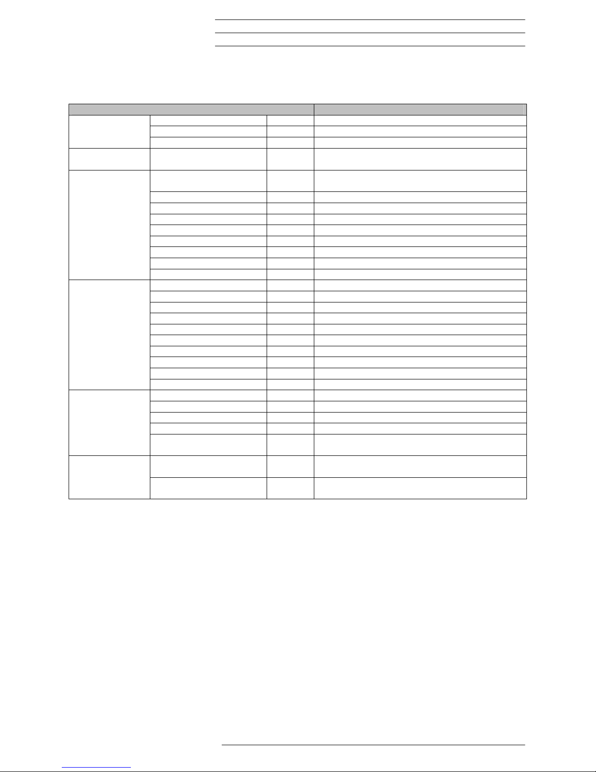
10 DIAGNOSTICS
The following optical and acoustic diagnostic options are available:
Symptom Possible cause and solution
Signal on power on - Acoustic signal:
- 2x short
Touch controller OK
- low-low-high
Battery flat, BIOS has changed or rejected a setting
Device does not start,
screen dark or error
messages during startup
- - Check power supply/fuse faulty (+5V LED not lit)
- Hard disk controller 1 failure
CompactFlash with Runtime System MC-HPG-2x0 not inserted (
Section 5.2).
Date/time incorrect Insert or replace battery ( Section 5.3)
Screen dark or light Backlight/contrast incorrectly set
Reload EPAM project with Delete INI Files option
Touch not functioning - - Hardware faulty (no acoustic signal after power on)
- Too many IR channels interrupted Clean touch
Ethernet connection faulty - - Incorrect Ethernet cable fitted (crosslink/direct).
The LINK LED is lit when the connection is correct
The ACT LED is lit (flashing during transfer) with a correct data transfer
- Incorrect/invalid IP address set
The current IP address is shown during startup at the bottom right of the
screen
Refer to the XSoft engineering software documentation
for other diagnostics options.
04/05 AWB2776-1574GB
© by Moeller GmbH
37
Page 38

MC-HPG-2x0 Display PLC Device Description MC-HPG-2x0
Display, backlight, contrast
04/05 AWB2776-1574GB
© by Moeller GmbH
38
Page 39

Device Description MC-HPG-2x0 Display PLC MC-HPG-2x0
Maintenance and repair
11 MAINTENANCE AND REPAIR
Cleaning the screen
For trouble-free operation of the IR touch screen, clean the inner section of
the device front (front glass and IR frame) regularly ( Section 8.3).
Battery
The battery is used for backing up the real-time clock and the retain PLC
data. The battery should be changed every 3 years in order to prevent any
data loss.
Procedure for changing the battery
1. Switch on the device for at least 10 minutes
2. Then switch off the device and change the battery quickly
(the data is retained for at least 2 minutes)
The real-time clock must be reset after the battery is
changed.
Repairs
Repairs to the MC-HPG-2x0 should only be carried out by the manufacturer
or Moeller GmbH repair centers. In this case, please contact your local MCControl dealer or the Technical Support at Moeller GmbH. (manufacturer's
address Section 14)
No liability is accepted for any modifications made to the device that are not
described in this document.
Transport
Only the original packaging must be used for transporting the device.
04/05 AWB2776-1574GB
© by Moeller GmbH
39
Page 40

MC-HPG-2x0 Display PLC Device Description MC-HPG-2x0
Maintenance and repair
04/05 AWB2776-1574GB
© by Moeller GmbH
40
Page 41

Device Description MC-HPG-2x0 Display PLC MC-HPG-2x0
Technical data
12 TECHNICAL DATA
Display
Technology
5.7” passive STN LCD
Resolution 320 x 240 pixels (1/4 VGA)
Number of colors 16 greyscales/16 colors
Display area 118 mm x 89 mm
Backlight 1x CCFL, dimmable via software
Contrast Temperature-compensated, adjustable via software
Front plate Safety glass, non-reflective
Operation
Type Infra-red touch
Resolution 45 x 33
Ambient
conditions
Operating climate 0...45°C, 10...90% rel. air humidity, non-condensing
Storage climate -20...60°C, 10...90% rel. air humidity, non-condensing
EMC interference immunity EN 61000-6-2
Emission EN 50081-2
Degree of
protection
Front IP 65 (NEMA 12), after EN 60529
Rear IP 20
Weight
Approx. 1.6 kg
Dimensions
W x H x D 212 x 156 x 89.2 mm
Cutout 198 x 142 mm (+0/-1mm)
System supply
Rated voltage 24 VDC SELV, safety extra low voltage
Voltage range 24 VDC to DIN 19240
20.4...28.8 VDC effective, absolute value with ripple 18.5...30.2 VDC
35.0 VDC for a duration of < 100ms
Voltage dips 10 ms to EN61000-6-2
Protection against reverse
polarity
Yes
Fuse protection Yes
Potential isolation No
The 0V connection is directly connected to the housing potential (GND)
Current consumption Normally 350mA/24VDC
Power consumption Normally 8.4 W/24VDC
Battery backup
Battery type 3V / 950mAh Lithium, RENATA CR2477N
Data retention Normally 5 years
Real-time clock
Counters Seconds, minutes, hour, day, month, year
Leap year change Automatic
DST change Manual via the software
Fuse protection
Fuse 1.6 A slow
Breaking capacity Max. 30A
Programming
interface
Type Ethernet
Connection RJ45
Interfaces:
COM1
Type RS232, not isolated
Connection CiA, Sub-D 9-pole male
CAN
Type CAN, not isolated
04/05 AWB2776-1574GB
© by Moeller GmbH
41
Page 42

MC-HPG-2x0 Display PLC Device Description MC-HPG-2x0
Technical data
Connection CiA, Sub-D 9-pole male
ProfibusDP
(Option)
Type Master/slave to 12MBit
Connection Sub-D 9 pole female
Ethernet
Type 10BaseT
Connection RJ45
Keyboard
Type Standard AT (only for service tasks)
Connection PS2
CompactFlash Slot
CompactFlash Type 1
Technology ATA Flash, 5V
04/05 AWB2776-1574GB
© by Moeller GmbH
42
Page 43

Device Description MC-HPG-2x0 Display PLC MC-HPG-2x0
Disposal
13 DISPOSAL
MC-HPG-2x0 devices that are no longer used must be disposed of properly
or returned to the manufacturer for disposal. (manufacturer's address
Section 14)
Special note:
• The device contains a lithium battery
• LCD units are fitted with fluorescent tubes for the backlight. These
contain mercury.
Materials:
Housing: Galvanized sheet steel
Front/Touch frame: Plastic
Makrolon 2805 (Manufacturer: Bayer AG)
Printed-circuit board: 1. quality
Front glass: Safety glass
Membrane: Polyester PETP
14 EU CONFORMITY
The MC-HPG-2x0 meets the requirements specified by the EU Council
Directives for harmonizing the regulations of EU member states relating to
electromagnetic compatibility (89/336/EEC) and electrical safety (LowVoltage Directive 73/23/EEC).
The generic standards below were used to assess the electromagnetic
compatibility of the MC-HPG-2x0:
EN 50081-2 (Emission)
EN 61000-6-2
(Immunity)
The following standard was used to assess the electrical safety of the
MC-HPG-2x0:
EN 60950-1
2002
Manufacturer: Moeller GmbH
Manufacturer address: Hein-Moeller-Str. 7-11
D-53115 Bonn
Germany
04/05 AWB2776-1574GB
© by Moeller GmbH
43
Page 44

MC-HPG-2x0 Display PLC Device Description MC-HPG-2x0
Disposal
04/05 AWB2776-1574GB
© by Moeller GmbH
44
Page 45

Device Description MC-HPG-2x0 Display PLC MC-HPG-2x0
Revision history
15 REVISION HISTORY
Revision Date / Signed Modifications
1.0 04-02 / Fis First version for MC-HPG-2x0
1.1 05-02 / Fis Note on subnetwork mask Section System settings
ProfibusDP to 12MB Section Features, Technical data
1.2 06-02 / Fis Battery installed when delivered
New Pictures MC-HPG-2x0
1.3 08-02 / Fis New device MC-HPG-230-DP
Moeller GmbH
Hein-Moeller-Str. 7-11
D-53115 Bonn
Germany
Tel : +49(0) 228/602-0
Fax
: +49(0) 228/602-2433
email : automation@moeller.net
homepage
: www.moeller.net
04/05 AWB2776-1574GB
© by Moeller GmbH
45
Page 46

MC-HPG-2x0 Display PLC Device Description MC-HPG-2x0
Revision history
04/05 AWB2776-1574GB
© by Moeller GmbH
46
Page 47

Device Description MC-HPG-2x0 Display PLC MC-HPG-2x0
Alphabetical index
16 ALPHABETICAL INDEX
A H
Homepage 45
Accessories 12
Ambient conditions 41
Application range 9
I
Inserting the battery 17
B
Inserting the CompactFlash 16
Backlight 37
Introduction 9
Basic touch screen function 35
Battery 15, 39
K
Battery type 41
Keyboard 15, 42
C
M
CAN 41
Maintenance and repair 39
CAN connector 15, 21
Manufacturer 43
CAN interface 21
Manufacturer address: 43
Cleaning and maintenance of the touch screen 35
Minimum clearance 31
Cleaning the screen 39
MWare Development System CD 12
COM1 41
COM1 serial interface (RS232) 24
N
Commissioning 15
Communication 13
Notes on the touch screen 35
CompactFlash 15, 42
Connecting the power supply 18
O
Connecting the programming interface 20
Operation 25
Connection for keyboard 24
Overview of connections 15
Contents 5
Contrast 37
P
Copyright 2
Cycle time 13
PLC operating states 26
Power on 26
D
Run 26
Stop 26
Danger warnings 7
System fault 26
Degree of protection 41
Power supply 15
Designing 12
Power up function test 35
Device versions 11
Preparing the shield connections 19
Diagnostics 37
ProfibusDP 42
Dimensions 41
ProfibusDP master interface 24
Display 13, 41
Program transfer 28
Display, backlight, contrast 37
Programming cable 12
Disposal 43
Proper use 3
E
R
Email 45
Real-time clock 41
Ethernet 15, 42
Repairs 39
EU Conformity 43
Reset 27
Exchangeable memory 13
Reset Cold 27
Explanation of symbols 7
Reset Original 27
Revision history 45
F
RS232 15
Fax 45
Features 13
S
Front plate versions 11
Safety instructions for the user 4
Fuse 15
Shutdown behaviour 25
Fuse protection 41
04/05 AWB2776-1574GB
© by Moeller GmbH
47
Page 48

MC-HPG-2x0 Display PLC Device Description MC-HPG-2x0
Alphabetical index
Spare battery 12
Start 27
Start messages 25
Startup behaviour 25
Startup behaviour/startup 28
System supply 41
T
Technical data 41
Telefon 45
Touch 13
Transport 39
V
Visualization 13
W
Warnings 7
Weight 41
04/05 AWB2776-1574GB
© by Moeller GmbH
48
 Loading...