

Page 1

Circuit-Breaker IZM
Operating Manual
08/07 AWB1230-1407GB
Page 2

All brand and product names are trademarks or registered
trademarks of the owner concerned.
st
published 2001, edition date 03/01
1
nd
2
edition 10/02
rd
3
edition 06/05
st
4
edition 08/07
See revision protocol in the “About this manual“ chapter
© 2001 by Moeller GmbH
Production: Oliver Fiebag-Elias, Heidrun Riege, Ingo Meyer
Translation: Nigel Green, David Long
All rights reserved, including those of the translation.
No part of this manual may be reproduced in any form
(printed, photocopy, microfilm or any other process) or processed,
duplicated or distributed by means of electronic systems without
written permission of Moeller GmbH, Bonn.
Subject to alteration without notice.
Printed on bleached cellulose. 100 % free from chlorine and acid.
Page 3

Warning!
Dangerous electrical voltage!
Before commencing the installation
• Disconnect the power supply of the device.
• Ensure that devices cannot be accidentally restarted.
• Verify isolation from the supply.
• Earth and short circuit.
• Cover or enclose neighbouring units that are live.
• Danger if spring is charged! Discharge spring.
• Follow the engineering instructions (AWA/AWB) of the device
concerned.
• Only suitably qualified personnel in accordance with
EN 50110-1/-2 (VDE 0105 Part 100) may work on this
device/system.
• Before installation and before touching the device ensure
that you are free of electrostatic charge.
• Connecting cables and signal lines should be installed so
that inductive or capacitive interference do not impair the
automation functions.
• Suitable safety hardware and software measures should be
implemented for the I/O interface so that a line or wire
breakage on the signal side does not result in undefined
states in the automation devices.
• Deviations of the mains voltage from the rated value must not
exceed the tolerance limits given in the specifications,
otherwise this may cause malfunction and dangerous
operation.
• Emergency stop devices complying with IEC/EN 60 204-1
must be effective in all operating modes of the automation
devices. Unlatching the emergency-stop devices must not
cause restart.
• The electrical installation must be carried out in accordance
with the relevant regulations (e. g. with regard to cable cross
sections, fuses, PE).
• All work relating to transport, installation, commissioning and
maintenance must only be carried out by qualified personnel.
(IEC 60364 and HD 384 and national work safety
regulations).
Moeller GmbH
Safety instructions
Page 4

Page 5

Contents
0 About this manual 0 - 1
1 Construction 1 - 1
Circuit-breaker 1 - 1
Withdrawable unit 1 - 2
2Labels 2 - 1
Circuit-breaker equipment label 2 - 1
Circuit-breaker label 2 - 1
Identification of the control unit 2 - 2
Rating plug label 2 - 3
Withdrawable unit label 2 - 3
3 Standards and regulations 3 - 1
4 Transport 4 - 1
5 Mounting 5 - 1
Installation 5 - 1
– Mounting position 5 - 1
– Mounting on horizontal surface 5 - 1
– Mounting on a vertical surface with mounting brackets 5 - 2
Safety clearances 5 - 4
– Use in IT systems 5 - 5
Connecting bars 5 - 7
– Horizontal connection 5 - 7
– Flange connection 5 - 7
– Front connection 5 - 8
– Vertical connection 5 - 10
Connection of main conductors 5 - 15
Auxiliary conductor connection 5 - 16
– Plug connector 5 - 16
– Sliding contact module 5 - 17
– Control circuit plug 5 - 17
Wiring on withdrawable unit 5 - 19
– Assembly with control circuit connections 5 - 19
– Order numbers 5 - 19
Connection of protective conductor 5 - 21
Changeover of fixed mounting circuit-breaker
into withdrawable circuit-breaker 5 - 21
Conversion 5 - 22
6 Commissioning 6 - 1
Preparation of withdrawable circuit-breaker 6 - 1
– Inserting the circuit-breaker in withdrawable unit 6 - 1
– Position of the circuit-breaker in the withdrawable unit 6 - 2
– Release racking handle/withdraw racking handle 6 - 3
– Circuit-breaker to connected (CONNECT) position 6 - 3
– Insert racking handle 6 - 3
Charging the spring 6 - 4
Checklist for commissioning 6 - 4
Closing 6 - 5
Switch off 6 - 5
Tripping by overcurrent release 6 - 6
Re-starting a tripped circuit-breaker 6 - 7
Switching off and discharging the storage spring 6 - 8
Troubleshooting 6 - 9
7 Frame sizes, dimension drawings 7 - 1
Overview external dimensions 7 - 1
IZM(IN)...1-..., fixed-mounting, 3- and 4-pole 7 - 2
IZM(IN)...1-..., withdrawable, 3- and 4-pole 7 - 4
IZM(IN)...2-..., fixed-mounting, 3 and 4 pole 7 - 6
IZM(IN)...2-..., withdrawable, 3 and 4 pole 7 - 8
IZM(IN)...3-..., fixed-mounting, 3- and 4-pole 7 - 10
IZM(IN)...3-..., withdrawable, 3- and 4-pole 7 - 12
External current transformer for N-conductor 7 - 14
Voltage transformers 7 - 14
Further dimension drawings 7 - 14
8 Circuit diagrams 8 - 1
Terminal assignment, accessories 8 - 1
Auxiliary and control switches 8 - 2
Signal switch 8 - 2
Voltage release/electrical switch-on inhibit 8 - 3
Closing release/electrical ON 8 - 3
Motor operator 8 - 4
Remote reset coil 8 - 4
Protection circuit for overcurrent release XZMU, XZMD 8 - 5
– With Breaker Status Sensor (XBSS) and metering
module XMH 8 - 5
– Only metering module XMH 8 - 6
– Breaker Status Sensor (XBSS) only 8 - 6
9 Electronic components 9 - 1
Overcurrent release 9 - 1
– Overview of functions 9 - 1
– Overcurrent release for system protection XZMA
(IZM…-A…) 9 - 2
– Overcurrent release with selective protection XZMV
(IZM…-V…) 9 - 5
– Overcurrent release for universal protection XZMU
(IZM…-U…) 9 - 8
– Digital release XZMD (IZM…-D…) 9 - 12
– Order numbers 9 - 14
– Indications 9 - 15
– Protective functions 9 - 16
– Displays 9 - 20
– Rated current module 9 - 35
– Earth-fault protection modules 9 - 36
– Removing the overcurrent release 9 - 39
– Internal self-test of the overcurrent tripping function
(XZMV, XZMU, XZMD) 9 - 42
– Sealing and locking equipment 9 - 43
Additional communication features 9 - 44
– System architecture 9 - 44
– Internal modules 9 - 45
– External expansion modules 9 - 57
Current transformer 9 - 65
– Retrofitting the internal neutral CT 9 - 65
– External current transformer for neutral conductor 9 - 67
– Voltage transformers 9 - 67
– External summation transformer 9 - 70
External supply voltage 9 - 71
Parameter assignment module 9 - 72
– Application 9 - 72
– Design 9 - 72
– Indications 9 - 72
– Connection versions 9 - 72
– Power supply 9 - 74
– Article numbers 9 - 74
Hand-held test unit 9 - 75
– Design 9 - 75
– Preparations 9 - 75
– Connection 9 - 76
– Power supply 9 - 76
– Mains voltage reconnection 9 - 77
– Operation 9 - 77
– Follow-up work 9 - 78
– Article numbers 9 - 78
08/07 AWB1230-1407D I
Page 6

10 Reclosing lockout and remote reset 10 - 1
Manual reset of the reclosing lockout 10 - 1
Automatic reset of reclosing lockout 10 - 2
Retrofitting automatic reset 10 - 3
– Installing reset mechanism 10 - 3
Retrofitting the remote reset option 10 - 4
– Fitting 10 - 4
– Connecting wires 10 - 6
– Function test 10 - 6
– Updating the options label 10 - 6
11 Control switch 11 - 1
Signalling switches 11 - 1
– Mounting signalling switches 11 - 2
– Mounting signalling switches at trip unit 11 - 2
Control switches 11 - 3
Communication switches 11 - 3
Connecting wires 11 - 3
12 Motor operator 12 - 1
Mechanical operations counter 12 - 2
Motor cut-off switch on the operating panel 12 - 3
Updating the options label 12 - 4
13 Voltage releases, closing coil, electrical ON 13 - 1
Overview 13 - 1
Retrofitting voltage releases 13 - 3
Fitting of optional signalling switch on the
voltage release 13 - 3
Setting delay times on undervoltage release 13 - 4
Installation of cut-off switch for overexcited
shunt release and closing coil 13 - 4
Retrofitting Electrical ON 13 - 5
Mechanical function test 13 - 6
Connecting wires 13 - 6
Finally 13 - 7
Electrical function test 13 - 7
Updating the options label 13 - 8
Capacitor storage device 13 - 8
14 Indicator and operating elements 14 - 1
Locking set 14 - 1
– Retrofitting of access inhibiter over mechanical
ON/OFF button 14 - 2
– Locking device for Mechanical OFF/ON button 14 - 2
Emergency-Stop mushroom-headed pushbutton 14 - 3
Retrofitting for key operation for mechanical ON or OFF 14 - 3
Electrical ON pushbutton 14 - 3
Mechanical operations counter 14 - 3
Motor cut-off switch 14 - 3
15 Locking devices 15 - 1
Safety locks 15 - 1
– Retrofitting the interlocking mechanism in the
OFF position (operating panel) – safe OFF 15 - 2
– Retrofitting safety lock for electrical ON 15 - 5
– Retrofitting for key operation for mechanical
ON or OFF 15 - 5
– Retrofitting locking device against moving from the
disconnected position 15 - 5
– Retrofitting device for locking in the
OFF-position (panel door) 15 - 10
– Retrofitting locking device for racking handle 15 - 11
– Retrofitting locking device for reset button 15 - 13
Equipment for padlocks 15 - 14
– Locking bracket for “Safe OFF” 15 - 15
– Locking device for shutters 15 - 16
– Locking device for guide rails 15 - 17
– Locking device for racking handle 15 - 18
– Locking device for spring charging lever 15 - 18
– Locking device for Mechanical OFF/ON button 15 - 18
16 Sealing fixtures 16 - 1
17 Locking devices 17 - 1
Locking device to prevent racking with panel door open 17 - 2
Panel door interlock 17 - 2
– Fit bolt 17 - 2
– Panel door interlock drill pattern 17 - 4
– Fitting catch on panel door 17 - 5
– Function check 17 - 5
Retrofitting access inhibiter over mechanical
ON and OFF button 17 - 6
18 Mutual mechanical interlocking 18 - 1
Configurations 18 - 3
– General notes 18 - 3
– Two circuit-breakers against each other 18 - 4
– Three circuit-breakers among each other 18 - 5
– Three circuit-breakers among each other 18 - 6
– Three circuit-breakers against each other 18 - 7
– Three circuit-breakers, two of them against
each other 18 - 8
Retrofitting interlocking module 18 - 9
– Installing intermediate shaft and coupling 18 - 9
– Installing interlocking module 18 - 11
– Mounting the Bowden cables 18 - 13
– Function test 18 - 15
19 Accessories for withdrawable unit 19 - 1
Shutters 19 - 1
– Retrofitting 19 - 1
Coding circuit-breaker - withdrawable unit 19 - 5
– Rated current coding 19 - 5
– Option-related coding 19 - 6
Position signalling switch for withdrawable unit 19 - 9
20 Phase barriers 20 - 1
21 Arc chute covers 21 - 1
Retrofitting 21 - 1
22 Door sealing frame IP41 22 - 1
23 Shrouding cover IP55 23 - 1
24 Maintenance 24 - 1
Preparation for maintenance 24 - 2
– Switch off and discharge the spring 24 - 2
– Remove the circuit-breaker from the withdrawable unit 24 - 3
Checking arc chutes 24 - 4
Check contact wear 24 - 6
Replacing pole assembly 24 - 6
– Remove front panel 24 - 6
– Remove arc chutes 24 - 6
– Removing pole assemblies 24 - 7
– Installing pole assemblies 24 - 10
– Article numbers on request 24 - 13
– Fitting front panel 24 - 13
– Mechanical function test 24 - 13
– Fitting arc chutes 24 - 13
Replacing operating system 24 - 13
25 Disposal 25 - 1
Disposal of IZM circuit-breakers 25 - 1
26 Forms 26 - 1
27 Abbreviations 27 - 1
28 Glossary 28 - 1
29 Index 29 - 1
II 08/07 AWB1230-1407D
Page 7

0 About this manual
List of modifications
Edition date Page Description
10/02 All Revision of complete manual
06/05 All Revision of complete manual
08/07 All Revision of complete manual
Note
These instructions do not purport to cover all details or variations in
equipment, nor to provide for every possible contingency to be met
in connection with installation, operation or maintenance.
Should further information be desired or should particular problems
arise which are not covered sufficiently for the Purchaser's
purposes, the matter should be referred to the local Moeller Sales
Office.
Our Field Service personnel are available for maintainance or retrofitting of your circuit-breakers. To contact Field Service:
a chapter 26
Danger
Hazardous voltage!
Can cause death or serious personal injury as well
as damage to device and equipment.
Before working on this device the system must be
switched off.
Danger if spring is charged!
Discharge spring.
Symbols
Warning
Dangerous electrical voltage!
Safety warning
Danger by crane transport
Warning against personal injury
Danger of injury
CE-mark
Flathead screwdriver
10 Nm
1
Crosstip screwdriverPhilips (PH),
PoziDriv (PZ)
Torx screwdriver (T)
Hexagon socket screwdriver
Tightening torque
Cable tie
Complete by hand
First step of action sequence
08/07 AWB1230-1407GB 0 – 1
Page 8

0 – 2 08/07 AWB1230-1407GB
Page 9
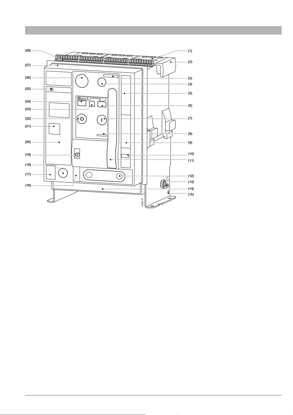
1 Construction
1.1 Circuit-breaker
(1) Arc chute a page 24 – 4
(2) Carrying handle
(3) Identification tags
(4) Motor cut-off switch (option) a page 14 – 3 or “Electrical ON”
(option) a page 14 – 3
(5) Circuit-breaker label a page2–1
(6) Stored-energy indicator a page 6 – 5
(7) “Mechanical ON” button
(8) Part no.
(9) Insertion pictograph
(10) Switching operations counter (option) a page 12 – 2
(11) Manual lever a page 6 – 4
(12) Crank handle a page 6 – 3
(13) Withdrawable unit transport shaft
(14) Options label a page 2 – 1
(15) Earthing terminal a page5–21
(16) Position indicator a page6–2
(17) Earth-fault tripping table (a page 9 – 17)
(18) Safety lock crank handle (option) a page 15 – 11
(19) Control rod (option) a page 15 – 3
(20) Overcurrent release a page9–1
(21) Rating plug a page 9 – 35
(22) Mechanical OFF button or Emergency-Stop pushbutton (option)
a page 14 – 3
(23) Ready-to-close indicator a page6–4
(24) Switch position indicator a page6–4
(25) Tripped indicator (Reset button) (a page6–6)
(26) Locking device, “Safe OFF” position (option) a page 15 – 15
(27) Front panel a page 24 – 6
(28) Plug connector for auxiliary contacts a page 5 – 16
08/07 AWB1230-1407GB 1 – 1
Page 10
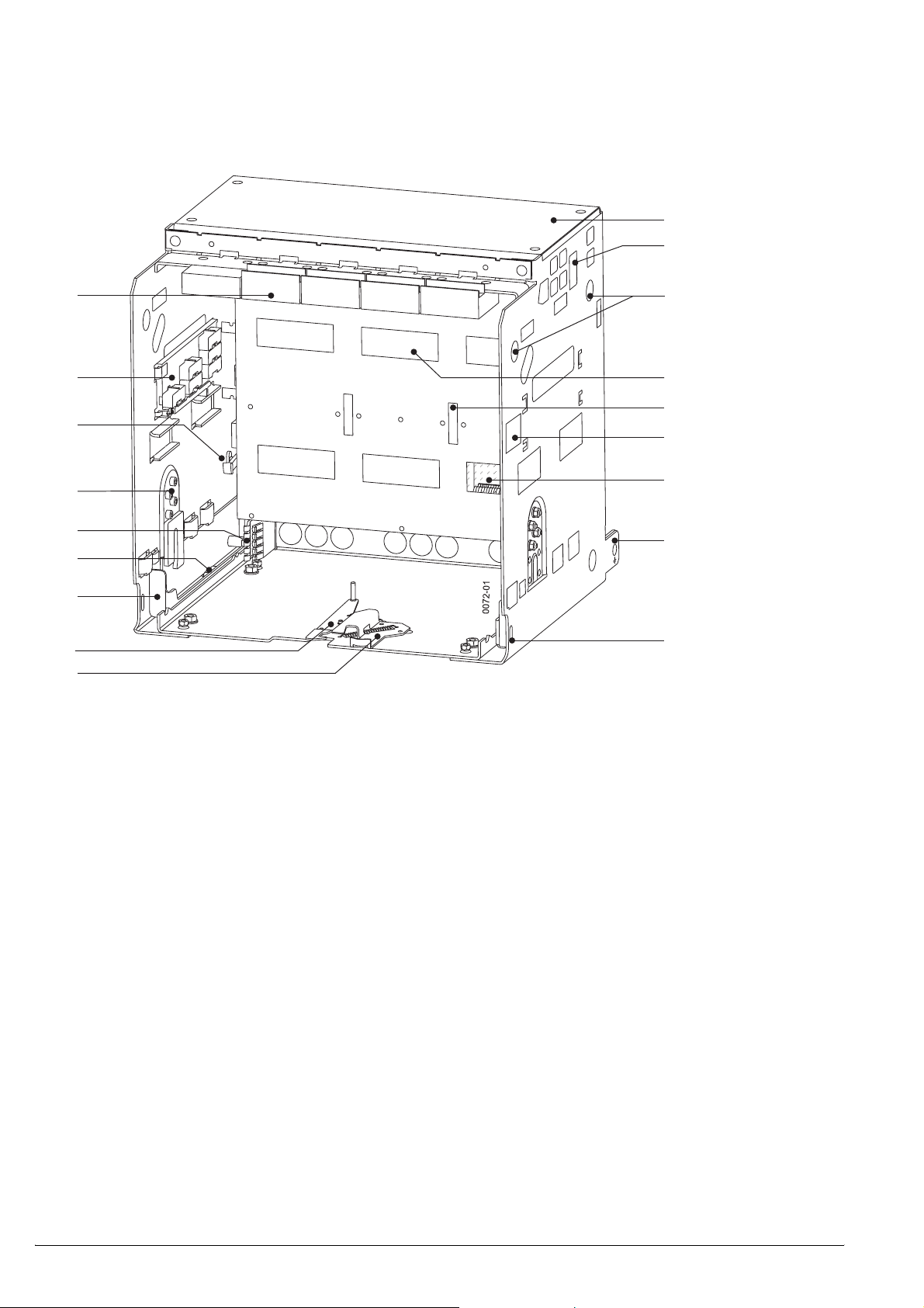
1.2 Withdrawable unit
(1)
(2)
(18)
(17)
(16)
(15)
(14)
(13)
(12)
(11)
(10)
(1) Arcing chamber cover (option) a page 21 – 1
(2) Outlets a page 5 – 19
(3) Hole for crane hook a page4–2
(4) Shutter (option) a page19–1
(5) Locking device shutter (a page 15 – 16)
(6) Withdrawable unit label a page2–3
(7) Laminated contacts (a page 5 – 11)
(8) Earthing terminal o 14 mm a page5–21
(9) Locking device guide rail a page 15 – 17
(10) Locking device to prevent racking with panel door open (option)
a page 17 – 2
(3)
(4)
(5)
(6)
(7)
(8)
(9)
(11) Door locking withdrawable unit (option) a page 17 – 2
(12) Guide rail a page6–1
(13) Factory setting rated current coding a page 19 – 5
(14) Switch ground sliding contact (on request)
(15) Equipment dependant coding (option) a page 19 – 6
(16) Shutter actuator a page 19 – 2
(17) Position signalling switch (option) a page 19 – 9
(18) Auxiliary sliding contacts module (quantity depends on
configuration) a page 5 – 17
1 – 2 08/07 AWB1230-1407GB
Page 11
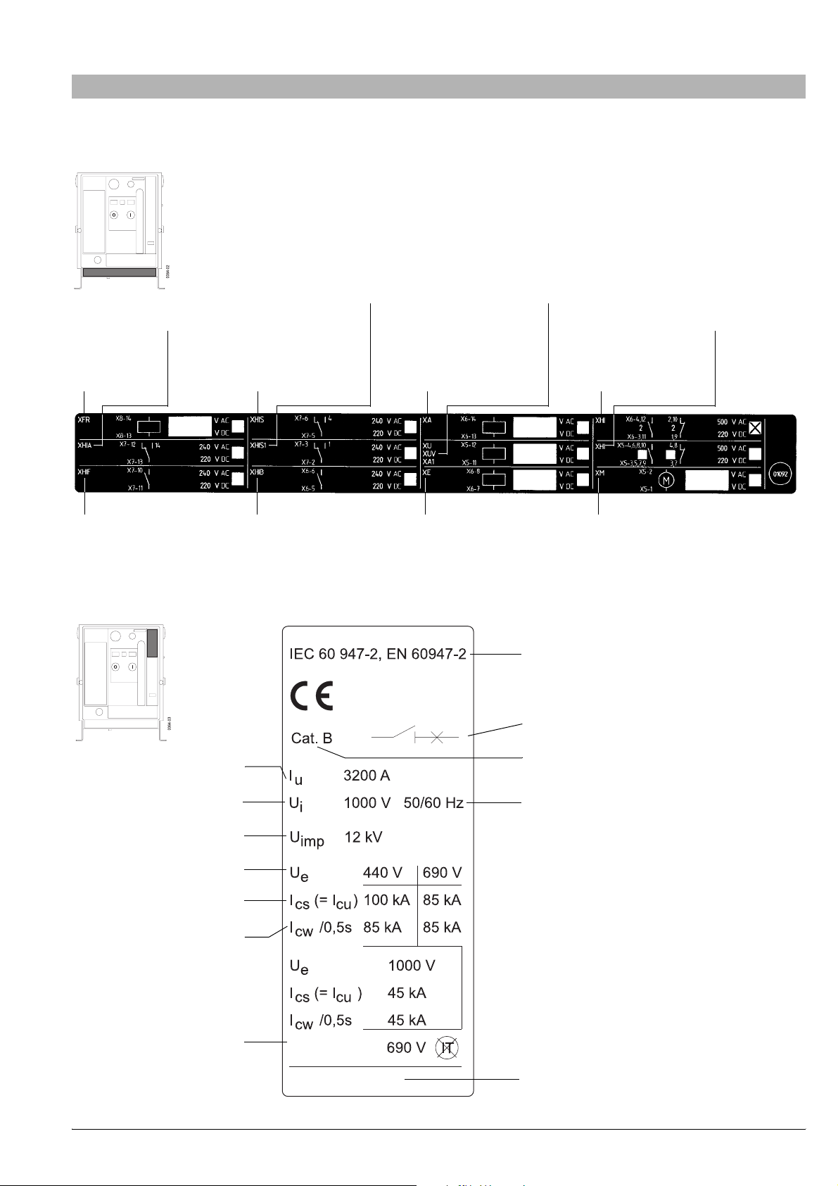
2 Labels
2.1 Circuit-breaker equipment label
(with terminal designations)
Tripped signalling switch
Signalling switch 1st
Remote reset
voltage release
Charge condition signalling
(on request)
auxiliary contact
2.2 Circuit-breaker label
Signalling switch 2nd
voltage release
1st shunt release
(Delayed) undervoltage
release or 2nd shunt
release
Additional auxiliary contacts
Standard auxiliary
contacts
BA_01092
Motor operatorClosing releaseReady-to-close
Standards
Max. rated current of the
Rated insulation voltage
Rated impulse withstand voltage
Rated operational voltage
Rated short-circuit breaking capacity
Rated short-time withstand current
Direction for use in IT systems
circuit-breaker
ID-Nr. 4912...
Disconnected function
Utilization category
Rated frequencies
Ident-No. circuit-breaker
08/07 AWB1230-1407GB 2 – 1
Page 12
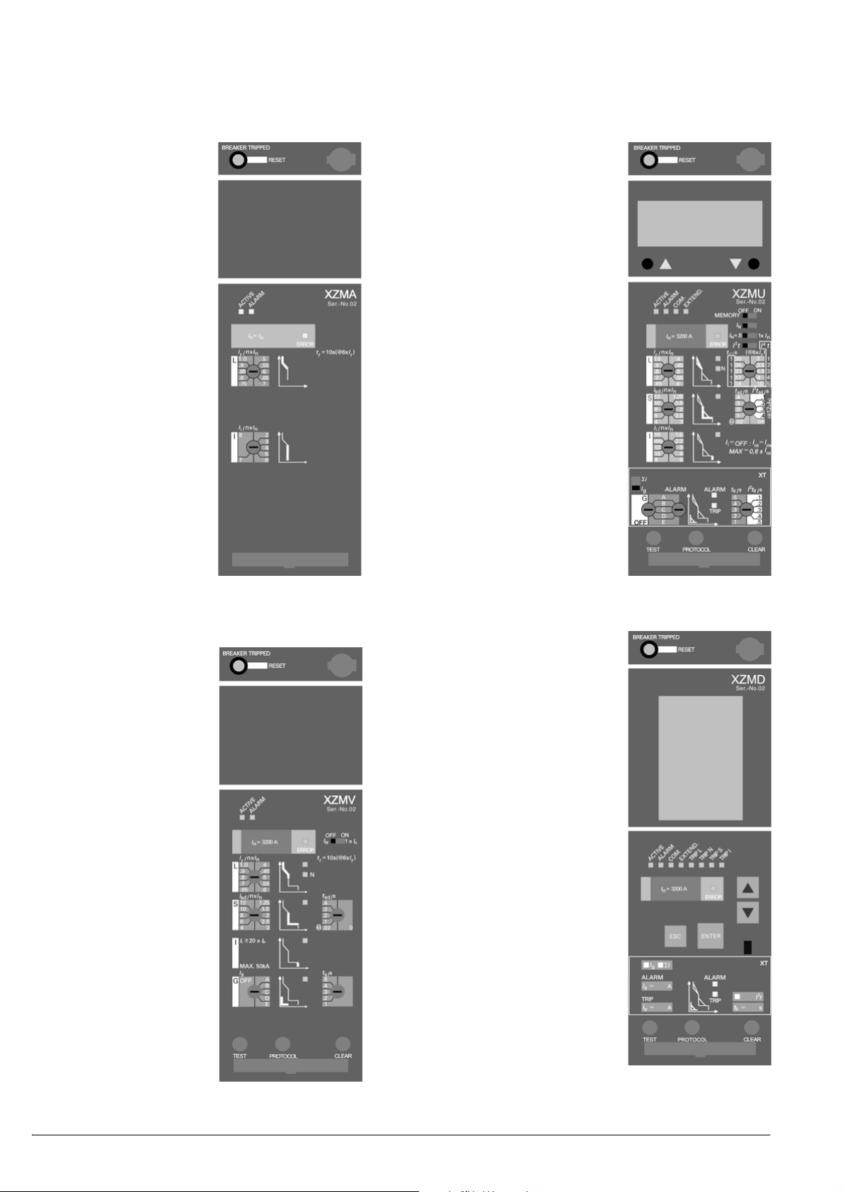
2.3 Identification of the control unit
IZM ...-A... Release for protection of systems
IZM ...-U... Release for universal protection
Options:
XT(A) Earth-fault
protection
N-conductor
protection
adjustable
XAM LCD-display
XCOM-DP Communication
interface
XMP(H) Measurement
module
IZM ...-V... Release for selectively-opening circuitbreakers
Options:
XT Earth-fault
protection
Neutral conductor
protection, can be
switched on/off
XZMA
XZMU
IZM...-D... Digital overcurrent release
Options:
XT(A) Earth-fault
protection
N-conductor
protection
adjustable
XCOM-DP Communication
interface
XMP(H) Measurement
module
XZMD+AMG
XZMV+T
2 – 2 08/07 AWB1230-1407GB
Page 13
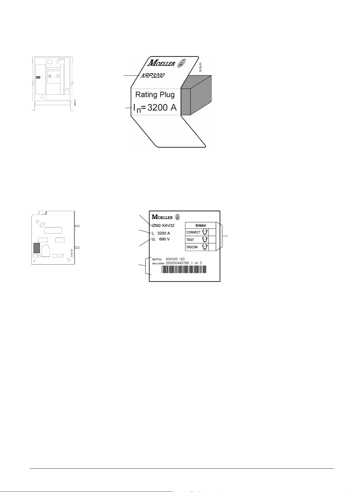
2.4 Rating plug label
Part no.
Rated current of the
circuit-breaker
2.5 Withdrawable unit label
Part no.
Withdrawable unit maximum
current rating
Rated insulation voltage
Internal handling numbers
Position signalling switch
0134
08/07 AWB1230-1407GB 2 – 3
Page 14

2 – 4 08/07 AWB1230-1407GB
Page 15

3 Standards and regulations
Danger
Dangerous voltage!
Can cause death, serious injury or damage to
material/property.
Only qualified personnel that are familiar with the
warning and safety notices and maintenance
instructions may work on the device.
Qualified personnel must have the skill and
experience in the operation of electrical equipment
and systems as well as their construction and
function. They should have taken part in safety
training concerning the dangers of electrical
equipment.
The effective and safe function of these devices is
dependant upon correct operation, installation,
handling and maintenance.
Qualified Personnel
For the purpose of this instruction manual and product
labels, a “qualified person” is one who is familiar with the
installation, construction and operation of the equipment
and the hazards involved. In addition, he has the following
qualifications:
a) Training or instruction in respectively, authorisation,
circuitry and device/systems in accordance with the
regulations for safe on and off switching, earthing and
identification.
b) Training or instruction in accordance with the regulations
for the safety features in care and application of
appropriate safety equipment.
c) Is trained in rendering first aid.
The circuit-breakers are suited for operation in enclosed spaces not
subject to operating conditions aggravated by dust, caustic vapours
or gases. Circuit-breakers to be installed in dusty or damp locations
must be appropriately enclosed.
The circuit-breaker is in conformity with the standards:
IEC 60947-2
EN 60947-2
DIN VDE 0660 Part 101
08/07 AWB1230-1407GB 3 – 1
Page 16

3 – 2 08/07 AWB1230-1407GB
Page 17

4 Transport
Unpack the circuit-breaker and inspect for damage. In case of later
installation of the circuit-breaker or withdrawable unit: They may be
stored and redispatched only in the original packing.
Transport packing
Red transport indicator
Arrow in the top half is partly or fully blue. Arrow in the top half is white
– Transport not according to instructions (switch was tilted or
overturned)
– Check circuit-breaker for transport damage
– Notify damages to forwarding agent
– Circuit-breaker was not tilted or overturned during transport
4.1 Overseas packing
Check humidity indicator Further storage
Pink Blue
Renew dessicant or seal tightly with dry plastic
Sealed packing ineffective. Check circuitbreaker for corrosion. Report damage to
transport company
Good
film Check packing regularly
4.2 Unpacking
Unpack the circuit-breaker and inspect for damages.
For later installation of circuit-breaker or withdrawable unit: Storage
and further shipment only in original packing.
CAUTION
Do not lay the circuit-breaker on it´s back!
08/07 AWB1230-1407GB 4 – 1
Page 18

4.3 Lifting by crane
m
Danger
Heavy device.
Incorrect lifting can cause death or serious
injury as well as damage to the device and
equipment.
Never lift a circuit-breaker, or a withdrawable
unit over a person. Follow the operating
instructions of the crane. Only use OSHA/
NIOSH tested crane harnesses. Use personnel
safety equipment to lift or move circuitbreakers and withdrawable unit.
Caution
Circuit-breaker Withdrawable unit
Do not put on the rear
side!
Frame size/No. of poles Weight
IZM(IN).1-... / 3
IZM(IN).1-... / 4
IZM(IN).2-... / 3
IZM(IN).2-... / 4
IZM(IN).3-... / 3
IZM(IN).3-... / 4
1) Hook cable above the label.
43 kg
50 kg
max. 64 kg
max. 77 kg
max. 90 kg
max. 108 kg
Circuit-breaker + Withdrawable
unit
o max. 12 m
m
1
f
m
1
f
25 kg
30 kg
max. 45 kg
max. 54 kg
max. 70 kg
max. 119 kg
o max 12 mm
1)
f
70 kg
84 kg
max. 113 kg
max. 136 kg
max. 166 kg
max. 227 kg
o max 12 mm
m
1
1)
4 – 2 08/07 AWB1230-1407GB
Page 19

5 Mounting
WARNING
Safe operation is dependent upon proper
handling and installation by qualified personnel
under observance of all warnings contained in
this instruction manual.
The general installation and safety regulations
for working on high current systems (e.g. DIN
VDE) and also standards concerning the
correct use of lifting equipment and tools and
the use of personal protection equipment
(safety glasses, etc.) should be especially
observed.
Non-observance can result in death, severe
personal injury or substantial property damage.
5.1 Installation
5.1.1 Mounting position
°
0
3
F
F
3
Danger
Heavy device.
Incorrect lifting can cause death or serious
injury as well as damage to the device and
equipment.
Never lift a circuit-breaker, or a withdrawable
unit over a person. Follow the operating
instructions of the crane. Only use OSHA/
NIOSH tested crane harnesses. Use personnel
safety equipment to lift or move circuitbreakers and withdrawable unit.
°
0
3
0
°
F
F
3
0
°
5.1.2 Mounting on horizontal surface
D h max. 1 mm
Fixing points
Non-removable nut
4 bolts M8-8.8
08/07 AWB1230-1407GB 5 – 1
4 bolts M8-8.8 + nuts + strain washers
If several withdrawable units are arranged one above the other in
cubicles without compartment bases we recommend the use of arc
chute covers (a page 21 – 1).
Page 20

5.1.3 Mounting on a vertical surface with mounting
brackets
For fixed-mounted circuit-breaker only.
Part no.
Mounting brackets (only for IZM(IN).1-... and
IZM(IN).2-...)
IZM1/2-XTW
4 bolts M10-8.8 + nuts + strain washers
Non-removable nut
4 bolts M8-8.8 + strain washers
Mounting dimensions
Representation of IZM(IN).2-... with front connection.
5 – 2 08/07 AWB1230-1407GB
Page 21

Dimension diagram, mounting brackets
o 13.5
o 20
43
9
113
342
172.5
20
o 9
23 402
16+0.5
452
30
16
20
o 11
455
400
20
34
40
17
17.5
152.5
212
337 5
08/07 AWB1230-1407GB 5 – 3
Page 22

5.1.4 Safety clearances
5.1.5 Safety clearance to earthed parts
Rated operational
voltage
[V AC] [mm] [mm] [mm]
IZM(IN).1-..., Fixed mounting
440 75
690 75
IZM(IN).1-..., Withdrawable, without arc chute cover
440 50
690 50
IZM(IN).1-..., Withdrawable, with arc chute cover
440 0 0
690 0 0
IZM(IN).2-..., Fixed mounting
440 75
690 75
1000 180 0 0
IZM(IN).2-..., Withdrawable, without arc chute cover
440 50
690 50
1000 100 0 0
IZM(IN).2-..., Withdrawable, with arc chute cover
440 0 0
690 0 0
IZM(IN).3-..., Fixed mounting
440 75
690 75
1000 180 0 0
IZM(IN).3-..., Withdrawable, without arc chute cover
440 50
690 50
1000 100 0 0
IZM(IN).3-..., Withdrawable, with arc chute cover
440 0 0
690 0 0
1) Value for plates, 0 mm for supports and grills.
2) 40 mm (IZM(IN).2-...: 70 mm) for plates that cover openings in drawer frame.
above control
circuit plug
1)
1)
1)
1)
1)
1)
1)
1)
1)
1)
1)
1)
Side (each) Rear
00
00
00
00
2)
2)
0
0
00
00
00
00
2)
2)
0
0
00
00
00
00
2)
2)
0
0
All safety clearances above the circuit-breaker are from the top
edge of the control circuit plug not the top edge of the arc chute!
a dimension drawings
5.1.5.1 Safety clearances to live parts
Rated operational
voltage
[V AC] [mm] [mm] [mm]
IZM(IN).1-..., Fixed mounting
440 150 20 20
690 300 50 125
IZM(IN).1-..., Withdrawable, without arc chute cover
440 150 20 14
690 300 50 14
IZM(IN).1-..., Withdrawable, with arc chute cover
440 14 100 14
690 14 100 14
IZM(IN).2-..., Fixed mounting
440 250 50 20
690 600 100 140
1000 430 100 125
IZM(IN).2-..., Withdrawable, without arc chute cover
440 250 50 14
690 600 100 30
1000 350 100 14
IZM(IN).2-..., Withdrawable, with arc chute cover
440 14 50 14
690 14 225 14
IZM(IN).3-..., Fixed mounting
440 75 20 20
690 500 100 125
1000 430 100 125
IZM(IN).3-..., Withdrawable, without arc chute cover
440 50 20 14
690 500 100 14
1000 350 100 14
IZM(IN).3-..., Withdrawable, with arc chute cover
440 14 50 14
690 14 200 14
above control
circuit plug
Side (each) Rear
5 – 4 08/07 AWB1230-1407GB
Page 23

5.1.6 Use in IT systems
5.1.7 Regulations
In IEC 60947-2 or EN 60947-2 “Low voltage switchgear Part 2:
circuit-breakers” for the use of circuit-breakers in an unearthed or
impedance earthed network (IT systems) an extra test to IEC
60947-2 Appendix H is required.
Subsequently the tests with 1.2 times the highest setting of the
short time delayed overcurrent trip (S trip) or the undelayed
overcurrent trip ( I trip) when no S trip is available, as single pole
short-circuit switch-off capacity I
maximum of 50 kA. The tests are to carried out with the phase
voltages of the highest rated operating voltage Ue for use in the
network.
With this the worst case fault that could occur in the IT system is
covered, with a double earth fault on the load and incoming sides
See following illustration:
are to be verified. This is for a
IT
e
690 V AC
L1
L2
L3
b
d
690 V
a
c
햲 Fault 1
햳 Fault 2
햴 Frame
햵 Impedance
햶 Transformer
Explanation:
– After fault 1 fault 2 then occurs.
– With that there is then a double earth fault on the load and
incoming sides.
– On the main contacts in phase L1 is then the full phase voltage of
e.g. 690 V.
– At the same time the contact must carry a high short-circuit
current.
08/07 AWB1230-1407GB 5 – 5
Page 24

5.1.7.1 Conditions for use in IT Systems
The IZM circuit-breaker fulfills the requirements for use in IT
systems with the standard IEC 60947-2 Appendix H demanded
maximum values with consideration of the following options and
safety clearances (blow-out space).
The details for the blow-out space above the control circuit plug is
based on the necessary blow-out space over the arc chute and
serves as additional information to users who want to bring their
Overview circuit-breaker IZM in IT systems
safety clearances to the appropriate highest point of the device
(control circuit plug). The short-circuit breaking capacity shown in
the table I
corresponds to the maximum demanded value in the
IT
standard IEC 60947-2 Appendix H , to fulfill an acceptibility in the IT
systems with the respective rated operating voltage U
The circuit-breakers of type IZM1 cannot be used in 690 V IT
systems, here the option IZM...-X1000 V is generally suitable.
to IEC 60947-2 or EN 60947-2 Appendix H
Type (3/4-pole)
IZM1 IZM2 IZM3
Rated operating voltage Ue F 440 V
– Single pole short-circuit breaking capacity I
IT
kA 23 50 50
– neccessary options – – –
– minimum required blow-out space above arc chute. mm 100 100 50
– corresponding minimum blow-out space above control circuit plug.
mm 70/40 70/40 20/0
(fixed/withdrawable)
– labelling to IEC 60947-2 Appendix H 690 V 690 V 500 V
ITIT ITIT ITIT
Rated operating voltage Ue F 500 V
– Single pole short-circuit breaking capacity IIT kA 23 50 50
– neccessary options – – –X1000 V
– minimum required blow-out space above arc chute. mm 150 150 50
– corresponding minimum blow-out space above control circuit plug.
mm 120/90 120/90 65/0
(fixed/withdrawable)
– labelling to IEC 60947-2 Appendix H 690 V 690 V 1000 V
ITIT ITIT ITIT
Rated operating voltage Ue F 690 V
– Single pole short-circuit breaking capacity IIT kA – 50 50
– neccessary options – –X1000 V
2)
–X1000 V
– minimum required blow-out space above arc chute. mm – 50 50
– corresponding minimum blow-out space above control circuit plug.
mm – 65/0 65/0
(fixed/withdrawable)
– labelling to IEC 60947-2 Appendix H 690 V 1000 V 1000 V
ITIT ITIT ITIT
.
e
1)
1)
1) –X1000 V ist option IZM...-X1000 V for rated operating voltage Ue = 1000 V AC
2) Exception: IZM...2-(4-)A(V)800...1600, this circuit-breaker fulfills the
requirement for 690V IT networks corresonding to IEC 60947-2, Appendix H
(contrary to the details on the rating label: )
ITIT
5.1.8 Labelling of the IZM circuit-breaker
The standard IEC 60947-2 Appendix H demands the labelling of
devices that are in their existing features not suitable for IT
networks for all values of the rated operating voltage and the
corresponding types or sizes. The following symbol must be directly
behind the rated operating voltage e.g. 690 V .
ITIT
The labelling for single sizes and voltages can be seen in the above
table.
5 – 6 08/07 AWB1230-1407GB
Page 25

5.2 Connecting bars
a Frame sizes, dimension drawings (page 7 – 1)
5.2.1 Horizontal connection
The horizontal connection is up to 5000 A including the standard
connection for fixed-mounted circuit-breakers and withdrawable
unit.
o 13.5 mm
For withdrawable unit only:
a Retrofit installation of horizontal connections (page 5 – 12)
5.2.2 Flange connection
(only for withdrawable)
M 12
The mounting of the flange connection is similar to the mounting of
the vertcal and horizontal connections (a page 5 – 12)
70
± 4 Nm
X
08/07 AWB1230-1407GB 5 – 7
Screw-in depth:
x = 18...24 mm
Page 26

5.2.3 Front connection
Note
When front connections are used, a partition between busbar and
arcing space must be fitted on the system side.
Fixed-mounted circuit-breaker
Two variations are offered:
(1) Standard version: single-hole fitting
(2) Version double-hole fitting
(3) Holes o 13.5
(1)
(2)
(3)
Fastening connecting bars:
(1) (2)
85 Nm
Size 5
8 Nm
(1) For
IZM(IN).1-...
IZM(IN).2-...
(2) For
IZM(IN).1-...
IZM(IN).2-...
IZM(IN).3-...
(3) Long connecting bar
(4) Short hexagon socket screw ISO 4762 M6 with strain washer
(5) Short spacer
(6) Coach screw DIN 603 M12 with strain washer and nut
(7) Long distance sleeve
(8) Long hexagon socket screw ISO 4762 M6 with strain washer
(9) Short connecting bar
F 1000 A and
F 2000 A
1600 A
2500 A, 3200 A
4000 A
(3)
(4)
(5)
(6)
(7)
(8)
(9)
85 Nm
Size 5
8 Nm
5 – 8 08/07 AWB1230-1407GB
Page 27

Withdrawable unit
Two variations are offered:
(1) Standard version: single-hole fitting
(2) Version double-hole fitting
(3) Slots for phase separation walls; mounting position as shown!
(4) Support
(5) Holes o 13.5
Fastening connecting bars:
(1)
(2)
(3)
(4)
(5)
(1) (2)
(3)
85 Nm
(4)
(5)
Size 5
10 Nm 10 Nm
(1) For
IZM(IN).1-...
IZM(IN).2-...
(2) For
IZM(IN).1-...
IZM(IN).2-...
IZM(IN).3-...
(3) Hexagon socket screw ISO 4762 M6 with strain washer
(4) Support; mounting position as shown!
(5) Coach screw DIN 603 M12 with strain washer and nut
F 1000 A and
F 2000 A
1600 A
2500 A, 3200 A
4000 A
85 Nm
Size 5
Conversion from vertical or flange connection to front
connection requires installation of horizontal connection first!
a (page5–11)
08/07 AWB1230-1407GB 5 – 9
Page 28

5.2.4 Vertical connection
Fixed-mounted circuit-breaker
Size
IZM(IN).1-... 1000 A
1) 2 connection bars per main connection,
above and below fixing by offset slot,
a Picture for IZM(IN).2-...
Rated current
1)
1600 A
.
Size
IZM(IN).2-...
Rated current
2500 A1)
3200 A
1) 1 connect bar per main connection, middle fixing,
a Picture for IZM(IN).1-...
1 × M12-8.8 + nut
+ spring washer (above + below)
2 × o 13.5 mm
3 × M12-8.8 + nut
+ spring washer (above + below)
3 × o 13.5 mm
85 Nm
85 Nm
Size
IZM(IN).3-...
Rated current
5000 A
4 × M12-8.8 + nut
+ spring washer (above + below)
4 × o 13.5 mm
85 Nm
5 – 10 08/07 AWB1230-1407GB
Page 29

Withdrawable unit
Size
IZM(IN).1-... 1000 A, 1600 A
Size
IZM(IN).3-... 6300 A
Rated current
1 × M 6
2 x o 13.5
Rated current
Size
IZM(IN).2-... 2000 A, 2500 A
Rated current
A
3200
2 × M 6
3 x o 13.5
Size
IZM(IN).3-... 5000 A
Vertical connections left and right
asymmetric
Rated current
2 × M 6
4 x o 13.5
Removal of lamelle contacts
Rear side of withdrawable unit
2
3
1
08/07 AWB1230-1407GB 5 – 11
Page 30

Removing horizontal connection
Rear drawer area
2
Size 5
Combination
screw M6x20
Installing vertical connection
Rear drawer area Combination screw M6x20
1
3
2
4
1
8 Nm
3
Mounting steps for installation of horizontal or flange connection are similar.
Note
The lamelle blocks for circuit-breaker IZM(IN).3-..., 4000 A, are not
fully equiped with lamelle.
4
ATTENTI O N
Only use similarly equiped lamelle blocks for assembly.
5 – 12 08/07 AWB1230-1407GB
Page 31

Order numbers
Connecting bars fixed-mounted circuit-breaker Frame size Rated current I
F 1000 A (+)IZM1-XAT1F10-0
IZM(IN).1-...
1250 A...1600 A (+)IZM1-XAT1F16-0
F 2000 A (+)IZM2-XAT1F20-0
Front connection (single-hole fitting) top
IZM(IN).2-...
2500 A (+)IZM2-XAT1F25-0
3200 A (+)IZM2-XAT1F32-0
IZM(IN).3-... F 4000 A (+)IZM3-XAT1F40-0
F 1000 A (+)IZM1-XATF10-0
IZM(IN).1-...
1250 A...1600 A (+)IZM1-XATF16-0
F 2000 A (+)IZM2-XATF20-0
Front connection (double-hole fitting) top
IZM(IN).2-...
2500 A (+)IZM2-XATF25-0
3200 A (+)IZM2-XATF32-0
IZM(IN).3-... F 4000 A (+)IZM3-XATF40-0
F 1000 A (+)IZM1-XAT1F10-U
IZM(IN).1-...
1250 A...1600 A (+)IZM1-XAT1F16-U
F 2000 A (+)IZM2-XAT1F20-U
Front connection (single-hole fitting) bottom
IZM(IN).2-...
2500 A (+)IZM2-XAT1F25-U
u
Part no.
Front connection (double-hole fitting) bottom
Vertical connection
1)IZM1-XATV16 = 2x IZM1-XATV10
2)IZM2-XATV32 = 2x IZM2-XATV25
3200 A (+)IZM2-XAT1F32-U
IZM(IN).3-... F 4000 A (+)IZM3-XAT1F40-U
F 1000 A (+)IZM1-XATF10-U
IZM(IN).1-...
1250 A...1600 A (+)IZM1-XATF16-U
F 2000 A (+)IZM2-XATF20-U
IZM(IN).2-...
2500 A (+)IZM2-XATF25-U
3200 A (+)IZM2-XATF32-U
IZM(IN).3-... F 4000 A (+)IZM3-XATF40-U
F 1000 A (+)IZM1-XATV10
IZM(IN).1-...
1600 A (+)IZM1-XATV16
1)
F 2500 A (+)IZM2-XATV25
IZM(IN).2-...
3200 A (+)IZM2-XATV32
2)
IZM(IN).3-... F 5000 A (+)IZM3-XATV50
08/07 AWB1230-1407GB 5 – 13
Page 32

Connecting bars withdrawable unit Frame size Rated current I
F 1000 A (+)IZM1-XAT1F10-AV
IZM(IN).1-...
1250 A...1600 A (+)IZM1-XAT1F16-AV
Front connection (single-hole fitting)
When these connections are ordered individually, additional
supports must also be ordered.
IZM(IN).2-...
F 2000 A (+)IZM2-XAT1F20-AV
2500 A (+)IZM2-XAT1F25-AV
3200 A (+)IZM2-XAT1F32-AV
IZM(IN).3-... F 4000 A (+)IZM3-XAT1F40-AV
u
Part no.
Front connection (double-hole fitting)
When these connections are ordered individually, additional
supports must also be ordered.
3-pole for 3 front
Supports for front connections with
connections
withdrawable unit
2 supports per switch required
4-pole for 4 front
connections
Vertical connection
IZM(IN).1-...
F 1000 A (+)IZM1-XATF10-AV
1250 A...1600 A (+)IZM1-XATF16-AV
F 2000 A (+)IZM2-XATF20-AV
IZM(IN).2-...
2500 A (+)IZM2-XATF25-AV
3200 A (+)IZM2-XATF32-AV
IZM(IN).3-... F 4000 A (+)IZM3-XATF40-AV
IZM(IN).1-... F 1600 A IZM1-XATFS
IZM(IN).2-... F 3200 A IZM2-XATFS
IZM(IN).3-... F 4000 A IZM3-XATFS
IZM(IN).1-4-... F 1600 A IZM1-XATFS4
IZM(IN).2-4-... F 3200 A IZM2-XATFS4
IZM(IN).3-4-... F 4000 A IZM3-XATFS4
F 1000 A (+)IZM1-XATV10-AV
IZM(IN).1-...
1250 A...1600 A (+)IZM1-XATV16-AV
F 2000 A (+)IZM2-XATV20-AV
IZM(IN).2-...
2500 A (+)IZM2-XATV25-AV
3200 A (+)IZM2-XATV32-AV
Flange connection
IZM(IN).3-... F 5000 A (+)IZM3-XATV50-AV
F 1000 A (+)IZM1-XATA10-AV
IZM(IN).1-...
1250 A...1600 A (+)IZM1-XATA16-AV
F 2000 A (+)IZM2-XATA20-AV
IZM(IN).2-...
F 2500 A (+)IZM2-XATA25-AV
F 3200 A (+)IZM2-XATA32-AV
IZM(IN).3-... F 4000 A (+)IZM3-XATA40-AV
5 – 14 08/07 AWB1230-1407GB
Page 33

5.3 Connection of main conductors
Main conductor - minimum cross section:
Frame size Rated current
I
u
[A] [mm2]
Cross section Cu bars
bare/bare black/bare
1)
630 1 × 40 × 10 1 × 40 × 10
800 1 × 50 × 10 1 × 60 × 10
IZM(IN).1-...
1000 1 × 60 × 10 1 × 60 × 10
1250 2 × 40 × 10 2 × 40 × 10
1600 2 × 50 × 10 2 × 50 × 10
800 1 × 50 × 10 1 × 50 × 10
1000 1 × 60 × 10 1 × 60 × 10
1250 2 × 40 × 10 2 × 40 × 10
IZM(IN).2-...
1600 2 × 50 × 10 2 × 50 × 10
2000 3 × 50 × 10 3 × 50 × 10
2500 2 × 100 × 10 2 × 100 × 10
3200 3 × 100 × 10 3 × 100 × 10
4000 4 × 100 × 10 4 × 100 × 10
IZM(IN).3-...
5000 5 × 100 × 10 5 × 120 × 10
6300 6 × 120 × 10 6 × 120 × 10
1) Other Cu bar sizes possible, but the total Cu cross section must not be less.
2) Aluminium bars - please enquire.
2)
[mm2]
1)
Cleaning the copper bars
Steel-wire brush
Bolt tight line-side bars
Bracing the main conductors
Metal cuttings
Remove
ATTENTION
On 4-pole circuit-breakers, the neutral conductor must
always be connected all on the left (front view).
Otherwise this can cause malfunctions of the electronic
overcurrent release.
Connection of cables directly on the circuit-breaker
connections is not permissible.
Cleaning the main conductor connection
Circuit-breaker
08/07 AWB1230-1407GB 5 – 15
Page 34

5.4 Auxiliary conductor connection
Retrofitting
Terminal assignment:
a Circuit diagrams (page 8 – 1)
Cross section connection type
1 x 2 x
Strip conductors
Screw terminals
0.5 – 2.5 mm
AWG 20...14
+
7 mm
Spring-loaded
terminals
Wire end ferrule
0.5 – 2.5 mm
AWG 20...14
+
Wire end ferrule
7 mm
1) 1 x up to 2.5 mm2 tubular without plastic sheath to DIN 46228 T1
1 x up to 1.5 mm
2 x up to 1.5 mm
2) 2 x up to 2.5 mm
2 x up to 1.5 mm
2
tubular with plastic sheath to DIN 46228 T2
2
tubular with plastic sheath, twin ferrules
2
tubular without plastic sheath to DIN 46228 T1
2
tubular with plastic sheath to DIN 46228 T2
2
1)
2
2)
0.5 – 1.5 mm
AWG 20...15
+
Wire end ferrule
0.5 – 2.5 mm
AWG 20...14
+
Wire end ferrule
2
2
1
3
(2)
(1)
2
1)
2)
(1) Blanking cover
(2) Plug connector
Only for circuit-breakers, 1000 V version
0173-06
4
5.4.1 Plug connector
Arrangement
COM-DP
(1) Arc chute
(2) Plug connector
5
(3)
(1)
(2)
X6X7X8
X5
0173-09
6
PH 1
0.7 N
m
(3) Knife-contact rail adapter for higher arc chute
5 – 16 08/07 AWB1230-1407GB
Page 35

Spring-loaded terminals
3.0 × 0.6
5.4.3 Control circuit plug
Screw terminals
Connecting wires
5.4.2 Sliding contact module
Retrofitting
(2)
3.0 × 0.6
Spring-loaded terminals
(1)
3.0 × 0.6
2 terminals in parallel per contact
Attach guide tongues
(fixed-mounted circuit-breaker only)
2
1
(1) Connection area with sliding contact modules
(2) Sliding contact module
A single piece sliding contact module is also available with standard
screw terminals.
3.0 × 0.6
Single-piece sliding contact modules don´t require a control circuit
plug. The cable is directly connected to the sliding contact module.
Back side of
auxiliary connector
0769
08/07 AWB1230-1407GB 5 – 17
Page 36

Coding (only fixed-mounted circuit-breakers)
3
2
(1)
1
click
(1) Groove
(2) Guide
(3) Modul labelling (here X5; must show at front)
(4) Module X5
Fitting auxiliary connectors
L
(1)
X6.
X5
X6.
X5
0100-01_nu
X6.
X5
(2)
(3)
(4)
1
2
(2)
(1) Control circuit plug
(2) Fixed mounting: Knife contact rail
Withdrawable: Sliding contact module
5 – 18 08/07 AWB1230-1407GB
Page 37

5.4.4 Wiring on withdrawable unit
a
Danger
Impermissible area for wires:
Wires could be damaged.
Arcing space*)
Carrying h
Outlets
Interlocks
*)When arc chute cover is used control circuit wires must not be laid on this cover..
5.4.5 Assembly with control circuit connections
Terminal X6 always available. Depending upon the equiping of the
circuit-breaker with additional accessories other terminals are
necessary.
If necessary, with additional accessories the corresponding knife
contact rail, control circuit plug and for connection area also sliding
contact module must be retrofitted.
Ter mina l Optional accessories
X5 – Motor drive with storage with mechanical and electrical
X7 – Activated- signalling switch S24
X8 – Overcurrent release XZMU, XZMD (internal System
release.
– 2. Auxillary release (shunt release F2, undervoltage
release F3, delayable undervoltage release F4)
– Control circuit switch S3 + S4 or S7 + S8 or S3 + S8
– Motor cut-off switch S12 (only possible when motor
drive selected)
– Stored condition indication S21
– Electrical ON pushbutton S10
st
– Signalling switch on 1
– Signalling switch on 2
bus)
– Connection for external current transformer for
overload protection in N conductor and earth fault
protection
– Current transformer mounted in N conductor
– Current transformer mounted in star point of
transformer
– Remote reset magnet F7
– External voltage transformer
release S22
nd
release S23
5.4.6 Order numbers
Auxiliary conductors Order numbers
A Control circuit plug with screw terminals IZM-XKL-HS
B Spring-loaded terminals auxiliary
conductor
C Sliding contact module screw fixing /
standard (only for withdrawable)
D Sliding contact module optional (only for
withdrawable)
E Knife contact rail spring fixing IZM-XKL-ML
F Blanking cover (instead of a plug
connector)
G Coding set for fixed mounting for 4 control
circuit plugs (not necessary for
withdrawable)
H For 1000 V withdrawable the following
device is addditionally necessary:
Additional knife contact rail for adpation on
higher arc chute
IZM-XKL-HZ
IZM-XKL-SS
IZM-XKL-SK
IZM-XKL-B
IZM-XKL-C
IZM-XKL-AML1000V
08/07 AWB1230-1407GB 5 – 19
Page 38

Connection possibilities of the control circuit connections
C
ith
S
Fixed mounted
Connection with screw terminals
(standard)
Screwless connection (springloaded terminals) (option)
Withdrawable units
IZM-XKL-HS
NSE0_00975a
Plug connector on basic unit
IZM-XKL-ML
onnection w
(option)
IZM-XKL-HZ
NSE00978
screw terminals
NSE0_00976a
crewless connection (spring-
loaded terminals) (option)
IZM-XKL-C
Coding
(only for fixed
mounting)
NSE00974
NSE00973
Sliding contact module with screw fixing for
withdrawable (standard)
0769_1
IZM-XKL-SS
IZM-XKL-HS
Plug connector on basic unit
NSE00978
IZM-XKL-ML
NSE0_00975a
IZM-XKL-HZ
Sliding contact module for withdrawable
(option)
IZM-XKL-SK
N S E 0 _ 0 0 9 7 7 a
NSE0_00976a
5 – 20 08/07 AWB1230-1407GB
Page 39

5.5 Connection of protective conductor
5.5.1 Fixed-mounted circuit-breaker
5.5.2 Withdrawable unit
o 14 mm
o 14 mm
5.6 Changeover of fixed mounting circuit-breaker into withdrawable circuit-breaker
Note
For the changeover of your circuit-breaker our Field Service can be
used.
To contact Field Service: a chapter 26.
– Switching off and discharging the storage spring
(a page 24 – 2)
– Remove fixed-mounted circuit-breaker(a page5–1)
– Remove terminals other than horizontal terminals
(a page5–7)
– Remove front panel (a page 24 – 6)
– Remove overcurrent release (a page 9 – 39)
– Install rated current coding on the new circuit-breaker feet and on
the withdrawable unit (a page 19 – 5)
08/07 AWB1230-1407GB 5 – 21
Page 40

5.6.1 Conversion
Replacing circuit-breaker feet
2
Size 4
1
Size 4
3
10 Nm
4
1 Loosen and remove 3 M6x20 countersunk screws
2 Remove foot of fixed-mounted circuit-breaker
3 Replace by foot for withdrawable circuit-breaker
4 Attach the circuit-breaker foot with 3 countersunk M6x20 screws
Size 5
*Nm
2
1 Install racking mechanism
2 When threaded holes exist bolt the racking mechanism tight with
M6x12 cheese-head screw, strain washer and 6x18x3 washer.
When no screw thread exists grease a self-tapping screw and
screw in.
*) Tightening toque :machine screw 6 Nm
self-tapping screw 5 Nm
Installing racking shaft
Installing racking mechanism
1
1
3
2
1 Insert racking shaft
2 Fit crank
3 Secure crank handle with circlip DIN 471-17x1
5 – 22 08/07 AWB1230-1407GB
Page 41

Knock out front panel
1
1 Knock-out section from operating panel; use suitable support
2 Deburr the edges
2
Conversion kit part numbers
Conversion kit for fixed-mounted into withdrawable circuit-breaker.
Frame size Part no.
IZM(IN).1-... IZM1-XUS-AV
IZM(IN).1-4-... IZM1-XUS4-AV
IZM(IN).2-... IZM2-XUS-AV
IZM(IN).2-4-... IZM2-XUS4-AV
IZM(IN).3-... IZM3-XUS-AV
IZM(IN).3-4-... IZM3-XUS4-AV
Note
Conversion kits can only be ordered using the part no. shown above
and also giving the Indent no. of the circuit-breaker.
Fix adhesive label at the front panel
Then:
– Fit control gate(a page 15 – 3)
– Install overcurrent release (a page 9 – 39)
– Install front panel (a page 24 – 13)
– Assemble the required terminals on the withdrawable unit (must be
ordered separately) (a page5–7)
– Install withdrawable unit (a page5–1)
– Insert the circuit-breaker in the withdrawable unit and rack into
connected position (a page 6 – 1)
08/07 AWB1230-1407GB 5 – 23
Page 42

5 – 24 08/07 AWB1230-1407GB
 Loading...