

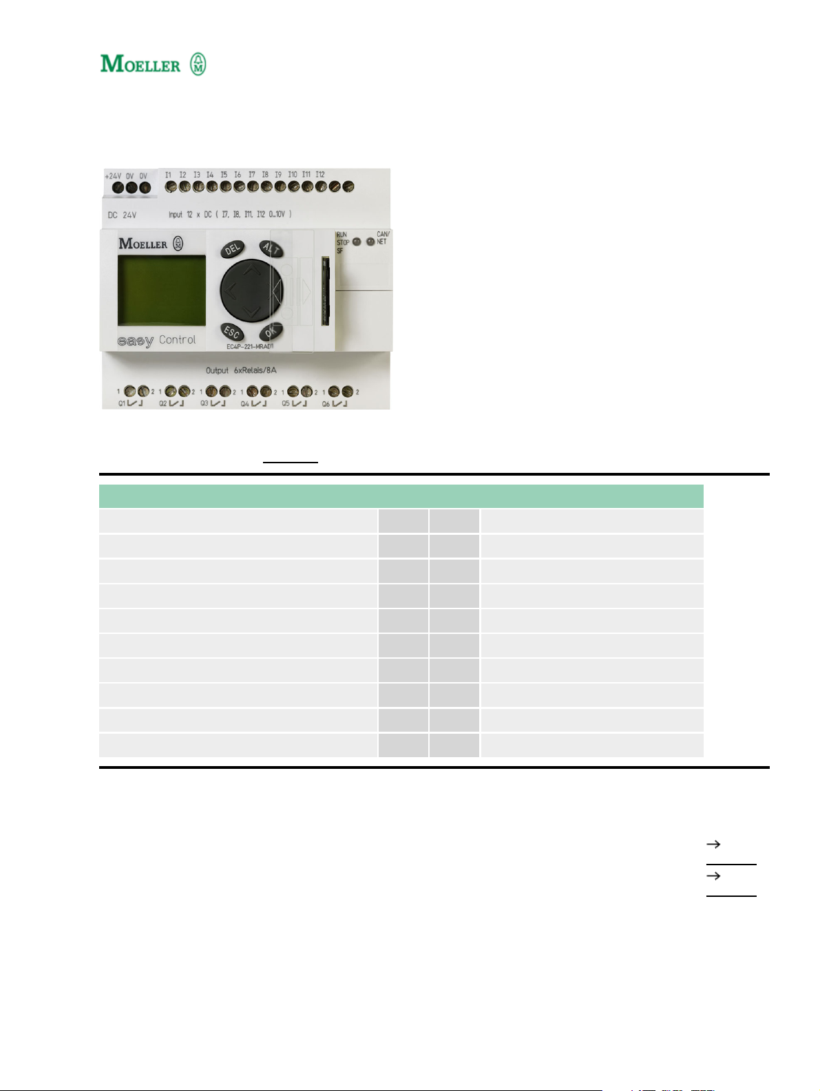
Type: EC4P−221−MTAD1
Article No.: 106395
Sales text 24 VDC,Can,12E,8Trans.,Displ.,Analog QA
Expandable: Inputs/outputs and bus systems Individual laser inscription possible with
EC4−COMBINATION−* 107600
Ordering information
Description easy−NET/CANopen on board
Inputs
Digital 12
of which can be used as analog 4
Outputs
Transistor 8
Analog 1
Additional features
Display & keypad
Supply voltage 24 V DC
Notes concerning the product group
Accessories Page
1 Power supply unit/communication module
2 Display/keypad
274095
265251
1
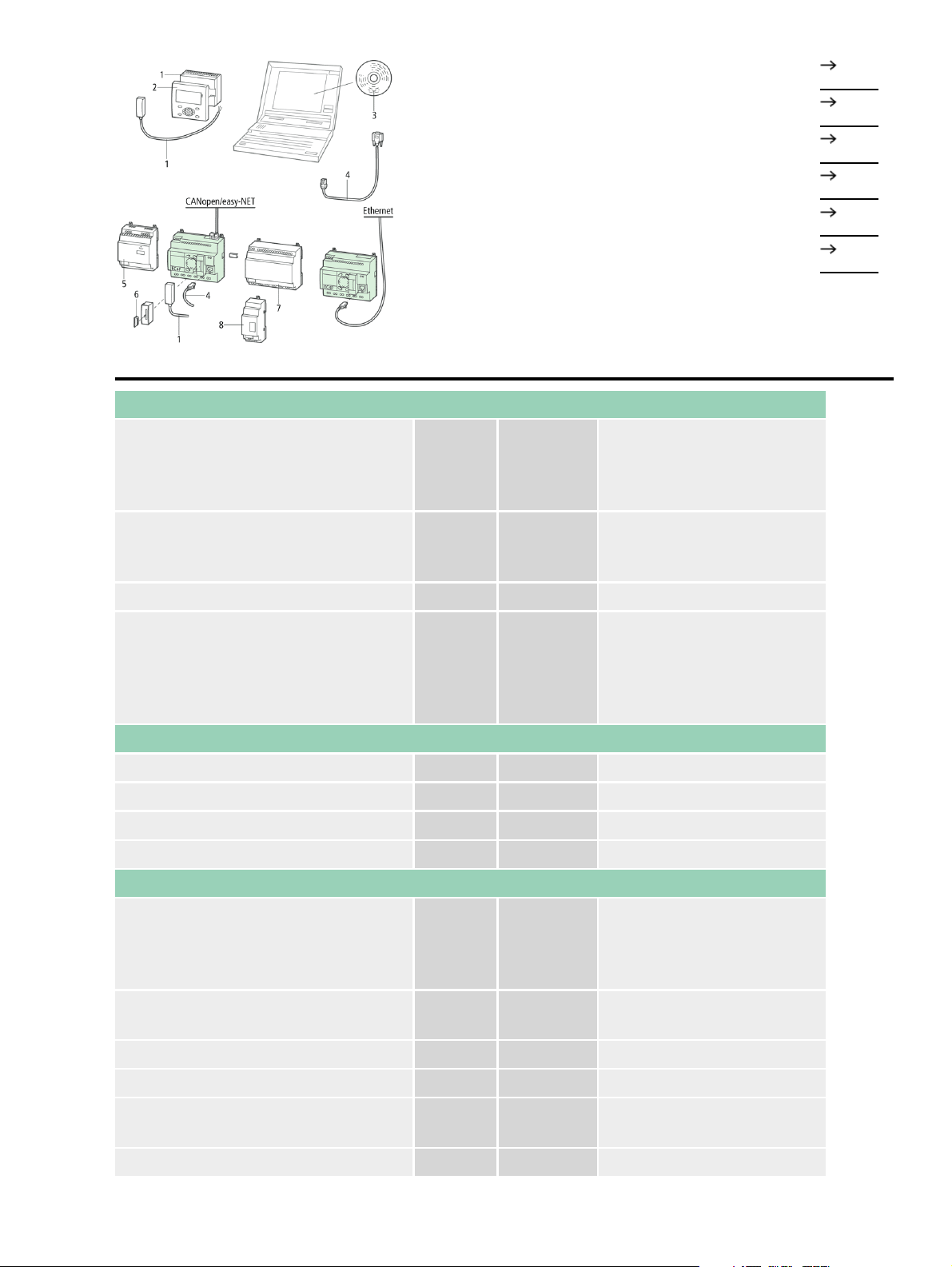
3 Programming software
106407
4 PC programming cable
5 Switched−mode power supply unit
6 Memory card
7 I/O expansion
8 Output expansion, bus module, coupling module
General
Standards
Dimensions (W × H × D) mm
106726
212319
106409
212314
212315
EN 55011, EN 55022,
IEC/EN 61000−4, IEC
60068−2−6, IEC
60068−2−27
107.5 × 90 × 72 without/79
with adapter for MCC (6
SU)
Weight kg 0,32
Top−hat rail IEC/EN 60715,
35 mm or screw fixing using
Mounting
3 fixing brackets
ZB4−101−GF1
(accessories)
Terminal capacities
Solid mm
Flexible with ferrule mm
2
0.2/4 (AWG 22 – 12)
2
0.2/2.5 (AWG 22 – 12)
Standard screwdriver mm 3.5 × 0.8
Max. tightening torque Nm 0,6
Climatic environmental conditions
–25 ... 55, low temperatures
Operating ambient temperature °C
to IEC 60068−2−1, high
temperatures to IEC
60068−2−2
Condensation
Take appropriate measures
to prevent condensation
LCD display (clearly legible) °C 0...55
Storage °C ... 40...+70
Relative humidity, non−condensing
(IEC/EN 60068−2−30)
% 5...95
Air pressure (operation) hPa 795...1080
2

Corrosion resistance
IEC/EN 60068−2−42
IEC/EN 60068−2−43
4 days
SO
2
4 days
H2S
cm3/m
cm3/m
3
10
3
1
Ambient conditions, mechanical
Degree of protection IEC/EN 60529 IP 20
Vibrations (IEC/EN 60068−2−6)
Constant amplitude 0.15 mm Hz 5...9
Constant acceleration 2 g Hz 8...150
Mechanical shock resistance
(IEC/EN 60068−2−27)
Impacts 18
semi−sinusoidal 15 g/11 ms
Drop to IEC/EN 60068−2−31
Free fall, packaged (IEC/EN
60068−2−32)
Drop
height
mm 50
m 1
Mounting position Horizontal/vertical
Electromagnetic compatibility (EMC)
Electrostatic discharge (IEC/EN
61000−4−2, Level 3, ESD)
Air discharge kV 8
Contact discharge kV 6
Electromagnetic fields (IEC/EN
61000−4−3, RFI)
V/m 10
Radio interference suppression (EN
55011)
Burst pulses (IEC/EN 61000−4−4,
level 3)
Supply cables kV 2
Signal lines kV 2
High−energy pulses (surge) (IEC/EN
61000−4−5)
High−energy pulses (surge) (IEC/EN
61000−4−5, level 2)
Immunity to line−conducted
interference to (IEC/EN 61000−4−6)
kV
kV
V 10
EN 55011 Class B, EN
55022 Class B
2 (supply cables,
symmetrical, EASY...AC)
0.5 symmetrical, 1
asymmetrical
Insulation resistance
Clearance in air and creepage
distances
EN 50178, UL 508, CSA
C22.2, no. 142
Insulation resistance EN 50178
Back−up/Accuracy of the real−time clock
3

Accuracy of the real−time clock s/day Normally ± 5 (± 0.5 hyear)
Retentive memory
Write cycles of the retentive memory
10000000000 (10¹)
(Read−write cycles)
Power supply
Rated operational voltage U
e
V 24 DC (−15/+20%)
Admissible range V DC 20,4...28,8
Residual ripple % 5
Input current
Input current 115/230 V AC mA Normally 140
Voltage dips (IEC/EN 61131−2) ms 10
Heat dissipation W typ.A3.4C
CPU
Microprocessor Infineon XC161
Memory
Program code/data kByte
256/14 segments of 16 KB
each
Marker/Input/Output/Retain data KByte 16/4/4/8
Cycle time for 1 k of instructions (Bit,
Byte)
ms <0,3
Interfaces
CANopen/easy−NET
500 kBit/s, 25 m 250 kBit/s,
Data transfer rate/distance
60m 125 kBit/s, 125 m 50
kBit/s, 300 m 20 kBit/s, 700
m 10 kBit/s, 1000 m
Potential isolation
From power supply Yes
From the inputs Yes
From the outputs Yes
Bus termination (first and last station)
EASY−NT−R plug (incl. bus
terminating resistor 120 )
Connection types 2 × RJ45, 8 pole
easy−NET operating mode
Number of users 8
CANopen operating mode
Stations Number max. 8
PDO type
Asynchronous, cyclic,
acyclic
Control contact rated current to DS301V4
4

Control voltage for remote control
max.
No
Digital inputs 12 V DC
Number 12
Inputs can be used as analog inputs 4 (I7, I8, I11, I12)
Status indication LCD display (if provided)
Potential isolation
From power supply No
Between digital inputs No
From the outputs Yes
Rated operational voltage Ue V DC 24
On 0 signal Ue V DC
On 1 signal Ue V DC
< 5 (I1 – I6, I9, I10) < 8 (I7,
I8, I11, I12)
> 15.0 (I1 – I6, I9, I10) > 8.0
(I7, I8, I11, I12)
Input current on 1 signal
I1 to I6 mA 3.3 (at 24 V DC)
I7, I8 mA 2.2 (at 24 V DC)
Cable length (unscreened) m 100
Pulse pause ratio 01:01
Cable length screened m < 3
Digital inputs 24 V DC
Number 12
Inputs can be used as analog inputs 4 (I7, I8, I11, I12)
Status indication LCD display (if provided)
Potential isolation
From power supply No
Between digital inputs No
From the outputs Yes
From the PC interface, memory card
NET network, EASY−Link
Yes
Rated operational voltage Ue V DC 24
On 0 signal Ue V DC
On 1 signal Ue V DC
< 5 (I1 – I6, I9, I10) < 8 (I7,
I8, I11, I12)
> 15.0 (I1 – I6, I9, I10) > 8.0
(I7, I8, I11, I12)
Input current on 1 signal
I1 to I6 mA 3.3 (at 24 V DC)
I7, I8 mA 2.2 (at 24 V DC)
I9, I10 mA 3.3 (at 24 V DC)
5

I11, I12 mA 2.2 (at 24 V DC)
Delay time from 0 to 1
Normally 0.02 (I1 – I4),
Normally 0.25 (I5 – I12)
Delay time from 1 to 0
Normally 0.02 (I1 – I4),
Normally 0.25 (I5 – I12)
Cable length (unscreened) m 100
Incremental counter
Quantity 1 (I1, I2, I3, I4)
Value range 32 Bit
Counter frequency kHz 40
Pulse shape Square
Counter inputs I1 and I2, I3 and I4 1
Counter inputs I1, I2
Reference input I3
Input for reference switch I4
Signal offset 90°
Pulse pause ratio 01:01
Rapid counter inputs
Number
2 (I1, I2) at 16 Bit or 1 (I1) at
32 Bit
Counter frequency kHz < 50
Pulse shape Square
Pulse pause ratio 01:01
Cable length, screened m < 20
Digital inputs 24 V DC
Inputs can be used as analog inputs 4 (I7, I8, I11, I12)
Status indication LCD−display (if present)
Rated operational voltage U
e
V 24 DC (−15/+20%)
Input current on 1 signal
I1 to I6 mA 3.3 (at 24 V DC)
I7, I8 mA 2.2 (at 24 V DC)
I9, I10 mA 3.3 (at 24 V DC)
I11, I12 mA 2.2 (at 24 V DC)
Digital inputs 115/230 V AC
Status indication LCD−display (if present)
Analog inputs
Quantity 4 (I7, I8, I11, I12)
6

Potential isolation
From power supply No
From the digital inputs No
From the outputs Yes
From the PC interface, memory card
NET network, EASY−Link
Yes
Input type DC voltage
Signal range V DC 0 – 10
Resolution, analog V 0,01
Resolution, digital V 0,01
Resolution, digital Bit 10 (value 0 – 1023)
Input impedance k 11,2
Accuracy of actual value
Two EASY devices % ± 3
Within a single device %
± 2, (I7, I8, I11, I12) ± 0.12
V
Conversion time, analog/digital ms Every CPU cycle
Input current mA < 1
Cable length screened m < 3
Analog outputs
Potential isolation
From power supply Yes
Conversion time, analog/digital ms Every CPU cycle
Transistor outputs
Number 8
Rated operational voltage Ue V DC 24
Admissible range U
e
V DC 20,4 – 28,8
Residual ripple % 5
Supply current
On 0 signal Normallymax. mA 18/32
On 1 signal Normallymax. mA 24/44
Yes (Attention: A
short−circuit will occur if
Protection against polarity reversal
voltage is applied to the
outputs on account of
reverse polarity.)
Potential isolation
From power supply Yes
From the inputs Yes
Yes
7

From the PC interface, memory card
NET network, EASY−Link
Rated operational current on 1 signal
DC
Lamp load without R
v
Residual current on 0 signal per
channel
Ie A Max. 0.5
W 5
mA < 0,1
Max. output voltage
On 0 signal with external load < 10 M V 2,5
On 1 signal with Ie = 0.5 A V U = Ue −1 V
Yes, electronic (Q1 – Q4),
Short−circuit protection
thermal (Q5 – Q8), (analysis
via diagnostics input I16,
I15)
Short−circuit tripping current for R
10 m
a
A 0.7 Ie 2 per output
Total short−circuit current A 16
Peak short−circuit current A 32
Thermal cutout Yes
Max. operating frequency with
constant resistive load RL < 100 k
(depending on number of active
Ops./h 40000
channels and their load)
Parallel connection of outputs
With resistive load, inductive load
with external suppressor circuit,
combination within a group
Group 1: Q1 − Q4
Group 2: Q5 − Q8
Number of outputs max. 4
2 (Caution! Outputs must be
Max. total current A
actuated simultaneously
and for the same length of
time.)
Output status indication LCD−display (if present)
Inductive load
Without external suppressor circuit
T
0.95 = 1 ms, R = 48 , L = 16 mH
Utilization factor g 0,25
Duty factor % DF 100
Max. switching frequency f = 0.5 Hz
(max. DF = 50 %)
DC−13, T
0.95 = 72 ms, R = 48 , L = 1.15 H
Operations 1500
Utilization factor g 0,25
Duty factor % DF 100
8

Max. switching frequency f = 0.5 Hz
(max. DF = 50 %)
T
0.95 = 15 ms, R = 48 , L = 0.24 H
Operations 1500
Utilization factor g 0,25
Duty factor % DF 100
Max. switching frequency f = 0.5 Hz
(max. DF = 50 %)
Operations 1500
With external suppressor circuit
Utilization factor g 1
Duty factor % DF 100
Max. switching frequency, max. duty
factor
Operations
Depending on the
suppressor circuit
NET network
Stations Number max. 8
Bus termination (first and last station)
EASY−NT−R plug (incl. bus
terminating resistor 120 )
Back−up of the real−time clock
Dimensions
9

Dimensions
Moeller GmbH, Hein−Moeller−Str. 7−11, D−53115 Bonn
E−Mail: catalog@moeller.net, Internet: www.moeller.net, http://catalog.moeller.net
Copyright 2006 by Moeller GmbH. HPL−C2007G V2.1
10
 Loading...