

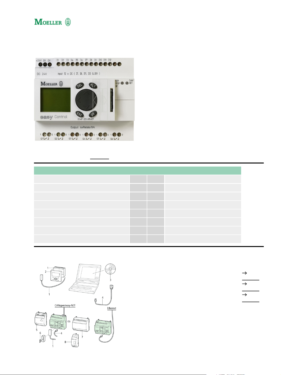
Type: EC4P−221−MRXX1
Article No.: 106394
Sales text 24 VDC,Can,12 I,6 relay
Expandable: Inputs/outputs and bus systems Individual laser inscription possible with
EC4−COMBINATION−* 107600
Ordering information
Description easy−NET/CANopen on board
Inputs
Digital 12
of which can be used as analog 4
Outputs
Relay 10 A (UL) 6
Additional features
Supply voltage 24 V DC
Notes concerning the product group
Accessories Page
1 Power supply unit/communication module
2 Display/keypad
3 Programming software
274095
265251
106407
1
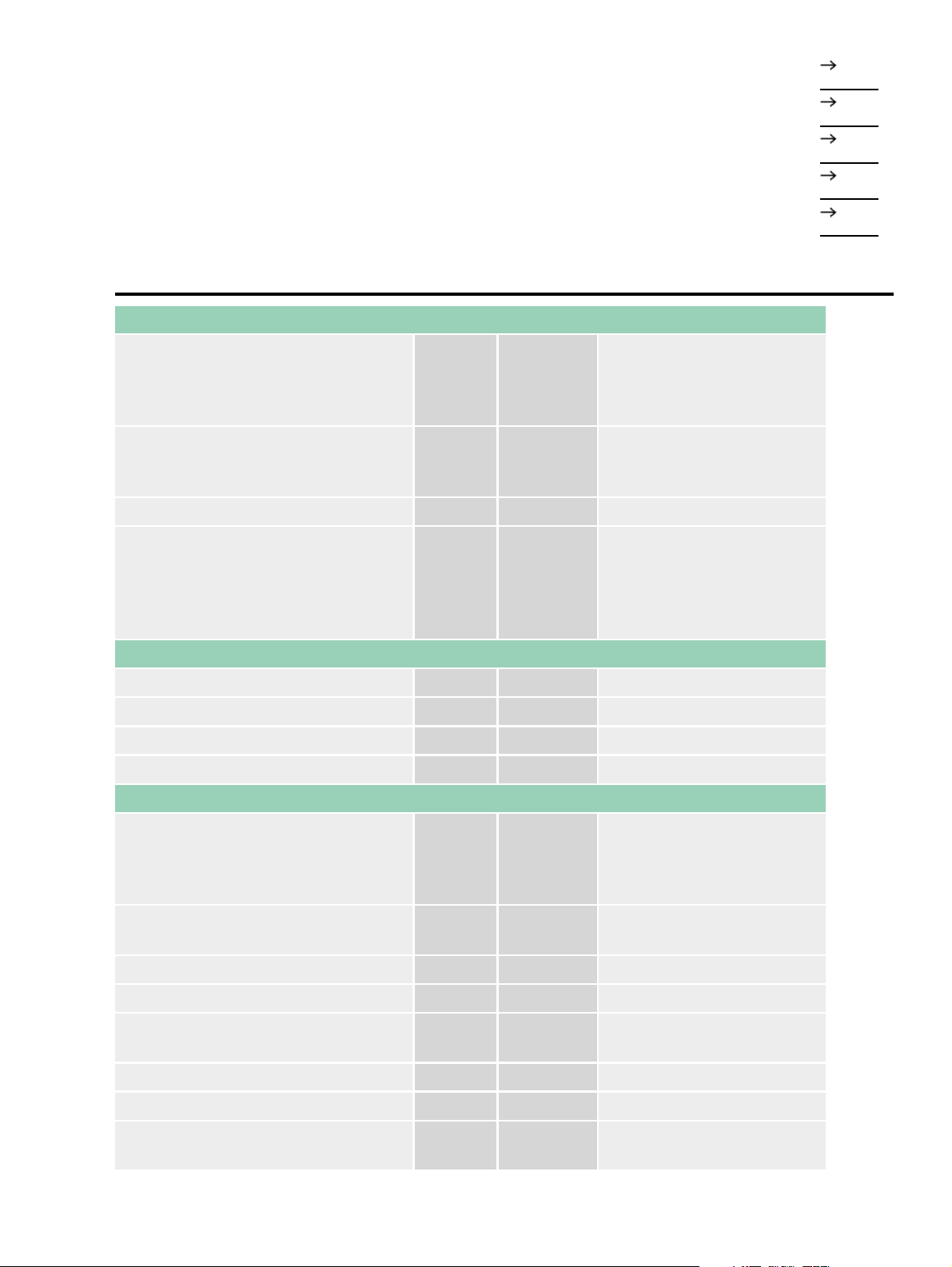
4 PC programming cable
106726
5 Switched−mode power supply unit
6 Memory card
7 I/O expansion
8 Output expansion, bus module, coupling module
General
EN 55011, EN 55022,
Standards
IEC/EN 61000−4, IEC
60068−2−6, IEC
60068−2−27
107.5 × 90 × 72 without/79
Dimensions (W × H × D) mm
with adapter for MCC (6
SU)
Weight kg 0,32
Top−hat rail IEC/EN 60715,
35 mm or screw fixing using
Mounting
3 fixing brackets
ZB4−101−GF1
(accessories)
212319
106409
212314
212315
Terminal capacities
Solid mm
Flexible with ferrule mm
2
0.2/4 (AWG 22 – 12)
2
0.2/2.5 (AWG 22 – 12)
Standard screwdriver mm 3.5 × 0.8
Max. tightening torque Nm 0,6
Climatic environmental conditions
–25 ... 55, low temperatures
Operating ambient temperature °C
to IEC 60068−2−1, high
temperatures to IEC
60068−2−2
Condensation
Take appropriate measures
to prevent condensation
LCD display (clearly legible) °C 0...55
Storage °C ... 40...+70
Relative humidity, non−condensing
(IEC/EN 60068−2−30)
% 5...95
Air pressure (operation) hPa 795...1080
Corrosion resistance
IEC/EN 60068−2−42
2
4 days
SO
2
cm3/m
3
10

IEC/EN 60068−2−43
4 days
H2S
cm3/m
3
1
Ambient conditions, mechanical
Degree of protection IEC/EN 60529 IP 20
Vibrations (IEC/EN 60068−2−6)
Constant amplitude 0.15 mm Hz 5...9
Constant acceleration 2 g Hz 8...150
Mechanical shock resistance
(IEC/EN 60068−2−27)
Impacts 18
semi−sinusoidal 15 g/11 ms
Drop to IEC/EN 60068−2−31
Free fall, packaged (IEC/EN
60068−2−32)
Drop
height
mm 50
m 1
Mounting position Horizontal/vertical
Electromagnetic compatibility (EMC)
Electrostatic discharge (IEC/EN
61000−4−2, Level 3, ESD)
Air discharge kV 8
Contact discharge kV 6
Electromagnetic fields (IEC/EN
61000−4−3, RFI)
Radio interference suppression (EN
55011)
V/m 10
EN 55011 Class B, EN
55022 Class B
Burst pulses (IEC/EN 61000−4−4,
level 3)
Supply cables kV 2
Signal lines kV 2
High−energy pulses (surge) (IEC/EN
61000−4−5)
High−energy pulses (surge) (IEC/EN
61000−4−5, level 2)
Immunity to line−conducted
interference to (IEC/EN 61000−4−6)
kV
kV
V 10
2 (supply cables,
symmetrical, EASY...AC)
0.5 symmetrical, 1
asymmetrical
Insulation resistance
Clearance in air and creepage
distances
EN 50178, UL 508, CSA
C22.2, no. 142
Insulation resistance EN 50178
Back−up/Accuracy of the real−time clock
Accuracy of the real−time clock s/day Normally ± 5 (± 0.5 hyear)
Retentive memory
Write cycles of the retentive memory
3

Power supply
10000000000 (10¹)
(Read−write cycles)
Rated operational voltage U
e
V 24 DC (−15/+20%)
Admissible range V DC 20,4...28,8
Residual ripple % 5
Input current
Input current 115/230 V AC mA Normally 140
Voltage dips (IEC/EN 61131−2) ms 10
Heat dissipation W typ.A3.4C
CPU
Microprocessor Infineon XC161
Memory
Program code/data kByte
256/14 segments of 16 KB
each
Marker/Input/Output/Retain data KByte 16/4/4/8
Cycle time for 1 k of instructions (Bit,
Byte)
ms <0,3
Interfaces
CANopen/easy−NET
500 kBit/s, 25 m 250 kBit/s,
Data transfer rate/distance
60m 125 kBit/s, 125 m 50
kBit/s, 300 m 20 kBit/s, 700
m 10 kBit/s, 1000 m
Potential isolation
From power supply Yes
From the inputs Yes
From the outputs Yes
Bus termination (first and last station)
EASY−NT−R plug (incl. bus
terminating resistor 120 )
Connection types 2 × RJ45, 8 pole
easy−NET operating mode
Number of users 8
CANopen operating mode
Stations Number max. 8
PDO type
Asynchronous, cyclic,
acyclic
Control contact rated current to DS301V4
Control voltage for remote control
max.
Digital inputs 12 V DC
4
No

Number 12
Inputs can be used as analog inputs 4 (I7, I8, I11, I12)
Status indication LCD display (if provided)
Potential isolation
From power supply No
Between digital inputs No
From the outputs Yes
Rated operational voltage Ue V DC 24
On 0 signal Ue V DC
On 1 signal Ue V DC
< 5 (I1 – I6, I9, I10) < 8 (I7,
I8, I11, I12)
> 15.0 (I1 – I6, I9, I10) > 8.0
(I7, I8, I11, I12)
Input current on 1 signal
I1 to I6 mA 3.3 (at 24 V DC)
I7, I8 mA 2.2 (at 24 V DC)
Cable length (unscreened) m 100
Pulse pause ratio 01:01
Cable length screened m < 3
Digital inputs 24 V DC
Number 12
Inputs can be used as analog inputs 4 (I7, I8, I11, I12)
Status indication LCD display (if provided)
Potential isolation
From power supply No
Between digital inputs No
From the outputs Yes
From the PC interface, memory card
NET network, EASY−Link
Yes
Rated operational voltage Ue V DC 24
On 0 signal Ue V DC
On 1 signal Ue V DC
< 5 (I1 – I6, I9, I10) < 8 (I7,
I8, I11, I12)
> 15.0 (I1 – I6, I9, I10) > 8.0
(I7, I8, I11, I12)
Input current on 1 signal
I1 to I6 mA 3.3 (at 24 V DC)
I7, I8 mA 2.2 (at 24 V DC)
I9, I10 mA 3.3 (at 24 V DC)
I11, I12 mA 2.2 (at 24 V DC)
Delay time from 0 to 1
5

Normally 0.02 (I1 – I4),
Normally 0.25 (I5 – I12)
Delay time from 1 to 0
Normally 0.02 (I1 – I4),
Normally 0.25 (I5 – I12)
Cable length (unscreened) m 100
Incremental counter
Quantity 1 (I1, I2, I3, I4)
Value range 32 Bit
Counter frequency kHz 40
Pulse shape Square
Counter inputs I1 and I2, I3 and I4 1
Counter inputs I1, I2
Reference input I3
Input for reference switch I4
Signal offset 90°
Pulse pause ratio 01:01
Rapid counter inputs
Number
2 (I1, I2) at 16 Bit or 1 (I1) at
32 Bit
Counter frequency kHz < 50
Pulse shape Square
Pulse pause ratio 01:01
Cable length, screened m < 20
Digital inputs 24 V DC
Inputs can be used as analog inputs 4 (I7, I8, I11, I12)
Status indication LCD−display (if present)
Rated operational voltage U
e
V 24 DC (−15/+20%)
Input current on 1 signal
I1 to I6 mA 3.3 (at 24 V DC)
I7, I8 mA 2.2 (at 24 V DC)
I9, I10 mA 3.3 (at 24 V DC)
I11, I12 mA 2.2 (at 24 V DC)
Digital inputs 115/230 V AC
Status indication LCD−display (if present)
Analog inputs
Quantity 4 (I7, I8, I11, I12)
Potential isolation
From power supply No
6

From the digital inputs No
From the outputs Yes
From the PC interface, memory card
NET network, EASY−Link
Yes
Input type DC voltage
Signal range V DC 0 – 10
Resolution, analog V 0,01
Resolution, digital V 0,01
Resolution, digital Bit 10 (value 0 – 1023)
Input impedance k 11,2
Accuracy of actual value
Two EASY devices % ± 3
Within a single device %
± 2, (I7, I8, I11, I12) ± 0.12
V
Conversion time, analog/digital ms Every CPU cycle
Input current mA < 1
Cable length screened m < 3
Analog outputs
Potential isolation
From power supply Yes
Conversion time, analog/digital ms Every CPU cycle
Transistor outputs
Number 8
Rated operational voltage Ue V DC 24
Admissible range U
e
V DC 20,4 – 28,8
Residual ripple % 5
Supply current
On 0 signal Normallymax. mA 18/32
On 1 signal Normallymax. mA 24/44
Yes (Attention: A
short−circuit will occur if
Protection against polarity reversal
voltage is applied to the
outputs on account of
reverse polarity.)
Potential isolation
From power supply Yes
From the inputs Yes
From the PC interface, memory card
NET network, EASY−Link
Yes
Rated operational current on 1 signal Ie A Max. 0.5
7

DC
Lamp load without R
v
Residual current on 0 signal per
channel
W 5
mA < 0,1
Max. output voltage
On 0 signal with external load < 10 M V 2,5
On 1 signal with Ie = 0.5 A V U = Ue −1 V
Yes, electronic (Q1 – Q4),
Short−circuit protection
thermal (Q5 – Q8), (analysis
via diagnostics input I16,
I15)
Short−circuit tripping current for R
10 m
a
A 0.7 Ie 2 per output
Total short−circuit current A 16
Peak short−circuit current A 32
Thermal cutout Yes
Max. operating frequency with
constant resistive load RL < 100 k
(depending on number of active
Ops./h 40000
channels and their load)
Parallel connection of outputs
With resistive load, inductive load
with external suppressor circuit,
combination within a group
Group 1: Q1 − Q4
Group 2: Q5 − Q8
Number of outputs max. 4
2 (Caution! Outputs must be
Max. total current A
actuated simultaneously
and for the same length of
time.)
Output status indication LCD−display (if present)
Inductive load
Without external suppressor circuit
T
0.95 = 1 ms, R = 48 , L = 16 mH
Utilization factor g 0,25
Duty factor % DF 100
Max. switching frequency f = 0.5 Hz
(max. DF = 50 %)
DC−13, T
0.95 = 72 ms, R = 48 , L = 1.15 H
Operations 1500
Utilization factor g 0,25
Duty factor % DF 100
Max. switching frequency f = 0.5 Hz
(max. DF = 50 %)
8
Operations 1500

T
0.95 = 15 ms, R = 48 , L = 0.24 H
Utilization factor g 0,25
Duty factor % DF 100
Max. switching frequency f = 0.5 Hz
(max. DF = 50 %)
Operations 1500
With external suppressor circuit
Utilization factor g 1
Duty factor % DF 100
Max. switching frequency, max. duty
factor
Operations
Depending on the
suppressor circuit
NET network
Stations Number max. 8
Bus termination (first and last station)
EASY−NT−R plug (incl. bus
terminating resistor 120 )
Back−up of the real−time clock
Dimensions
9

Dimensions
Moeller GmbH, Hein−Moeller−Str. 7−11, D−53115 Bonn
E−Mail: catalog@moeller.net, Internet: www.moeller.net, http://catalog.moeller.net
Copyright 2006 by Moeller GmbH. HPL−C2007G V2.1
10
 Loading...