

Type: EASY721−DC−TC
Article No.: 274121
Ordering information
Power supply V DC 24 V DC
Description
12 digital inputs (4 inputs available as analog inputs)•
8 transistor outputs•
LCD display•
Operating buttons•
Screw terminals•
Timer•
Can be expanded using easy expansion units•
Notes concerning the product group
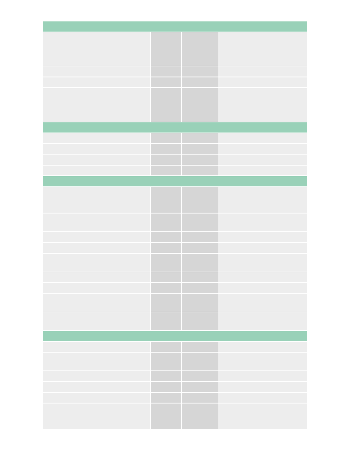
Backup of real−time clock (only for appropriate devices)
Backup time (hours)
Operating time (years)
1
General
EN 55011, EN 55022,
Standards
IEC/EN 61000−4, IEC
60068−2−6, IEC
60068−2−27
Dimensions (W × H × D) mm 107.5 × 90 × 58 (6 PE)
Weight kg 0,3
Top−hat rail IEC/EN 60715,
Mounting
35 mm or screw fixing using
fixing brackets
ZB4−101−GF1 (accessories)
Terminal capacities
Solid mm
Flexible with ferrule mm
2
0.24 (AWG 22 – 12)
2
0.22.5 (AWG 22 – 12)
Standard screwdriver mm 3.5 × 0.8
Max. tightening torque Nm 0,6
Climatic environmental conditions
−25 to 55, cold as per IEC
Operating ambient temperature °C
60068−2−1, heat as per IEC
60068−2−2
Condensation
Take appropriate measures
to prevent condensation
LCD display (clearly legible) °C 055
Storage °C −40/+70
Relative humidity, non−condensing
(IEC/EN 60068−2−30)
% 5 – 95
Air pressure (operation) hPa 795 – 1080
Corrosion resistance
IEC/EN 60068−2−42
IEC/EN 60068−2−43
4 days
SO
2
4 days
H2S
cm3/m
cm3/m
3
10
3
1
Ambient conditions, mechanical
Pollution degree 2
Degree of protection (IEC/EN
60529)
IP 20
Vibrations (IEC/EN 60068−2−6)
Constant amplitude 0.15 mm Hz 10 – 57
Constant acceleration 2 g Hz 57 – 150
Mechanical shock resistance
(IEC/EN 60068−2−27)
Impacts 18
semi−sinusoidal 15 g/11 ms
2
Drop to IEC/EN 60068−2−31
Drop
height
mm 50
Free fall, packaged (IEC/EN
60068−2−32)
m 1
Mounting position horizontal/vertical
Electromagnetic compatibility (EMC)
Electrostatic discharge (IEC/EN
61000−4−2, Level 3, ESD)
Air discharge kV 8
Contact discharge kV 6
Electromagnetic fields (IEC/EN
61000−4−3, RFI)
Radio interference suppression (EN
55011)
V/m 10
EN 55011 Class B, EN
55022 Class B
Burst pulses (IEC/EN 61000−4−4,
level 3)
Supply cables kV 2
Signal lines kV 2
High−energy pulses (surge)
(IEC/EN 61000−4−5)
kV
2 (supply cables,
symmetrical, EASY...AC)
High−energy pulses (surge)
(IEC/EN 61000−4−5, level 2)
kV
0.5 (supply cables,
symmetrical, EASY...DC)
Immunity to line−conducted
interference to (IEC/EN
V 10
61000−4−6)
Insulation resistance
Clearance in air and creepage
distances
EN 50178, UL 508, CSA
C22.2, no. 142
Insulation resistance EN 50178
Backup/accuracy of the real−time clock
Accuracy of the real−time clock Normally ± 5 (± 0.5 hyear)
Repetition accuracy of timing relays
Accuracy of timing relays (of
values)
% ± 1
Resolution
Range “S” ms 10
Range “M:S” s 1
Range “H:M” min 1
Retentive memory
Write cycles of the retentive
memory
Power supply
3
1000000 (106)

Rated operational voltage U
e
V 24 DC (−15/+20%)
Admissible range V DC 20,4 – 28,8
Residual ripple % 5
Input current
Input current 115/230 V AC mA Normally 140
Voltage dips (IEC/EN 61131−2) ms 10
Heat dissipation W Normally 3.5
Digital inputs 24 V DC
Number 12
Inputs can be used as analog
inputs
4 (I7, I8, I11, I12)
Status indication LCD−display (if present)
Potential isolation
From power supply No
Between digital inputs No
From the outputs Yes
Rated operational voltage U
On 0 signal U
On 1 signal U
e
e
e
V DC 24
V DC < 5 (I1 – I12, R1 – R12)
V DC
> 15.0 (I1 – I6, I9, I10), > 8.0
(I7, I8, I11, I12)
Input current on 1 signal
I1 to I6 mA 3.3 (at 24 V DC)
I7, I8 mA 2.2 (at 24 V DC)
I9, I10 mA 3.3 (at 24 V DC)
I11, I12 mA 2.2 (at 24 V DC)
Delay time from 0 to 1
Debounce ON ms 20
Debounce OFF ms Normally 0.25 (I1 – I12)
Delay time from 1 to 0
Debounce ON ms 20
Cable length (unscreened) m 100
Frequency counter
Quantity 2 (I3, I4)
Counter frequency kHz < 1
Pulse shape Square
Pulse pause ratio 1:1
Rapid counter inputs
Number 2 (I1, I2)
Counter frequency kHz < 1
4

Pulse shape Square
Pulse pause ratio 1:1
Analog inputs
Quantity 4 (I7, I8, I11, I12)
Potential isolation
From power supply No
From the digital inputs No
From the outputs Yes
From the PC interface, memory
card NET network, EASY−Link
No
Input type DC voltage
Signal range V DC 0 – 10
Resolution, analog V 0,01
Resolution, digital V 0,01
Resolution, digital Bit 10 (value 0 – 1023)
Input impedance k 11,2
Accuracy of actual value
Two EASY devices % ± 3
Within a single device % ± 2, ± 0.12 V
Debounce ON: 20;
Conversion time, analog/digital ms
Debounce OFF: every cycle
time
Input current mA < 1
Cable length screened m < 30
Transistor outputs
Number 8
Rated operational voltage U
Admissible range U
e
e
V DC 24
V DC 20,4 – 28,8
Residual ripple % 5
Supply current
On 0 signal Normallymax. mA 1832
On 1 signal Normallymax. mA 24 – 44
Yes (Attention: A
short−circuit will occur if
Protection against polarity reversal
voltage is applied to the
outputs on account of
reverse polarity.)
Potential isolation
From power supply Yes
Potential isolation Yes
5

Rated operational current on 1
signal DC
I
e
A Max. 0.5
Lamp load without R
v
Residual current on 0 signal per
channel
W 5
mA < 0,1
Max. output voltage
On 0 signal with external load < 10
M
V 2,5
On 1 signal with Ie = 0.5 A V U = Ue −1 V
Yes, thermal (analysis via
Short−circuit protection
diagnostics input I16, I15;
R15, R16)
Short−circuit tripping current for R
10 m
a
A 0.7 Ie 2 per output
Total short−circuit current A 16
Peak short−circuit current A 32
Thermal cutout Yes
Max. operating frequency with
constant resistive load RL < 100 k
(depending on number of active
Ops./h 40000
channels and their load)
Parallel connection of outputs
With resistive load, inductive load
with external suppressor circuit,
combination within a group
Group 1: Q1 to Q4
Group 2: Q5 − Q8
Number of outputs max. 4
2 (Caution! Outputs must be
Max. total current
actuated simultaneously and
for the same length of time.)
Output status indication LCD−display (if present)
Inductive load
Without external suppressor circuit
T
0.95 = 1 ms, R = 48 , L = 16 mH
Utilization factor g 0,25
Duty factor % DF 100
Max. switching frequency f = 0.5 Hz
(max. DF = 50 %)
DC−13,
T0.95 = 72 ms, R = 48 , L = 1.15 H
Operations 1500
Utilization factor g 0,25
Duty factor % DF 100
Max. switching frequency f = 0.5 Hz
(max. DF = 50 %)
6
Operations 1500

T
0.95 = 15 ms, R = 48 , L = 0.24 H
Utilization factor g 0,25
Duty factor % DF 100
Max. switching frequency f = 0.5 Hz
(max. DF = 50 %)
Operations 1500
With external suppressor circuit
Utilization factor g 1
Duty factor % DF 100
Max. switching frequency, max.
duty factor
Operations
Depending on the
suppressor circuit
Analog outputs
Potential isolation
From power supply No
From the digital inputs No
Signal range V DC 0 – 10
Debounce ON: 20;
Conversion time, analog/digital ms
Debounce OFF: every cycle
time
Notes
Dimensions
Notes
For additional Technical Data EASY5... and EASY7... AWB2528−1508GB,
EASY8... AWB2528−1423D
Notes
For inductive loading, without external suppression of the transistor outputs, the following applies:
T
= time in ms, until 95 % of the steady−state current is achieved. T
0.95
0.95
3 × T
= 3 × L/R.
0.65
Data transfer rate in the NET network: bus lengths of 40 m and over only attainable with cables with
additional cross−section and connection adapter.
Dimensions
7

Moeller GmbH, Hein−Moeller−Str. 7−11, D−53115 Bonn
E−Mail: catalog@moeller.net, Internet: www.moeller.net, http://catalog.moeller.net
Copyright 2006 by Moeller GmbH. Subject to modifications. HPL−C2006GB−INT V2.3
8
 Loading...