

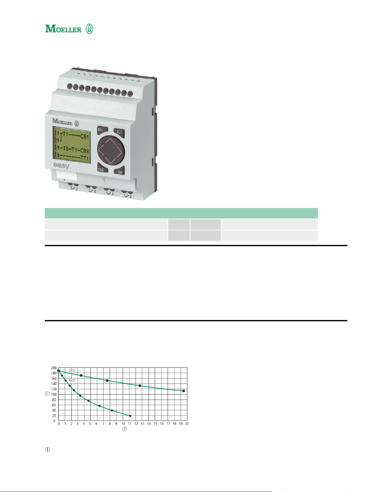
Type: EASY512−DC−RC
Article No.: 274109
Ordering information
Relay outputs Quantity 4
Power supply V DC 24 V DC
Description
8 digital inputs (2 inputs available as analog inputs)•
4 relay outputs•
LCD display•
Operating buttons•
Screw terminals•
Timer•
Notes concerning the product group
Backup of real−time clock (only for appropriate devices)
Backup time (hours)
1
Operating time (years)
General
EN 55011, EN 55022,
Standards
IEC/EN 61000−4, IEC
60068−2−6, IEC
60068−2−27
Dimensions (W × H × D) mm 71.5 × 90 × 58 (4 PE)
Weight kg 0,2
Top−hat rail IEC/EN 60715,
Mounting
35 mm or screw fixing using
fixing brackets
ZB4−101−GF1 (accessories)
Terminal capacities
Solid mm20.24 (AWG 22 – 12)
Flexible with ferrule mm20.22.5 (AWG 22 – 12)
Standard screwdriver mm 3.5 × 0.8
Max. tightening torque Nm 0,6
Climatic environmental conditions
−25 to 55, cold as per IEC
Operating ambient temperature °C
60068−2−1, heat as per IEC
60068−2−2
Condensation
Take appropriate measures
to prevent condensation
LCD display (clearly legible) °C 055
Storage °C −40/+70
Relative humidity, non−condensing
(IEC/EN 60068−2−30)
% 5 – 95
Air pressure (operation) hPa 795 – 1080
Corrosion resistance
IEC/EN 60068−2−42 4 days SO2cm3/m310
IEC/EN 60068−2−43 4 days H2S cm3/m31
Ambient conditions, mechanical
Pollution degree 2
Degree of protection (IEC/EN
60529)
IP 20
Vibrations (IEC/EN 60068−2−6)
Constant amplitude 0.15 mm Hz 10 – 57
Constant acceleration 2 g Hz 57 – 150
Mechanical shock resistance
(IEC/EN 60068−2−27)
Impacts 18
semi−sinusoidal 15 g/11 ms
2
Drop to IEC/EN 60068−2−31 Drop height mm 50
Free fall, packaged (IEC/EN
60068−2−32)
m 1
Mounting position horizontal/vertical
Electromagnetic compatibility (EMC)
Electrostatic discharge (IEC/EN
61000−4−2, Level 3, ESD)
Air discharge kV 8
Contact discharge kV 6
Electromagnetic fields (IEC/EN
61000−4−3, RFI)
Radio interference suppression (EN
55011)
V/m 10
EN 55011 Class B, EN
55022 Class B
Burst pulses (IEC/EN 61000−4−4,
level 3)
Supply cables kV 2
Signal lines kV 2
High−energy pulses (surge) (IEC/EN
61000−4−5)
kV
2 (supply cables,
symmetrical, EASY...AC)
High−energy pulses (surge) (IEC/EN
61000−4−5, level 2)
Immunity to line−conducted
interference to (IEC/EN 61000−4−6)
kV
0.5 (supply cables,
symmetrical, EASY...DC)
V 10
Insulation resistance
Clearance in air and creepage
distances
EN 50178, UL 508, CSA
C22.2, no. 142
Insulation resistance EN 50178
Backup/accuracy of the real−time clock
Accuracy of the real−time clock typ. ± 5 (± 0.5 hannually)
Repetition accuracy of timing relays
Accuracy of timing relays (of values) % ± 1
Resolution
Range “S” ms 10
Range “M:S” s 1
Range “H:M” min 1
Retentive memory
Write cycles of the retentive memory 1000000 (106)
Power supply
Rated operational voltage U
e
V 24 DC (−15/+20%)
Admissible range V DC 20,4 – 28,8
Residual ripple % 5
3
Input current
Input current 115/230 V AC mA Normally 80
Voltage dips (IEC/EN 61131−2) ms 10
Heat dissipation W Normally 2
Digital inputs 24 V DC
Number 8
Inputs can be used as analog inputs 2 (I7, I8)
Status indication LCD−display (if present)
Potential isolation
From power supply No
Between digital inputs No
From the outputs Yes
Rated operational voltage U
On 0 signal U
On 1 signal U
e
e
e
V DC 24
V DC < 5 (I1 – I8)
V DC > 15 (I1 – I6), > 8 (I7, I8)
Input current on 1 signal
I1 to I6 mA 3.3 (at 24 V DC)
I7, I8 mA 2.2 (at 24 V DC)
Delay time from 0 to 1
Debounce ON ms 20
Debounce OFF ms Normally 0.25 (I1 – I8)
Delay time from 1 to 0
Debounce ON ms 20
Cable length (unscreened) m 100
Frequency counter
Quantity 2 (I3, I4)
Counter frequency kHz < 1
Pulse shape Square
Pulse pause ratio 1:1
Rapid counter inputs
Number 2 (I1, I2)
Counter frequency kHz < 1
Pulse shape Square
Pulse pause ratio 1:1
Analog inputs
Quantity 2 (I7, I8)
Potential isolation
From power supply No
4

From the digital inputs No
From the outputs Yes
From the PC interface, memory card
NET network, EASY−Link
No
Input type DC voltage
Signal range V DC 0 – 10
Resolution, analog V 0,01
Resolution, digital V 0,01
Resolution, digital Bit 10 (value 1 – 1023)
Input impedance k 11,2
Accuracy of actual value
Two EASY devices % ± 3
Within a single device % ± 2, ± 0.12 V
Debounce ON: 20;
Conversion time, analog/digital ms
Debounce OFF: every cycle
time
Input current mA < 1
Cable length screened m < 30
Relay outputs
Number 4
Outputs in groups of 1
Parallel switching of outputs for
increased output
Protection of an output relay
Not permissible
Miniature circuit−breaker B16
or fuse 8 A (slow)
Potential isolation
From power supply Yes
From the inputs Yes
From the PC interface, memory card
NET network, EASY−Link
No
Safe isolation V AC 300
Basic insulation V AC 600
Lifespan, mechanical Operations × 10610
Contacts
Conventional thermal current (10 A
UL)
Recommended for load: 12 V
AC/DC
A 8
mA > 500
Short−circuit−proof cos = 1,
characteristic B16 at 600 A
5
A 16
A 16

Short−circuit−proof cos = 0.5 to 0.7,
characteristic B16 at 900 A
Rated impulse withstand voltage
U
of contact coil
imp
Rated operational voltage U
Rated insulation voltage U
Safe isolation to EN 50178 between
coil and contact
Safe isolation to EN 50178 between
2 contacts
e
i
kV 6
V AC 250
V AC 250
V AC 300
V AC 300
Making capacity
AC−15, 250 V AC, 3 A (600 Ops./h) Operations 300000
DC−13 L/R 150 ms 24 V DC, 1 A
(500 Ops./h)
Operations 200000
Breaking capacity
AC−15, 250 V AC, 3 A (600 Ops./h) Operations 300000
DC−13 L/R 150 ms 24 V DC, 1 A
(500 Ops./h)
Operations 200000
Filament bulb load
1000 W at 230/240 V AC Operations 25000
500 W at 115/120 V AC Operations 25000
Fluorescent lamp load
Fluorescent lamp load 10 × 58 W at
230/240 V AC
With upstream electrical device Operations 25000
Uncompensated Operations 25000
Fluorescent lamp load 1 × 58 W at
230/240 V AC, conventional,
Operations 25000
compensated
Switching frequency
Mechanical operations × 10610
Switching frequency Hz 10
Resistive load/lamp load Hz 2
Inductive load Hz 0,5
UL/CSA
Uninterrupted current at 240 V AC A 10
Uninterrupted current at 24 V DC A 8
AC
Control Circuit Rating Codes
(utilization category)
B 300 Light Pilot Duty
Max. rated operational voltage V AC 300
6

Max. thermal uninterrupted current
= 1 at B 300
A 5
Max. make/break capacity 1 at B
300
VA 3600360
DC
Control Circuit Rating Codes
(utilization category)
R 300 Light Pilot Duty
Max. rated operational voltage V DC 300
Max. thermal uninterrupted current
at R 300
A 1
Max. make/break capacity at R 300 VA 2828
Analog outputs
Potential isolation
From power supply No
From the digital inputs No
Signal range V DC 0 – 10
Debounce ON: 20;
Conversion time, analog/digital ms
Debounce OFF: every cycle
time
Notes
Dimensions
Notes
For additional Technical Data EASY5... and EASY7... AWB2528−1508GB,
EASY8... AWB2528−1423D
Dimensions
7

Moeller GmbH, Hein−Moeller−Str. 7−11, D−53115 Bonn
E−Mail: catalog@moeller.net, Internet: www.moeller.net, http://catalog.moeller.net
Copyright 2006 by Moeller GmbH. Subject to modifications. HPL−C2006GB−INT V2.3
8
 Loading...