

Moeller EASY 412-DC-RC, EASY 412-AC Series, EASY 618-AC-RC, EASY 412-DC-TCX, EASY 412-DC-TC Training Manual
...Page 1

Training Guide
For Immediate Delivery call KMParts.com at (866) 595-9616
EASY 412-DC-... EASY 618-AC-RC
EASY 412-AC-... EASY 620-DC-TC
Control Relay
06/99 AWB 2528-1316 GB
1st published 1998, edition 04/98
2nd published 1999, edition 06/99
see list of revisions on page II
© Moeller GmbH, Bonn
Author: Dieter Bauerfeind
Editor: Jörg Eiserloh, Thomas Kracht
Translator: Terence Osborn
Page 2

Caution!
For Immediate Delivery call KMParts.com at (866) 595-9616
Dangerous electrical voltage!
Before commencing the installation
● Disconnect the power supply of the
device.
● Ensure that the device cannot be
accidentally restarted.
● Verify isolation from the supply.
● Earth and short circuit.
● Cover or enclose neighbouring units that
are live.
● Follow the engineering instructions
(AWA) of the device concerned.
● Only suitably qualified personnel may
work on this device/system.
● Before installation and before touching
the device ensure that you are free of
electrostatic charge.
● Connecting cables and signal lines
should be installed so that inductive or
capacitive interference do not impair the
automation functions.
● Install automation devices and related
operating elements in such a way that
they are well protected against
unintentional operation.
● Suitable safety hardware and software
measures should be implemented for
the I/O interface so that a line or wire
breakage on the signal side does not
result in undefined states in the
automation devices.
● Ensure a reliable electrical isolation of
the low voltage for the 24 volt supply.
Only use power supply units complying
with IEC 60 364-4-41 or HD 384.4.41 S2.
● Deviations of the mains voltage from the
rated value must not exceed the
tolerance limits given in the
specifications, otherwise this may cause
malfunction and dangerous operation.
● Emergency stop devices complying with
IEC/EN 60 204-1 must be effective in all
operating modes of the automation
devices. Unlatching the emergency-stop
devices must not cause uncontrolled
operation or restart.
● Devices that are designed for mounting
in housings or control cabinets must only
be operated and controlled after they
have been installed with the housing
closed. Desktop or portable units must
only be operated and controlled in
enclosed housings.
● Measures should be taken to ensure the
proper restart of programs interrupted
after a voltage dip or failure. This should
not cause dangerous operating states
even for a short time. If necessary,
emergency-stop devices should be
implemented.
IBM is a registered trademark of International
Business Machines Corporation.
All other brand and product names are
trademarks or registered trademarks of the
owner concerned.
All rights reserved, including those of the
translation.
No part of this manual may be reproduced in
any form (printed, photocopy, microfilm or
any otherprocess) or processed, duplicated
or distributed by means of electronic
systems without written permission of
Moeller GmbH, Bonn.
Subject to alterations without notice.
Page 3

List of revisions for the manual AWB 2528-1316 GB
For Immediate Delivery call KMParts.com at (866) 595-9616
Edition Page Title New Modified Omitted
06/99 gen. EASY 620-DC-TC
EASY 618-AC-RC
4Functions ҂
5 “easy” at a glance ҂
6Mounting ҂
6 ff. Connecting “easy” ҂
12 EASY 6... status display ҂
14,
23 ff.
16 System menu ҂
20 Menu languages ҂
22 Startup behaviour ҂
36 Text display (markers) ҂
44 Available memory cards ҂
44 EASY-SOFT ҂
45 Technical data ҂
47 Dimensions of EASY 6... ҂
Circuit diagram elements ҂
҂
II
06/99 AWB 2528-1316 GB
Page 4

Contents
For Immediate Delivery call KMParts.com at (866) 595-9616
1 “easy” Control Relay
Simply “easy” 3
Mounting “easy” 6
Connecting “easy” 6
“easy” operating principle 11
2 Drawing a Circuit with “easy”
Operation of “easy” 19
Setting the menu language 20
Setting the time 21
Choose “easy” operating mode 22
“easy”-Circuit diagram elements 23
Example: creating a circuit diagram 26
Function relay types 30
Example: using a function relay 37
Basic circuits 41
3 “easy” Interface Socket
4 Technical Data
Technical data 45
“easy” models 45
3
19
43
45
Index
06/99 AWB 2528-1316 GB
49
1
Page 5

Contents
For Immediate Delivery call KMParts.com at (866) 595-9616
2
06/99 AWB 2528-1316 GB
Page 6
1 “easy” Control Relay
For Immediate Delivery call KMParts.com at (866) 595-9616
Safety information
Danger of injury due to electric shock!
The electrical installation and commissioning
work must only be carried out by suitably
qualified personnel.
Do not work on the device when the power is
switched on.
Observe the relevant safety regulations:
Switch off the power
Make sure that the device cannot be
switched on again inadvertently
Check to make sure that no dangerous
voltages are present before working on the
device
Cover up any neighbouring equipment which
carries dangerous voltages
Simply “easy” Clever switching and controlling
“easy” is a compact, user-friendly and low-cost
control relay for simple control applications.
Applications range from building and domestic
automation to machine and plant control. “easy” has
built-in user-friendly operating elements and an LCD
display.
Just connect up “easy” and draw your circuit
diagram on the display by pressing the buttons on
the device. “easy” works with make contacts, break
contacts, and relays.
06/99 AWB 2528-1316 GB
3
Page 7

“easy” Control Relay
For Immediate Delivery call KMParts.com at (866) 595-9616
Enter your circuit diagram in “easy” just like you
sketched it on paper. “easy” has basic and advanced
functions for relays, time switches and contactors,
and lots more, too. You can make changes to your
circuit just by pressing the buttons on the device.
Time consuming rewiring is not necessary.
Applications everywhere
Building and domestic automation, controllers for
lighting, doors, window shutters...
Control ventilators, rotating doors, greenhouses,
exterior lighting, window controllers, shop display
lighting control...
Create controllers for temperature, ventilation and
brightness levels...
Control machines and plant, presses, conveyor
belts, oscillating conveyors, sorters, pumps...
Additional functions
With the help of the additional 600 units EASY 620-DC-TC, EASY 618-AC-RC - as well as the
expansion of the 400 range with EASY 412-DC-TC,
EASY 412-DC-TCX and EASY 412-AC-RCX,
additional I/O and functions are now available, such
as retentive counters, timing relays, markers and
eight user-definable display texts.
The individual features of each control relay are
described below.
4
06/99 AWB 2528-1316 GB
Page 8
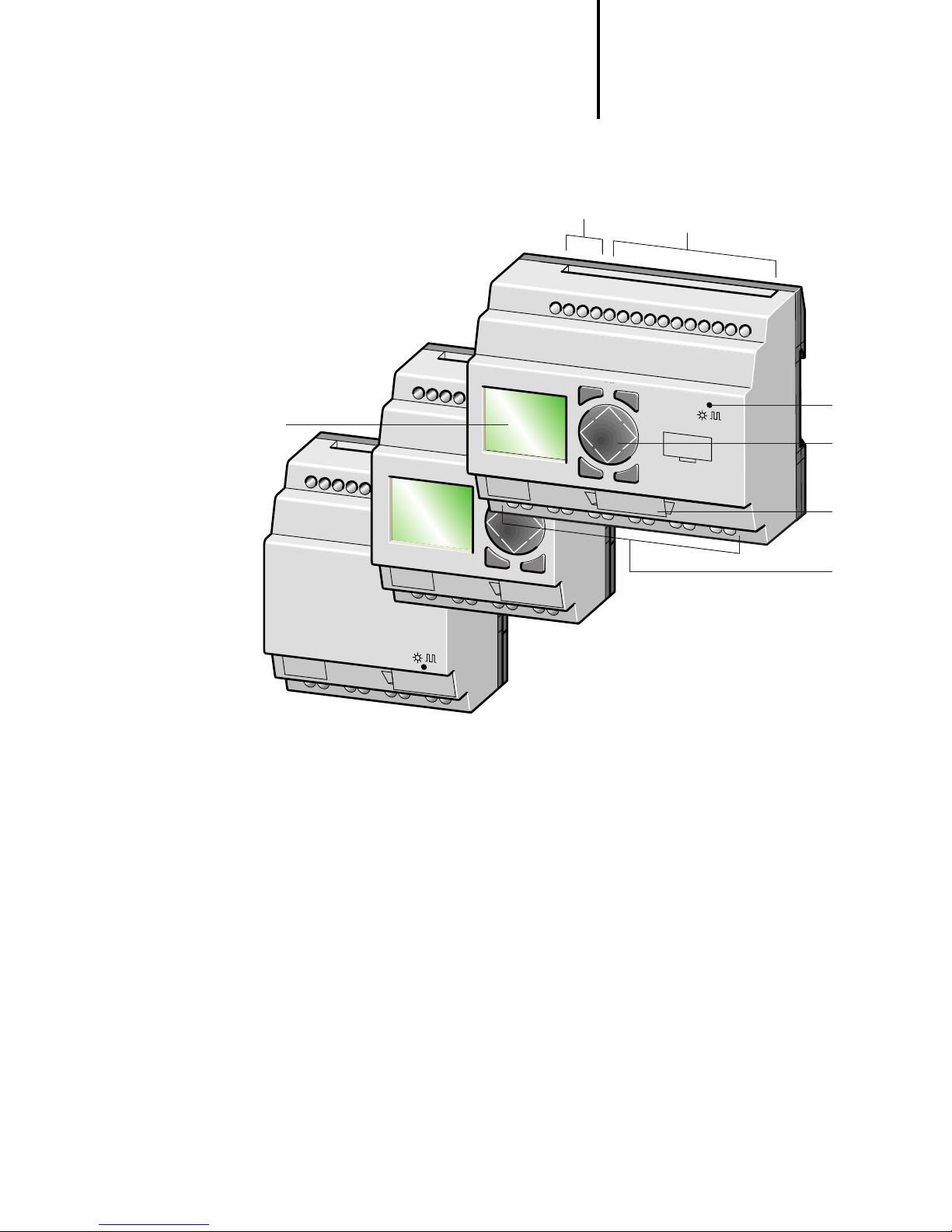
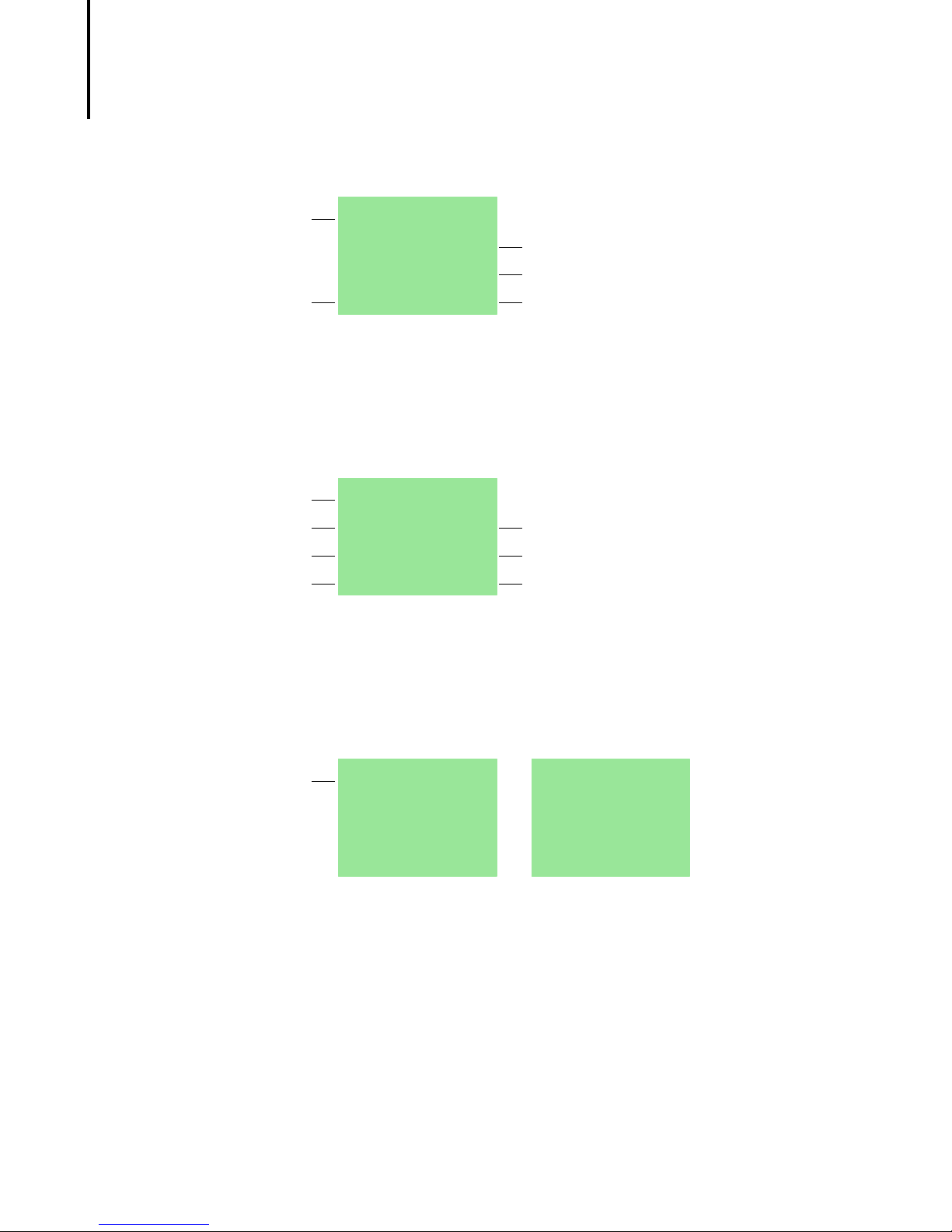
Overview of “easy”
For Immediate Delivery call KMParts.com at (866) 595-9616
Simply “easy”
g
a
b
DEL
ALT
c
d
ESC
DEL
ALT
OK
e
ESC
OK
f
06/99 AWB 2528-1316 GB
a Power supply
b Inputs
c Buttons
d Socket for memory card or PC interface cable
e Output terminals
f LCD display
5
Page 9
“easy” Control Relay
1.
2.
For Immediate Delivery call KMParts.com at (866) 595-9616
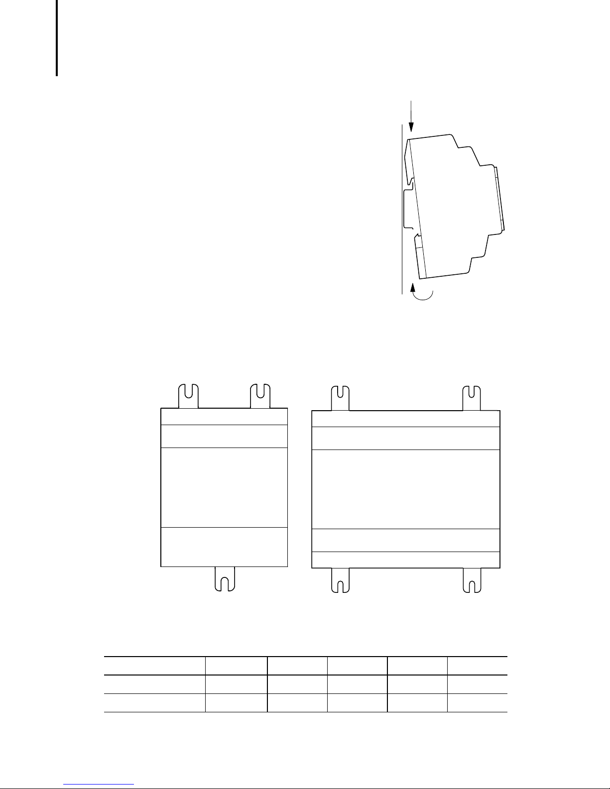
Mounting “easy” Mounting on top-hat rail
Hook “easy” to the top edge
of the top-hat rail and hinge
into place while pressing
down slightly as shown by the
arrows.
“easy” will clip into place and
will be secured by the built-in
spring mechanism without
needing screws.
Mounting on a mounting plate
“easy” can be screwed to a mounting plate with the
three device feet (available as an optional accessory).
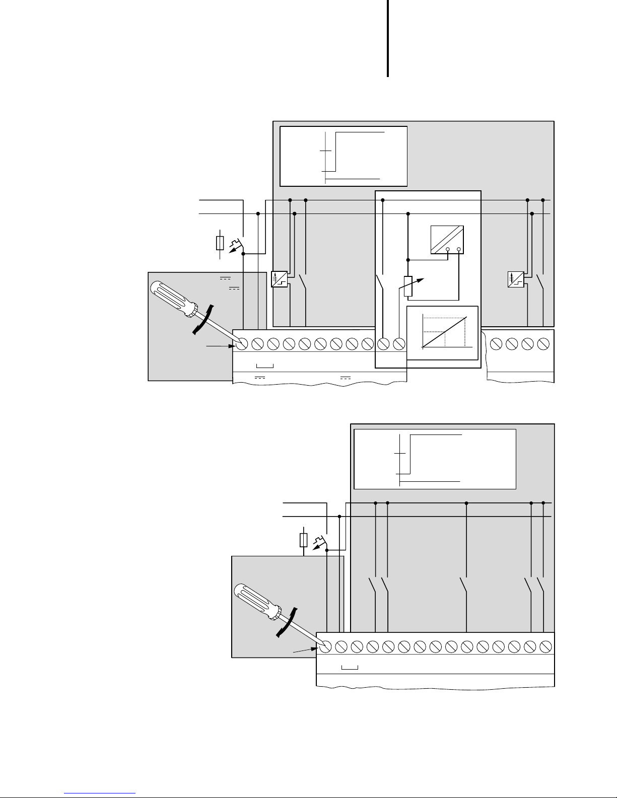
Connecting “easy” Overview
EASY... 412-DC-R... 412-DC-TC 412 AC-R... 618-AC-RC 620-DC-TC
Connecting inputs Page 7 Page 7 Page 7 Page 9 Page 9
Connecting outputs Page 8 Page 8 Page 8 Page 10 Page 10
6
06/99 AWB 2528-1316 GB
Page 10
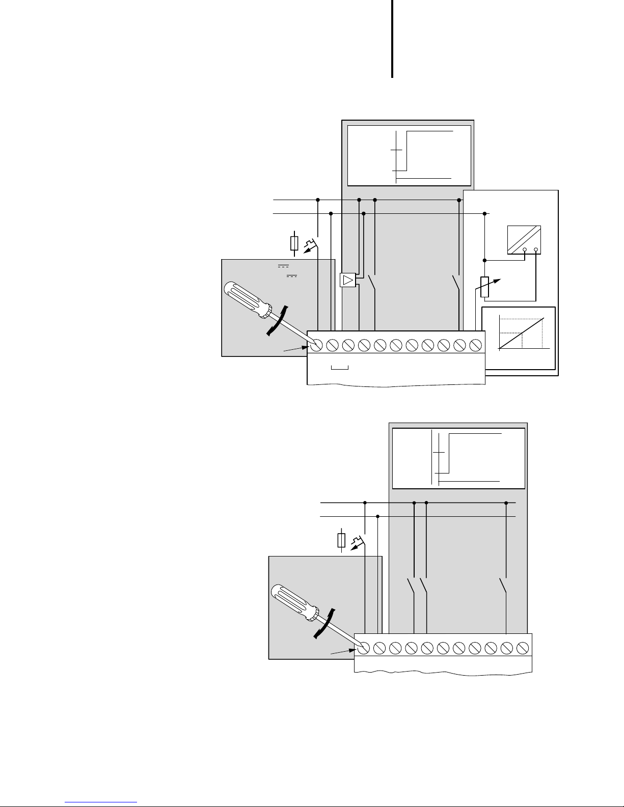
Inputs EASY 412-DC-...
For Immediate Delivery call KMParts.com at (866) 595-9616
1 ⭌ 15 V
0 ⬉ 5 V
Connecting “easy”
l = 2 mA/24 V
I7, I8 = 2.2 mA/24 V
Ue = 24 V
(20.4–28.8 V )
Ie = 80 mA
⬉ 0.5 Nm
+24 V
0 V
> 1 A
3.5 mm
+24 V
0 V
0 V
l1
I2
Inputs EASY 412-AC-...
I3
1 ⭌ 79 V
0 ⬉ 40 V
I4 I5
264 V
10 V
5 V
0 V
I6
I7 I8
l1–I6 = 0.5 mA 230 V
l1–I6 = 0.25 mA 115 V
I7, I8
l = 6 mA 230 V
l = 4 mA 115 V
l7, l8
0
˜
0 V
+10 V
510
06/99 AWB 2528-1316 GB
⬉ 0.5 Nm
L
N
> 1 A
Ue = 115/230 V ⵑ
50/60 Hz
(97–264 V ⵑ)
le = 40 mA 115 V
20 mA 230 V
3.5 mm
NL
N
l1
I2
I4 I5
I3
I6
I7 I8
7
Page 11
“easy” Control Relay
0 V
Q..
+ 24 V
U ⬉ 33 V
z
0 V
Q..
For Immediate Delivery call KMParts.com at (866) 595-9616
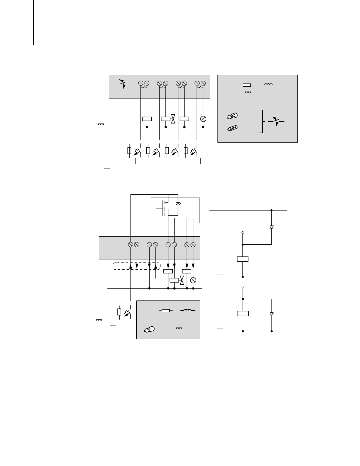
Outputs EASY 412-AC-..., EASY 412-DC-R...
⬉ 10 000 000
0 V , N
⬉ 8 A/B 16
L1, L2, L3 (115/230 V ⵑ)
+ 24 V
Outputs EASY 412-DC-T...
+24 V
1
2
1
Q1
+24 V
Q2
0 V 0 V Q1 Q2 Q3 Q4
1
2
Q3 Q4
2
2
1
R
24 V 8 A
115 V ⵑ 8 A
230 V ⵑ 8 A
1000 W
10 ⫻ 58 W
L
2 A
2 A
2 A
⬉ 25.000
Suppressor circuit
0 V
⭌ 2.5 A
+ 24 V
20.4–28.8 V
⬉10 A
24 V
R
0.5 A
5 W/24 V
L
0.5 A
8
06/99 AWB 2528-1316 GB
Page 12
Inputs EASY 620-DC-TC
For Immediate Delivery call KMParts.com at (866) 595-9616
Connecting “easy”
⬉ 0.5 Nm
+24 V
0V
> 1 A
Ue = 24 V
(20.4–28.8 V )
= 140 mA
I
e
3.5 mm
I1–I6, I9–I12 = 3.3 mA
24 V
I7, I8 = 2.2 mA
24 V
I4 I5
I3
Input 24 V
+24 V
24 V
0V
0V
28.8 V
1 ⭌ 15 V
0 ⬉ 5 V
l1
I2
Inputs EASY 618-AC-RC
l7, I8
I6
I7 I8
10 V
5V
0V
0
ⵑ
0V
50 100
+10 V
I9
I10
I11 I12
⬉ 0.5 Nm
L
N
> 1 A
Ue = 115/230 V ⵑ
50/60 Hz
(85–264 V ⵑ)
le = 70 mA 115 V
35 mA 230 V
3.5 mm
264 V
1 ⭌ 79 V
0 ⬉ 40 V
NL
N
l1
115/230 V ⵑ Input 115/230 V ⵑ
l1–I6, I9 –I12 = 0.5 mA 230 V
l1–I6, I9 –I12 = 0.25 mA 115 V
I7, I8
l = 6 mA 230 V
l = 4 mA 115 V
I4 I5
I3
I2
I9
I6
I7 I8
I10
I11 I12
06/99 AWB 2528-1316 GB
9
Page 13
“easy” Control Relay
0 V
Q..
+ 24 V
U ⬉ 33 V
z
0 V
Q..
For Immediate Delivery call KMParts.com at (866) 595-9616
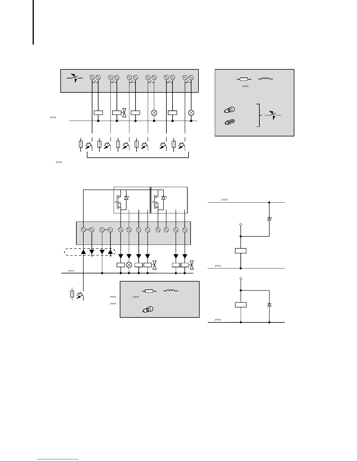
Outputs EASY 618-AC-RC
⬉ 10 000 000
0 V ,N
⬉
8 A/B 16
L1, L2, L3 (115/230 V ⵑ)
+ 24 V
12 2 2 2 2 2
Q1
1
Q2
1
1
1
Outputs EASY 620-DC-TC
+24 V 0 V Q1 Q2 Q3
Q4
Q5
Q6
Q7
1
Q6Q5Q4Q3
R
24 V
115 V ⵑ 8 A
230 V ⵑ 8A
8A
1000 W
10 ⫻ 58 W
2A
2A
2A
⬉ 25.000
Suppressor circuit
Q8
0 V
⭌ 2.5 A
⬉10 A
+ 24 V
(20.4–28.8 V )
24 V
R
0.5 A
0.5
5 W/24 V
10
06/99 AWB 2528-1316 GB
Page 14
“easy” operating principle
For Immediate Delivery call KMParts.com at (866) 595-9616
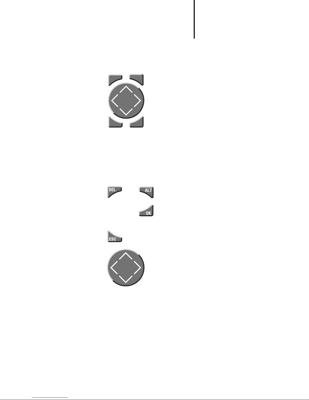
“easy” operating
principle
DELDELDELDELDELDELDELDELDELDEL
ESC
“easy” operating buttons
: Delete object in the circuit diagram
AL T
DEL
: Special functions in the circuit
ALT
diagram
Cursor buttons
:
ÍÚ
úí
Move cursor,
Select menu item,
OK
Choose contact numbers, values, time etc.
: Next menu level, store your entry
OK
: Last menu level, cancel your entry
ESC
Moving through menus and choosing values
Show system menu
and
Go to next menu level
Select menu item
Store your entry
Return to last menu level
Cancel your entry since the last
ÍÚ
Change menu item
Change value
úí
Change position
P button function (if enabled):
ú
í
Input P1,
Input P3,
Í
Input P2
Ú
Input P4
OK
06/99 AWB 2528-1316 GB
11
Page 15
“easy” Control Relay
For Immediate Delivery call KMParts.com at (866) 595-9616
EASY 412-...status display
Inputs
Output
I12345678
ââ###### MO
â### 12:50
Q1234 RUN
Weekday
Time
RUN/STOP mode
terminals
â
On/ # Off
Status displayEASY 618-..., EASY 620-...
Inputs
Retention Debounce/P buttons
Day, time Stop mode
Output
1...5..8....
RE I P
MO 02:00 ST
.2..5..8 RUN
Mode
terminals
1, 2, 5, 8 On/.Off
12
Current choice
blinks in the
“easy” menu
Menu display
PROGRAM...
PROGRAM..
PARAMETER
SET CLOCK..
PASSWORD..
PROGRAM..
PARAMETER
SET CLOCK..
Main menu with and without password option
06/99 AWB 2528-1316 GB
Page 16
“easy” operating principle
WINTER TIME
DAY : MO
TIME : 01ê25
WINTER TIME
DAY : MO
TIME : 01:25
For Immediate Delivery call KMParts.com at (866) 595-9616
Cursor display
The cursor blinks alternately:
Full blinking cursor
Move cursor with
ê
/
:
úí
,
In circuit diagram also with
ÍÚ
Value M/
Change position with
Change values with
M
úí
ÍÚ
Blinking values/menus are
shown grey in this manual.
Circuit diagram menu
Contacts Coil field
Circuit
connections/
Current paths
I1-I2uT1-ÄQ1
I2-Ö1kêê êêê
êê êê êê êêê
êê êê êê êêê
Connections
06/99 AWB 2528-1316 GB
13
Page 17
“easy” Control Relay
For Immediate Delivery call KMParts.com at (866) 595-9616
Circuit diagram symbols
P
I
Q
M
T
C
Ö
A
D
:
R
S
I1-M2uT1-ÄQ1
I2-Ö1kêê êêê
êê êê êê êêê
êê êê êê êêê
Cursor button as input
Contact for input
Contact for output
Contact for marker relay
Contact for timer relay
Contact for counter relay
Contact for time switch
Analog comparator contact
Contact for text marker relay
Contact for jump relay
Reserve contact for relay
Contact for marker relay
1
1
1
1
Coil field
1st circuit connection
2nd circuit connection
3rd circuit connection
. . .
41st circuit connection
. . .
121st circuit connection
1
1 Only EASY 618/620
14
06/99 AWB 2528-1316 GB
Page 18

Main menu
For Immediate Delivery call KMParts.com at (866) 595-9616
PROGRAM...
RUN
PARAMETER
SET CLOCK
“easy” operating principle
Menu structure
Main menu without optional password protection
STOP: Circuit diagram menu
RUN: Power flow display
RUN
STOP
PROGRAM
DELETE PROG
CARD...
PROGRAM
DELETE PROG
CARD...
PROGRAM
DELETE PROG
CARD...
Circuit diagram
DELETE ?
EASY - CARD
CARD-> EASY
DELETE CARD
Parameter
display
Parameters
REPLACE ?
PROGRAM...
RUN
PARAMETER
SET CLOCK..
PROGRAM...
RUN
PARAMETER
SET CLOCK..
PROGRAM...
RUN
PARAMETER
SET CLOCK..
RUN
PROGRAM..
Parameter display
Parameter set
SET CLOCK
SUMMER TIME
SET CLOCK
SUMMER TIME
EASY - CARD
CARD->EASY
DELETE CARD
EASY - CARD
CARD-> EASY
DELETE CARD
Display for
clock setting
WINTER TIME
DAY : MO
TIME :
14:05
SUMMER TIME
WINTER TIME
REPLACE ?
DELETE ?
06/99 AWB 2528-1316 GB
15
Page 19

“easy” Control Relay
For Immediate Delivery call KMParts.com at (866) 595-9616
Main menu with password protection
Main menu
PASSWORD...
RUN
PARAMETER
SET CLOCK..
PASSWORD...
RUN
System
PASSWORD...
DEBOUNCE OFF
P ON
GB D F E I
PASSWORD...
DEBOUNCE OFF
P ON
GB D F E I
Password entry
unlock
“easy”
Pass wo rd
Four wrong
entries
DELETE ALL
Correct entry
Status display
System menu EASY 412-..., operating system V 1.0
Password entry
Set password
Change password
DEBOUNCE OFF
DEBOUNCE ON
Pass word
CHANGE PW
ACTIVATE
CHANGE PW
ACTIVATE
Password entry
Passwor d
ACTIVATE
PASSWORD...
DEBOUNCE OFF
P BUTTONS ON
GB D F E I
PASSWORD...
DEBOUNCE OFF
P ON
GB D F E I
P BUTTONS ON
P BUTTONS OFF
ENGLISH
DEUTSCH
GB D F E I
FRANCAIS
ESPANOL
ITALIANO
The menu functions are described in the
User Guide AWB 2528-1304 GB.
16
06/99 AWB 2528-1316 GB
Page 20

System
y
For Immediate Delivery call KMParts.com at (866) 595-9616
PASSWORD...
SYSTEM
GB D F E I..
PASSWORD...
SYSTEM
GB D F E I..
“easy” operating principle
System menu EASY 412-..., operating system
from V 1.2, EASY 618-AC-RC, EASY 620-DC-TC
Password entry
Set password
Change password
DEBOUNCE OFF
P ON
STOP MODE
RETENTION ON
DEBOUNCE OFF
P ON
STOP MODE
RETENTION ON
DEBOUNCE OFF
P ON
STOP MODE
RETENTION ON
DEBOUNCE OFF
P ON
STOP MODE
RETENTION ON
DEBOUNCE OFF
DEBOUNCE ON
P ON
Pass word
CHANGE PW
ACTIVATE
CHANGE PW
ACTIVATE
P BUTTONS OFF
STOP MODE
RUN MODE
RETENTION ON
Password entry
Passwor d
ACTIVATE
PASSWORD...
SYSTEM
GB D F E I..
ENGLISH
DEUTSCH
GB D F E I
FRANCAIS
ESPANOL
ITALIANO
PORTUGUES
NEDERLAND
SWENSKA
POLSKI
TURKCE
RETENTION OFF
1
1
1
1
1
The menu functions are
described in the User Guide
AWB 2528-1304 GB.
1Onl
06/99 AWB 2528-1316 GB
EASY 6/...
17
Page 21

18
For Immediate Delivery call KMParts.com at (866) 595-9616
06/99 AWB 2528-1316 GB
Page 22

2 Drawing a Circuit with “easy”
For Immediate Delivery call KMParts.com at (866) 595-9616
Operation of “easy” Buttons for drawing circuit diagrams
Delete circuit connection, contact, relay or
empty line in the circuit diagram
Toggle between break and make contact
Connect contacts and relays
Add circuit connections
ÍÚ
Change value
Move cursor up and down
úí
Change position
Move cursor to left and right
Assign P buttons:
ú
í
Input P1,
Input P3,
Í
Input P2
Ú
Input P4
Undo settings from previous
Exit current display
Change, add contact/relay
Save setting
OK
06/99 AWB 2528-1316 GB
19
Page 23

Drawing a Circuit with
ENGLISH
GB D F E I..
For Immediate Delivery call KMParts.com at (866) 595-9616
“easy”
Setting the menu
language
Switching on “easy” for the first time
Choose menu language
왘
Choose language with the
cursor keys
ÍÚ
GB English
D German
F French
E Spanish
I Italian
EASY 600 also supports the following languages:
Portuguese
Dutch
Swedish
Polish
Turkish
왘
Confirm with OK.
“easy” then shows the status display
I12345678
######## MO
1...5..8....
RE I P
or
#### 01:00
Q1234 STOP
MO 02:00 ST
.2..5..8 RUN
EASY 412-... EASY 6...
20
06/99 AWB 2528-1316 GB
Page 24

Setting the time
WINTER TIME
DAY : MO
TIME : 14:15
For Immediate Delivery call KMParts.com at (866) 595-9616
Setting the time
A clock is only provided in “easy” models with the
type designation “...-C”.
Switch to the Set Clock menu
I12345678
######## MO
1...5..8....
RE I P
or
#### 14:15
Q1234 STOP
MO 02:00 ST
.2..5..8 RUN
EASY 412-... EASY 6...
PROGRAM...
RUN
PARAMETER
SET CLOCK..
PROGRAM...
RUN
PARAMETER
SET CLOCK..
SET CLOCK
SUMMER TIME
Setting week days and time
SET CLOCK
SUMMER TIME
úí
ÍÚ
Save setting
or
Keep previous value
Exit menu
Move cursor
Change value
06/99 AWB 2528-1316 GB
21
Page 25

Drawing a Circuit with
For Immediate Delivery call KMParts.com at (866) 595-9616
“easy”
Winter/summer time (DST)
SET CLOCK
SUMMER TIME
Display: SUMMER TIME
Winter time is set
Display: WINTER TIME
Summer time is set
Toggle settings
Exit menu
Choose “easy”
operating mode
The two “easy” operating modes are RUN or STOP.
RUN: “easy” processes the circuit diagram.
STOP: Draw the circuit diagram.
The alternating RUN/STOP
menu shows either RUN or
STOP as follows:
STOP mode active: RUN is
shown
PROGRAM...
RUN
PARAMETER
SET CLOCK..
RUN mode active: STOP is shown
Selectable startup behaviour
With EASY 412-... units using operating system
V 1.2, EASY 618-... and EASY 620-... it is possible to
select the operating mode to be activated when the
power supply is switched:
Startup in “RUN” mode
or
Startup in “STOP” mode
Retentive actual values
With EASY 412-DC-... using operating system V 1.2,
EASY 620-DC-TC and EASY 618-AC-RC it is
possible to save the actual values of markers and
counters, also in the event of a power failure.
22
06/99 AWB 2528-1316 GB
Page 26

“easy” circuit diagram
For Immediate Delivery call KMParts.com at (866) 595-9616
elements
EASY 412-DC-...
4 marker relays (markers)
1 timing relay
1 counter
EASY 620-DC-TC, EASY 618-AC-RC
12 marker relays (markers), text display
2 timing relays
4 counters
For further information see AWB 2528-1304 GB.
“easy” circuit diagram
elements
Contact type Make
“easy” input terminal
P button contact (cursor keys)
“easy” output relay contact
Marker relay contact
Counter relay contact
Timing relay contact
Time switch contact
Analog comparator contact
Text display contact
Jump contact
Marker relay contact
Reserve
Contacts
Break
contact
I i I1...I8 I1...I12
P p P1...P4 P1...P4
Q q Q1...Q4 Q1...Q8
M m M1...M16 M1...M16
C c C1...C8 C1...C8
T t T1...T8 T1...T8
Ö ö Ö1...Ö4 Ö1...Ö4
A a A1...A8 A1...A8
Dì
:
Sï
Rî
contact
––
EASY 412 EASY 6...
–
–
–
D1...D8
:1...:8
S1...S8
R1...R16
Short-circuit detection
I i I16 I15, I16
EASY...-DC-T...
06/99 AWB 2528-1316 GB
23
Page 27

Drawing a Circuit with
For Immediate Delivery call KMParts.com at (866) 595-9616
“easy”
Relays
Relay type “easy”
symbol
“easy” input terminal
P button contact (cursor keys)
“easy” output relay contact
Marker relay contact
Counter relay contact
Timing relay contact
Time switch contact
Analog comparator relay
Text display contact
Jump contact
Marker relay contact
Reserve
Short-circuit detection
I I1...I8 I1...I12
P P1...P4 P1...P4
Q Q1...Q4 Q1...Q8
M M1...M16 M1...M16
C C1...C8 C1...C8
T T1...T8 T1...T8
Ö Ö1...Ö4 Ö1...Ö4
A A1...A8 A1...A8
D
:
S
R
I I16 I15, I16
EASY...-DC-T...
EASY 412 EASY 6... Coil
function
––
––
X–
X–
XX
XX
–X
–X
–
–
–
–
D1...D8
:1...:8
S1...S8
R1...16
XX
X–
X–
––
––
Param
eter
Retentive relays
Relay type “easy”
symbol
Marker relay contact
Counter relay contact
Timing relay contact
Text display contact
M M13...M16 M13...M16
C C8 C5, C6,
T T8 T7, T8
D
EASY 412 EASY 6...
C7, C8
–
D1...D8
24
06/99 AWB 2528-1316 GB
Page 28

Ä
For Immediate Delivery call KMParts.com at (866) 595-9616
ä
“easy” circuit diagram
elements
Basic relays with contactor function
on
on
Impulse relay
on
S, R
on
Latching relay
06/99 AWB 2528-1316 GB
25
Page 29

Drawing a Circuit with
For Immediate Delivery call KMParts.com at (866) 595-9616
“easy”
Example: creating a
circuit diagram
I12345678
Interconnecting contacts and relays
Conventional circuit “easy” circuit diagram
Connecting up “easy”
Connect S1 to “easy” input terminal I1
Connect S2 to “easy” input I2
Connect load H1 to “easy” output Q1
“easy” circuit diagram
I1-I2----ÄQ1
Draw circuit in circuit diagram menu...
Start Status display
1...5..8....
PROGRAM...
######## MO
RE I P
or
#### 13:15
Q1234 STOP
MO 02:00 ST
.2..5..8 RUN
EASY 412-... EASY 6...
Insert contact “I1”
Circuit diagram display
ê
RUN
PARAMETER
PROGRAM
SET CLOCK..
DELETE PROG
ê
I1
I1
I1 ê
26
06/99 AWB 2528-1316 GB
Page 30

Example: creating a circuit
I1 I1
I1 I1
I1 I2
I1-I2 ê
I1-I2l
I1-I2---l
I1-I2--- ê
For Immediate Delivery call KMParts.com at (866) 595-9616
diagram
Insert contact “I2”
I1 ê
Draw connection between contact and relay coil
I1-I2 ê
Choose relay coil “Q1”
I1-I2--- ê
I1-I2--- ÄQ1
I1-I2--- ÄQ1
I1-I2----ÄQ1
ê
06/99 AWB 2528-1316 GB
27
Page 31

Drawing a Circuit with
PROGRAM
DELETE PROG
PROGRAM...
RUN
PARAMETER
SET CLOCK..
PROGRAM...
RUN
PARAMETER
SET CLOCK..
For Immediate Delivery call KMParts.com at (866) 595-9616
“easy”
Change operating mode
“easy” circuit diagram
I1-I2----ÄQ1
“easy” now in RUN mode
Test circuit diagram
PROGRAM...
PROGRAM..
PARAMETER
SET CLOCK..
PROGRAM...
STOP
PARAMETER
SET CLOCK..
Power flow display
I1-I2----ÄQ1
28
06/99 AWB 2528-1316 GB
Page 32

Example: creating a circuit
I1-I2----ÄQ1
12..........
RE I P
MO 02:00 ST
1....... RUN
PROGRAM...
RUN
PARAMETER
SET CLOCK..
For Immediate Delivery call KMParts.com at (866) 595-9616
diagram
Operate switch “S1” and “S2”
“S1” on
I1-I2----Q1
“S2” on
I1-I2----ÄQ1
Relay “Q1” picks up
Return to status display with ESC
I1-I2----ÄQ1 I12345678
ââ###### MO
â### 13:34
Q1234 RUN
EASY 412-... EASY 6...
In the next example, a timing relay will be added to
the circuit.
Status display is activated.
or
Choose STOP
mode:
06/99 AWB 2528-1316 GB
29
Page 33

Drawing a Circuit with
For Immediate Delivery call KMParts.com at (866) 595-9616
“easy”
Function relay types
Circuit diagram symbol Function relay type
Timing relay with on delay with
and without random switching
Timing relay, off-delayed
with and without random switching
Timing relay, single pulse
Timing relay, flashing
Counter relay, up/down counter
DC
R
Time switch, weekday/time
(only in “easy” models with clock)
Analog comparator relay
(only in “easy” models for 24 V DC)
Timing relay
X ?X
on
TRG
on
RES
on
Timing relay with on delay, with
and without random switching
ttt
30
06/99 AWB 2528-1316 GB
Page 34

Function relay types
For Immediate Delivery call KMParts.com at (866) 595-9616
Timing relay, off-delayed, with
â ?â
TRG
RES
and without random switching
on
on
on
tt
With random switching, the relay contact switches
randomly at any time up to the specified time value
(shown shaded in figure).
Timing relay, single pulse
ü
on
on
06/99 AWB 2528-1316 GB
31
Page 35

Drawing a Circuit with
For Immediate Delivery call KMParts.com at (866) 595-9616
“easy”
TRG
RES
Timing relay, flashing
Ü
Flash frequency
on
on
on
ttt
1
------------------------------=
2 ⫻ Setpoint
Parameter display for timing relays
Switch function
Time units Setpoint
Trigger (connected) Relay no.
Reset (not connected) Parameter display
ü
w00.00g
S
nn
30.00
Ä sTRG dT1
yRES b
+
Curr. time
(access)
32
06/99 AWB 2528-1316 GB
Page 36

Counter relay
For Immediate Delivery call KMParts.com at (866) 595-9616
on
CT
on
DR
on
RES
8
7
6
5
4
3
2
1
0
Function relay types
C
on
Setpoint = 6
Parameter display for counter relays
Setpoint
Opt. direction (connected) Setpoint
Opt. counter (connected) Relay no.
Reset (not connected) Parameter display
0230
fg0000
Ä sDIR n
Ä sCNT d C1
Ä yRES b
+
Curr. value
(access)
06/99 AWB 2528-1316 GB
33
Page 37

Drawing a Circuit with
For Immediate Delivery call KMParts.com at (866) 595-9616
“easy”
Time switch
Example: Time switch “
Ö
1“ switches on Mondays to
Fridays between 6:30 and 9:00 and between 17:00
and 22:30.
fMO-FRg
n dÖ1
ON s06:30n A
OFFy09:00b +
fMO-FRg
n dÖ1
ON s17:00n B
OFFy22:30b +
Parameter display for time switches
Week day(s) from - to
Time
On time Channel
Off time Parameter display
fMO g
n01:00dÖ1
ON s n A
OFFy b
--:--
--:--
+
Relay no.
(access)
34
06/99 AWB 2528-1316 GB
Page 38

For Immediate Delivery call KMParts.com at (866) 595-9616
Function relay types
Analog comparator
Available functions:
I7⭌I8, I7⬉I8
I7⭌Setpoint, I7⬉Setpoint
I8⭌Setpoint, I8⬉Setpoint
The analog comparator can compare voltages from
0 V to 10 V (setpoints “0.0” to “10.0”).
Analog signals of sensors typically fluctuate by
several millivolts. For stable set and reset
switching the setpoints should differ by at least
0.2 V (switching hysteresis). Do not use any relay
with contactor or impulse relay coil functions.
Parameter displays for analog comparators
Compare inputs “I7” and “I8“
ANALOG
Input I7 Curr. value
Compare fctn. Relay no.
Input I8 Parameter display
Compare input “I7” or “I8” with program setpoint
Input I7/I8
Compare fctn. Relay no.
Setpoint Parameter display
I7 w8.0 Vg
n dA1
I8 y4.2 Vb
ANALOG
I7 w8.0 Vg
n dA1
3.2
§
+
§
yb
+
(access)
Curr. value
Curr. value
(access)
06/99 AWB 2528-1316 GB
35
Page 39

Drawing a Circuit with
For Immediate Delivery call KMParts.com at (866) 595-9616
“easy”
Text display (Marker)
The markers can be used to display eight freely
definable texts. Each text block can display up to 48
characters from the easy display character set (ASCII
+ easy special characters). If the coil of a marker is
“1”, the text entered via EASY-SOFT V 2.0 will be
displayed. If several text markers are “1”, the next
text is displayed every 4 seconds. When text marker
D1 is “1” it stays displayed (fault indication).
Press OK to switch to the menus at any time.
Current values or parameters of function relays can
be displayed in lines 2 and 3.
Examples:
Fault signals Time with text display
CAUTION !
PUMP 1
MOTOR
MALFUNCTION
Showing scaled analog
values
EXTERNAL
TEMPERATURE
020 0 C
HEAT !
THE TIME
IS
14:42
Display current value and
parameter of timing relay
TIMING RELAY
1
SETP99.00 S
ACTV 42.00 S
Display counter value
QUANTITY
ACTV 0042
PCS
SETP0100
36
06/99 AWB 2528-1316 GB
Page 40

Example: using a function
I1-I2----ÄQ1
I1-I2----ÄM1
I1-I2----ÄM1
ê
For Immediate Delivery call KMParts.com at (866) 595-9616
relay
Example: using a
function relay
Conventional circuit “easy” circuit diagram
“easy” switches H1
with 10 seconds delay.
“easy” circuit diagram
I1-I2----ÄM1
M1-------TT1
T1-------ÄQ1
Select marker relay
Start Circuit from first example
Position cursor on “Q”
I1-I2----ÄQ1
06/99 AWB 2528-1316 GB
⫻⫻⫻⫻
2
Select marker relay contact and connect to new
37
Page 41

Drawing a Circuit with
I1-I2----ÄM1
I1
I1-I2----ÄM1
M1------ ÄQ1
For Immediate Delivery call KMParts.com at (866) 595-9616
“easy”
output relay
I1-I2----ÄM1
ê
2
⫻⫻⫻⫻
2
⫻⫻⫻⫻
3
⫻⫻⫻⫻
38
06/99 AWB 2528-1316 GB
Page 42

Example: using a function
I1-I2----ÄM1
M1-------TT1
I1-I2----ÄM1
M1-------TT1
ê
I1-I2----ÄM1
M1-------TT1
I1
I1-I2----ÄM1
M1-------TT1
T1
2
X w g
S n00.00n
Ä sTRG dT1
yRES b +
For Immediate Delivery call KMParts.com at (866) 595-9616
relay
Select Trigger relay for time
I1-I2----ÄM1
M1------ ÄQ1
⫻⫻⫻⫻
2
Insert timing relay contact
I1-I2----ÄM1
M1-------TT1
ê
⫻⫻⫻⫻
2
Select parameter access
⫻⫻⫻⫻
I1-I2----ÄM1
M1-------TT1
T1
06/99 AWB 2528-1316 GB
39
Page 43

Drawing a Circuit with
X w g
S n00.00n
Ä sTRG dT1
yRES b +
X w g
S n10.00n
Ä sTRG dT1
yRES b +
I1-I2----ÄM1
M1-------TT1
T1l
I1-I2----ÄM1
M1-------TT1
T1-------ÄQ1
ê
For Immediate Delivery call KMParts.com at (866) 595-9616
“easy”
Set “10 seconds”
X w g
S n00.00n
Ä sTRG dT1
yRES b +
2
⫻⫻⫻⫻
2
back to circuit diagram
⫻⫻⫻⫻
Connect timing relay contact to new output relay
I1-I2----ÄM1
M1-------TT1
T1 ê
3
⫻⫻⫻⫻
3
⫻⫻⫻⫻
Switch “easy” to RUN to test circuit diagram.
왘
Test the circuit as shown for the first example.
To display and access the parameters for the timing
relay and change the time value:
왘
In RUN mode, position the cursor in the circuit
diagram on the “T” of “T1” and press OK.
40
06/99 AWB 2528-1316 GB
Page 44

Basic circuits
i1-------ÄQ1
---------ÄQ1
I1-------äQ1
I1-I2-I3-ÄQ1
i1-i2-i3-ÄQ2
For Immediate Delivery call KMParts.com at (866) 595-9616
Basic circuits
Significance of logic values
“0” Make contact open, break contact closed,
relay coil not energised
“1” Make contact closed, break contact open,
relay coil energised
Negation (NOR)
I1 Q1
1
0
0
1
Permanent contact
--- Q1
11
Impulse relay
I1 State Q1 Q1
0
1
0
1
0
0
1
1
0
1
1
0
Series connection (AND)
I1 I2 I3 Q1 Q2
0
1
0
1
0
1
0
1
0
0
1
1
0
0
1
1
0
0
0
0
1
1
1
1
0
0
0
0
0
0
0
1
1
0
0
0
0
0
0
0
06/99 AWB 2528-1316 GB
41
Page 45

Parallel connection (OR)
For Immediate Delivery call KMParts.com at (866) 595-9616
I1 I2 I3 Q1 Q2
0
1
0
1
0
1
0
1
0
0
1
1
0
0
1
1
0
0
0
0
1
1
1
1
0
1
1
1
1
1
1
1
1
1
1
1
1
1
1
0
Changeover circuit (XOR)
I1 I2 Q1
0
1
0
1
0
0
1
1
0
1
1
0
Latching circuit
I1 I2 Contact Q1 Coil Q1
0
1
0
1
1
0
1
0
0
1
1
0
1
1
0
0
0
0
1
1
1
0
0
0
1
0
1
1
I1u------ÄQ1
I2s
I3k
i1u------ÄQ2
i2s
i3k
I1-i2u---ÄQ1
i1-I2k
I1uI2----ÄQ1
Q1k
alternatively:
I1-------SQ1
i2-------RQ1
42
06/99 AWB 2528-1316 GB
Page 46

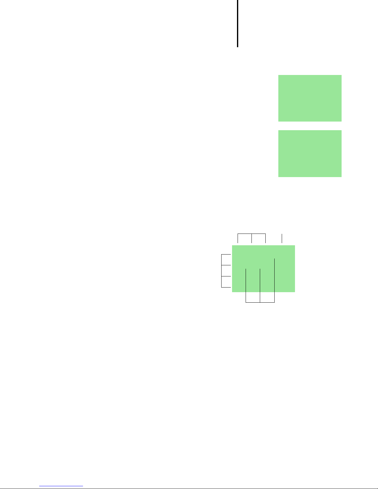
3 “easy” Interface Socket
For Immediate Delivery call KMParts.com at (866) 595-9616
The “easy” interface socket, which is hidden beneath
a protective cap, lets you plug in the optional “easy”
memory card or connect “easy” to a PC using the
optional PC interface cable and the EASY-SOFT
software. You can then copy your circuit diagrams to
and from the PC and/or memory card. In addition you
can draw and test your circuit diagrams on the PC
before transferring them to “easy”.
Memory card
Memory cards are available as the optional accessory
“easy-M-..K”. Each memory card can store a single
“easy” circuit diagram.
Information stored on the memory card is “non-volatile”
(the information is not lost when the power is switched
off), and thus you can use the card to make a backup
copy of your circuit diagram and/or to transfer it to
another “easy” device.
Each memory card stores:
the circuit diagram
all parameter settings of the circuit diagram
system settings
2
1
2
easy-M-16K
1
06/99 AWB 2528-1316 GB
43
Page 47

“easy” Interface Socket
For Immediate Delivery call KMParts.com at (866) 595-9616
Loading or storing the circuit diagram
You can only transfer the circuit diagram from “easy” to
the card or vice versa in STOP mode.
“EASY->CARD”: Transfer circuit
diagram and parameter settings
from “easy” memory to the card,
“CARD->EASY”: Transfer circuit
EASY -> CARD
CARD -> EASY
DELETE CARD
diagram and parameter settings
from the card to “easy” memory,
“DELETE CARD”: Delete the contents of the card.
Available memory cards
EASY-M-8K memory card for EASY 412-...
EASY-M-16K memory card for EASY 618/620-...
EASY-SOFT
EASY-SOFT is an optional PC program with which you
can create, store, test (simulate) and manage “easy”
circuit diagrams. You can then transfer the circuit
diagrams from the PC to “easy” or vice versa using a
special PC interface cable.
You should only transfer the circuit diagrams using the
special PC interface cable, which is available as the
optional accessory “easy-PC-CAB”.
To test your circuit diagram in the “easy” device itself,
transfer it from the PC to “easy” and choose RUN mode
by pressing the appropriate buttons.
The EASY-SOFT software also
includes extensive online Help.
To use the online Help, start
EASY-SOFT and choose
Contents in the Help menu.
Context sensitive help is also available choose a menu
item with the mouse and press F1 while keeping the
mouse button pressed.
44
06/99 AWB 2528-1316 GB
Page 48

4 Technical Data
For Immediate Delivery call KMParts.com at (866) 595-9616
Technical data
Weight 200 g, 300 g (EASY 600)
Ambient temperature,
(operation)
Protection class IP 20
Emitted interference, interference immunity
Standards and regulations
Approvals
–25 to 55 °C
EN 55011, EN 55 022, Class B
EN 50 178
UL, CSA
“easy” models
EASY 412-DC-... EASY 412-AC-... EASY 618-... EASY 620-...
...R ...RC ...TC ...TCX ...R ...RC ...RCX ...AC-RC ...DC-TC
Power supply 24 V DC power feed 115, 230, 240 V AC 100, 115, 120,
230, 240 V AC
Digital inputs 8 digital inputs, 2 of them
also usable for analog signals
8 8 8 12 12 digital
24 V DC
power feed
inputs, 2 of
them also
usable for
analog signals
Relay outputs 44–– 444 6 –
Transistor outputs––44 ––– – 8
LCD display
Operating buttons
Time switch –
Text display –––– –––
Retentive actual
values
Accessories
Software EASY-SOFT, Version 2.0, for Windows 95/98, Windows NT
PC – “easy” interface cable
Memory card EASY-M-8K EASY-M-16K
06/99 AWB 2528-1316 GB
✓✓✓
✓✓✓
✓✓✓
From version V 1.2 – – –
EASY-PC-CAB with interface electronic circuit
–
–
✓✓
✓✓
–
✓✓ ✓ ✓
–
–
✓✓
✓✓
✓✓
✓✓
45
Page 49

Tec hn i c a l D at a
47.5
56.5
58
45
4.5
For Immediate Delivery call KMParts.com at (866) 595-9616
EASY 412-DC-... EASY 412-AC-... EASY 618-... EASY 620-...
...R ...RC ...TC ...TCX ...R ...RC ...RCX ...AC-RC ...DC-TC
Input/output simu-
EASY 412-DC-SIM – – – – –
lator
Mounting feet ZB 4-101-GF1: For EASY 412-... 3 feet min. 3
Documentation Training Guide (AWB 2528-1316 GB), User Guide (AWB 2528-1304 GB), Application
Guide (TB 2528-025 GB)
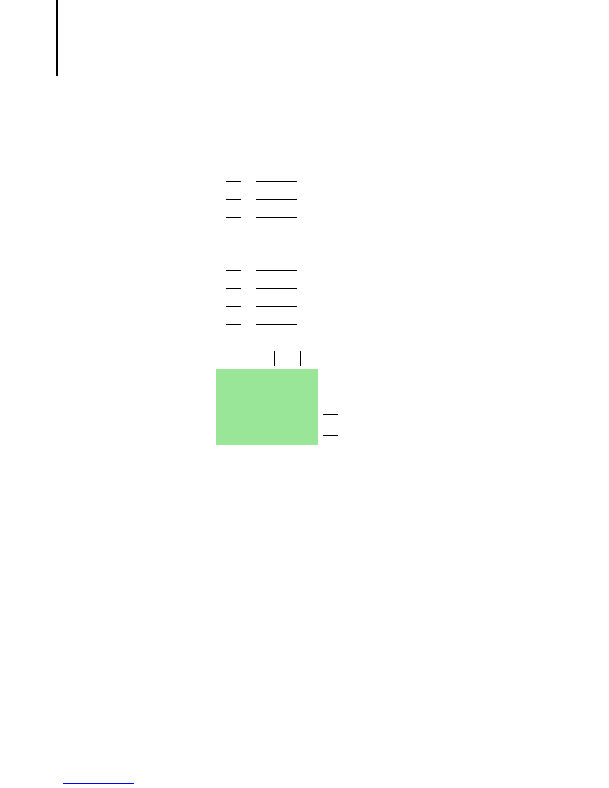
Dimensions EASY 412-...
10.75 50
90
102
110
M4
35.75
71.5
46
06/99 AWB 2528-1316 GB
Page 50

“easy” models
47.5
56.5
58
45
4.5
For Immediate Delivery call KMParts.com at (866) 595-9616
Dimensions EASY 618-..., EASY 620
75 16.2516.25
M4
107.5
90
102
110
06/99 AWB 2528-1316 GB
47
Page 51

Tec hn i c a l D at a
For Immediate Delivery call KMParts.com at (866) 595-9616
48
06/99 AWB 2528-1316 GB
Page 52

Index
For Immediate Delivery call KMParts.com at (866) 595-9616
A
Accessories .................................................................... 45
Accuracy
Analog comparator ..................................................... 35
Analog comparator ........................................................ 35
Hysteresis ................................................................... 35
AND circuit ..................................................................... 41
B
Basic circuit
Impulse relay .............................................................. 41
Parallel connection ..................................................... 42
Permanent contact ..................................................... 41
Basic circuits
Example ...................................................................... 41
Break contact ................................................................. 23
Buttons ........................................................................... 11
Use in circuit diagrams ............................................... 19
C
Change operating mode ................................................ 22
Changeover circuit ......................................................... 42
Circuit diagram
Access relay parameters ............................................ 39
Choosing relay type ................................................... 27
Displaying ................................................................... 26
Example ................................................................ 26, 37
Inserting contacts ....................................................... 26
Loading ....................................................................... 44
Select marker relay ..................................................... 37
Storing ........................................................................ 44
Symbols ...................................................................... 14
Testing ........................................................................ 28
Using a function relay ................................................. 37
Using buttons in ......................................................... 19
Circuit diagram elements ............................................... 23
Coil function ................................................................... 25
Connecting inputs ............................................................ 6
Connecting outputs ......................................................... 6
06/99 AWB 2528-1316 GB
49
Page 53

Index
For Immediate Delivery call KMParts.com at (866) 595-9616
Contactor function ......................................................... 25
Contacts
Overview ..................................................................... 23
Counter relay .................................................................. 33
Parameter display ....................................................... 33
Cursor display ................................................................ 13
D
Dimensions, “easy” ........................................................ 46
E
Overview of “easy” ........................................................... 5
Example
Basic circuits .............................................................. 41
Circuit diagram ...........................................................26
Contacts and relays .................................................... 26
Example of function relay ............................................... 37
F
Function relay
Analog comparator ..................................................... 35
Function relays
Counter relay ..............................................................33
Overview ..................................................................... 30
Time switch ................................................................. 34
Timing relay ................................................................ 30
50
H
Hysteresis
Analog comparator ..................................................... 35
I
Impulse relay .................................................................. 25
L
Language for menus
Changing .................................................................... 20
Latching circuit ............................................................... 42
Latching relay ................................................................. 25
Logic tables .............................................................. 41–42
06/99 AWB 2528-1316 GB
Page 54

Index
For Immediate Delivery call KMParts.com at (866) 595-9616
M
Make contact ................................................................. 23
Marker ............................................................................ 36
Memory card (optional) .................................................. 43
Menu guidance .............................................................. 11
Menu language
Changing .................................................................... 20
Menu structure ............................................................... 15
Models ........................................................................... 45
Mounting .......................................................................... 6
N
Negation ......................................................................... 41
NOT ................................................................................ 41
O
Operating buttons .......................................................... 11
OR circuit ....................................................................... 42
P
Parameter display
Analog comparator ..................................................... 35
Counter relay .............................................................. 33
For timing relays ......................................................... 32
Time switch ................................................................ 34
R
Relay
Impulse ....................................................................... 25
Latching ...................................................................... 25
Relay types
Overview ..................................................................... 24
Reset input ..................................................................... 25
S
Series connection .......................................................... 41
Set input ......................................................................... 25
Setting the time .............................................................. 21
Setting week days .......................................................... 21
Startup behaviour .......................................................... 22
Status display ................................................................ 12
Summer time .................................................................. 22
06/99 AWB 2528-1316 GB
51
Page 55

Index
For Immediate Delivery call KMParts.com at (866) 595-9616
Symbols in circuit diagram ............................................. 14
System menu ................................................................. 16
T
Terminals, inputs/outputs ................................................. 6
Text display .................................................................... 36
Time switch .................................................................... 34
Parameter display ....................................................... 34
Timing relays ............................................................ 30–32
Parameter display ....................................................... 32
Transfer cable ................................................................. 43
W
Winter time ..................................................................... 22
X
XOR circuit .....................................................................42
52
06/99 AWB 2528-1316 GB
 Loading...