

Page 1
01/06 AWA2528-1980
Montageanweisung
Installation Instructions
Notice d’installation
Istruzioni per il montaggio
Instrukcja montażu
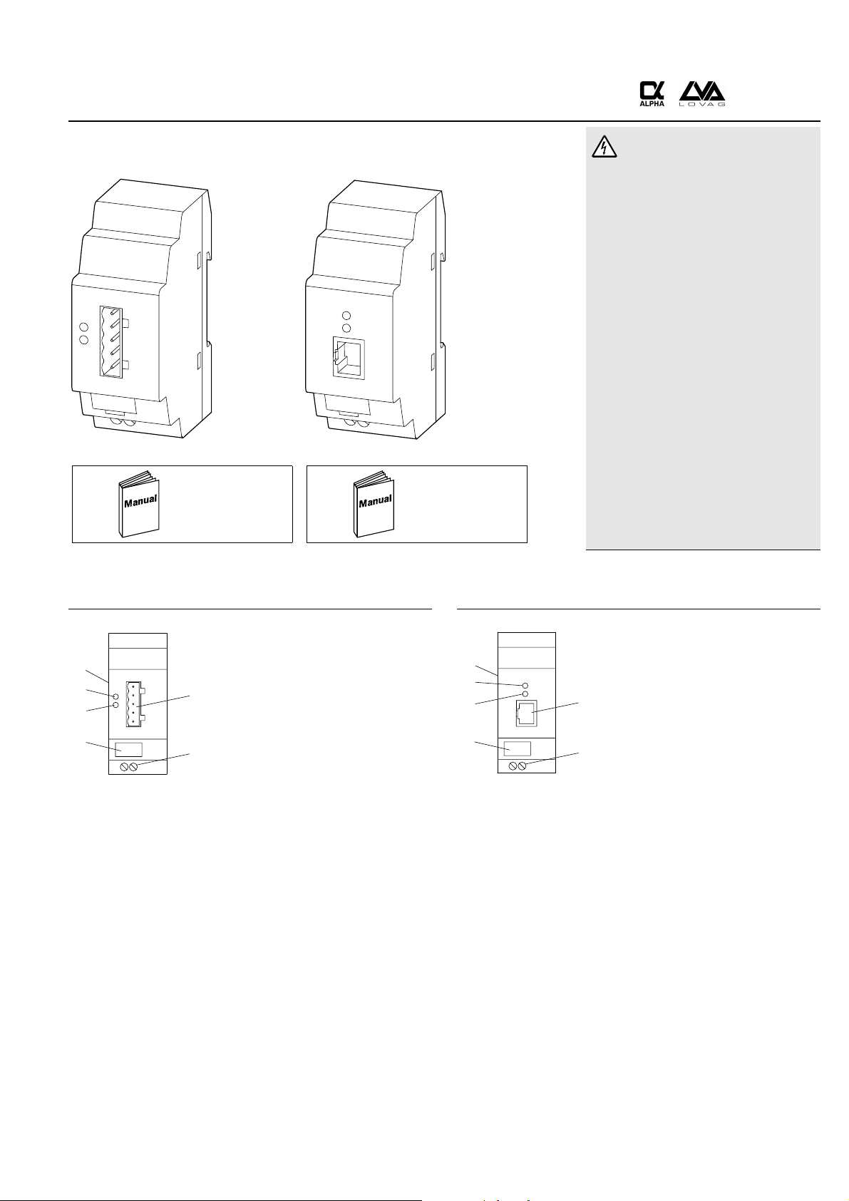
EASY222-DN EASY221-CO
MS
NS
A
AWB2528-1427...
RUN
ERR
A
AWB2528-1479...
A
Lebensgefahr durch elektrischen Strom!
Nur Elektrofachkräfte und elektrotechnisch
unterwiesene Personen dürfen die im Folgen-
den beschriebenen Arbeiten ausführen.
Die Stromversorgungsgeräte sind Einbaugeräte.
Beachten Sie für die Installation der Geräte die
länderspezifischen Vorschriften.
Electric current! Danger to life!
Only skilled or instructed persons may carry out the
following operations. The power supply units are
mounting devices. The national regulations/
specificationes must be observed for the installation
of the devices.
Tension électrique dangereuse !
Seules les personnes qualifiées et averties doivent
exécuter les travaux ci-après. Les blocs d’alimentation
sont des appareils faisant partie intégrante d’une
installation. Veuillez respecter les normes de mise en
œuvre spécifiques aux différents pays.
Tensione elettrica: Pericolo di morte!
Solo persone abilitate e qualificate possono eseguire
le operazioni di seguito riportate. Gli alimentatori
sono unità per montaggio interno. Per l’installazione
degli apparecchi è necessario rispettare le normative
specifiche di ciascun paese.
Prąd elektryczny! Zagrożenie życia!
Poniższe czynosci mogąbyć wykonywane
tylko przez przeszkolony personel.
Zasilacze mocy są elementami montażowymi.
Przy instalowaniu tych urządzeń należy
przestrzegać przepisów narodowych.
EASY222-DN a DeviceNet-Anschluss,
f
e
a
5-polige Stiftleiste
b Spannungsversorgung Gerät 24 V DC
c Gerätekennzeichnungsschild
d NS-LED (Network Status)
e MS-LED (Module Status)
f EASY-LINK-Buchse
d
a DeviceNet connection,
c
b
5-pole plug connector
b Power supply 24 V DC
c Component label
d NS-LED (network status)
e MS-LED (module status)
f EASY-LINK socket
a Connexion DeviceNet,
connecteur mâle 5 pôles
b Alimentation 24 V CC
c Etiquette d’appareil
d DEL NS (état réseau)
e DEL MS (état module)
f Prise EASY-LINK
a Collegamento DeviceNet,
connettore maschio 5 poli
b Alimentazione 24 V DC
c Targhetta apparecchio
d NS-LED (stato rete)
e MS-LED (stato modulo)
f Connettore EASY-LINK
EASY221-CO a CANopen-Anschluss,
f
e
d
a
c
b
8-polige RJ-45-Buchse
b Spannungsversorgung Gerät 24 V DC
c Gerätekennzeichnungsschild
d ERR-LED (Error)
e RUN-LED
f EASY-LINK-Buchse
a CANopen connection,
8-pole RJ 45 socket
b Power supply 24 V DC
c Component label
d ERR-LED (error)
e RUN-LED
f EASY-LINK socket
a Connexion CANopen,
RJ 45 prise 8 pôles
b Alimentation 24 V CC
c Etiquette d’appareil
d DEL ERR (erreur)
e DEL RUN
f Prise EASY-LINK
a Collegamento CANopen,
RJ 45 boccola 8 poli
b Alimentazione 24 V DC
c Targhetta apparecchio
d
ERR-LED (errore)
e RUN-LED
f Connettore EASY-LINK
aZłącze DeviceNet
5-pinowa wtyczka
bZasilanie 24V DC
cEtykieta urządzenia
dDioda LED-NS (status sieci)
eDioda LED-MS (status modułu)
fGniazdo EASY-LINK
aZłącze CANopen
8-pinowa wtyczka RJ45
bZasilanie 24 V DC
cEtykieta urządzenia
dDioda LED-ERR (błąd)
eDioda LED-Run (praca)
fGniazdo EASY-LINK
1/8
Page 2

Standardanschluss – Standard connection – Raccordement standard – Collegamento standard – Standardowe przyłączanie
+24 V
0 V
> 1 A
+24 V 0 V
Zentrale Erweiterung – Central expansion – Extension centralisée – Espansione locale – Centralne rozszerzanie
1
Einbau + , Ausbau +
Fitting + , removing +
Montage + , démontage +
Montaggio + , smontaggio +
Montaż + ,,demontaż +
2
1
2
1
1
1
2
3
4
3
4
2
2
3
4
3
4
3
4
Geräte müssen spannungsfrei sein!
Devices must be de-energized!
Assurer la mise hors tension des appareils !
Gli apparecchi non devono essere alimentati!
Urządzenia muszą być w stanie beznapięciowym!
1
2
01/06 AWA2528-1980
4
3
2/8
Page 3
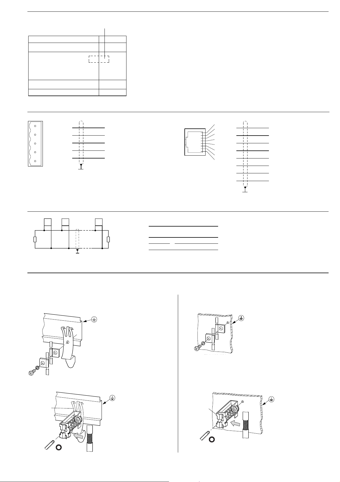
Anschluss – Connection – Raccordement – Collegamento – Przyłączanie
EASY-LINK
Basisgerät
Basic unit
Appareil de base
Apparecchio base
Jednostka podst.
EASY221-CO
EASY222-DN
DeviceNet CANopen
1
2
3
4
5
1
2
3
4
5
V–
CAN_L
Shield
CAN_H
V+ (24 V)
1
2
3
4
5
6
7
8
1
2
3
4
5
6
7
8
CAN_H
CAN_L
Ground
–
–
Shield
Ground
–
. . .
0
1
n
CANopen DeviceNet
R
T
R
T
120 O 120 O
R
T
ISO 11898 DeviceNet Specification
01/06 AWA2528-1980
Schirmerdung – Earthing the screen – Mise à la terre du blindage – Collegamento alla terra dello schermo –
Uziemienie ekranu
a für Hutschiene – for top-hat rail – pour profilé-support –
dla szyny montażowej
M4
ZB4-102-KS1
ZB4-102-KS1
bfür Montageplatte – for mounting plate – pour plaque de montage –
per piastra di montaggio – dla płyty montażowej
ZB4-102-KS1
ZB4-102-KS1
FM 4/TS 35
(Weidmüller)
KLBü 3-8 SC
(Weidmüller)
3/8
Page 4

Adressierung – Addressing – Adressage – Indirizzamento – Adresowanie
Erstinbetriebnahme – Initial commissioning – Première mise en service – Prima messa in servizio – Pierwsze uruchomienie
Geräte mit Spannung versorgen.
Entfernen Sie den CO/DN-Stecker oder brechen Sie den Datenaustausch ab und setzen Sie das Grundgerät in den STOP-Modus.
1
Apply voltage to the devices.
Remove CO/DN connector or interrupt data exchange and set the basic unit into STOP mode.
Mise sous tension des appareils.
Retirer le connecteur CO/DN ou arrêter l’échange de données et mettre l’appareil en mode d’arrêt.
Alimentare apparecchi.
Rimuovere collegamento CO/DN o interrompere scambio dati e impostare l’apparecchio di base nella modalità STOP.
Doprowadzić napięcie zasilające do urządzenia.
Usuń wtyczkę CO/DN lub przerwij wymianę danych i ustaw jednostkę podstawową w tryb "STOP".
easy600/700
2a
+
O
2b
easy800/MFD
+
PPP
CONFIGURATOR
3
GB CONFIGURATOR
D KONFIGURATOR
F PARAMETRAGE
E CONFIGURADOR
I ESPANSIONI
P CONFIGURADOR
NL CONFIGURATOR
S KONFIGURATOR
PL KONFIGURATOR
TR AYARLAR
NZM-XDMI612
2b
HAUPTMENU
MAIN MENU
MENU PRINC.
MENU PRINCIP.
MENU PRINC.
3
O
PPPPPP
P
DEVICENET
(MAX 63)
MAC-ID 0063
CANOPEN
(MAX 127)
NODE-ID 0127
CONFIGURATOR
Eingabe Passwort
Password entry
Entrée mot de passe
Immissione password
Wprowadź hasło
DeviceNet-Adresse 000 ... 63
P
DeviceNet address 000 ... 63
Adressage DeviceNet 000 ... 63
Indirizzo DeviceNet 000 ... 63
Adres DeviceNet 000 ... 63
CANopen-Adresse 001 ... 127
P
CANopen address 001 ... 127
Adressage CANopen 001 ... 127
Indirizzo CANopen 001 ... 127
Adres CANopen 001 ... 127
LINK
PPPP
EINGABEMENUE
INPUT MENU
MENU SAISIE
MENU IMMISS.
MENU ENTRADA
COM
Adresse
3
3
01/06 AWA2528-1980
Address
Adresse
Indirizzo
Dirreción
2 . . . 9 0 1 . . .
o
0 0 1 pP0 0 1
O
1 0 9 . . . 2 . . .
Adresse übernehmen – Accept address – Accepter adressage – Accettare indirizzo – Akceptacja adresu
Abbruch – Exit – Quitter le menu – Cancella – Przerwij
4/8
Page 5

EASY222-DN
Die zweifarbige LED kann GRÜN oder ROT leuchten. – The two-colour LED can show GREEN or RED. – La DEL bicolore peut présenter la couleur VERTE ou la couleur ROUGE. –
I LED di indicazione possono assumere colore verde o rosso. – Dwukolorowa dioda może swiecić kolorem zielonym lub czerwonym.
Modul Status LED (MS) – Module Status LED (MS) – DEL état module (MS) – LED stato modulo (MS) – Dioda LED-status modułu (MS)
a
t
b
t
c
t
d
t
e
t
f
t
Network Status LED (NS) – Network Status LED (NS) – DEL état réseau (NS) – LED stato rete (NS) – Dioda LED-status sieci (NS)
AUS
a
GRÜN
b
GRÜN blinkend
c
ROT blinkend
d
ROT
e
GRÜN-ROT blinkend
f
OFF
a
GREEN
b
Flashing GREEN
c
Flashing RED
d
RED
e
Flashing GREEN-RED
f
ETEINTE
a
VERTE
b
VERTE clignotante
c
ROUGE clignotante
d
ROUGE
e
VERTE/ROUGE clignotante
f
SPENTO
a
VERDE a luce fissa
b
VERDE a luce lampeggiante
c
ROSSO a luce lampeggiante
d
ROSSO a luce fissa
e
VERDE-ROSSO
f
a luce lampeggiante
OFF
a
zielona
b
zielona, błyskająca
c
czerwona, błyskająca
d
czerwona
e
zielono-czerwona, błyskająca
f
Keine Spannungsversorgung vorhanden
Das Gerät arbeitet normal.
Standby – Konfiguration falsch, unvollständig oder noch nicht erfolgt.
Störung – Kann behoben werden. Austausch nicht nötig.
Störung – Nicht zu beheben. Gerät muss ausgetauscht werden.
Selbsttest
No power supply present
Device is operating normally.
Standby – Configuration incorrect, incomplete or not yet carried out.
Error – Can be eliminated. Replacement not necessary.
Error – Cannot be eliminated. Device must be replaced.
Self test
Absence de tension d’alimentation
Fonctionnement normal de l’appareil.
Attente – Configuration incorrecte, incomplète ou non réalisée.
Défaut – Possibilité d’élimination. Remplacement inutile.
Défaut – Elimination impossible. Remplacer l’appreil.
Auto-test
Alimentazione non presente.
Funzionamento normale.
Standby – Configurazione non corretta o incompleta.
Errore – Può essere eliminato. Sostituzione non necessaria.
Errore – Non può essere eliminato. Il dispositivo va sostituito.
Il dispositivo è in auto-diagnosi.
Brak napięcia zasilającego.
Urządzenie pracuje poprawnie.
Czuwanie-niewłasciwa konfiguracja, niekompletna lub jeszcze nie zrealizowana
Błąd- może być usunięty. Wymiana nie jest konieczna.
Błąd- nie może być usunięty. Urządzenie musi być wymienione.
Autotest
01/06 AWA2528-1980
a
b
c
d
e
f
AUS
a
GRÜN blinkend
b
t
t
t
t
t
t
GRÜN
c
ROT blinkend
d
ROT
e
GRÜN-ROT blinkend
f
OFF
a
Flashing GREEN
b
GREEN
c
Flashing RED
d
RED
e
Flashing GREEN-RED
f
ETEINTE
a
VERTE clignotante
b
VERTE
c
ROUGE clignotante
d
ROUGE
e
VERTE/ROUGE clignotante
f
SPENTO
a
VERDE a luce lampeggiante
b
VERDE a luce fissa
c
ROSSO a luce lampeggiante
d
ROSSO a luce fissa
e
VERDE-ROSSO
f
a luce lampeggiante
Keine Spannungsversorgung vorhanden. Gerät nicht online.
Gerät online. Keine Verbindung hergestellt.
Gerät online. Verbindung hergestellt.
Mindestens eine I/O-Verbindung befindet sich im Time-Out-Status.
Kritischer Verbindungsfehler. Kommunikation abgebrochen.
Das Gerät hat einen Netzwerkzugangsfehler erkannt und befindet sich im
Communication-Fault-Status
No power supply present. Device not online.
Device online. No connection made.
Device online. Connection made.
At least one I/O connection is in time-out state.
Critical connection error. Communication interrupted.
The device has detected a network access error and is in communication-error status.
Absence de tension d’alimentation. Appareil non connecté.
Appareil connecté. Absence de liaison.
Appareil connecté. Liaison réalisée.
Au moins une liaison E/S se trouve en état « Timeout ».
Défaut de liaison critique. Communication interrompue.
L’appareil a détecté un défaut d’accès au réseau et se trouve en état de défaut de
communication (Communication-Fault-Status).
Alimentazione non presente. Dispositivo non in linea.
Dispositivo in linea. Connessione non stabilita.
Dispositivo in linea. Connessione stabilita.
Almeno una connessione I/O si trova in stato di time-out.
Errore critico di connessione. Comunicazione interrotta.
Il dispositivo ha rilevato un errore di accesso alla rete, e si trova in uno stato
di errore di comunicazione.
O FF
a
zielona, błyskająca
b
zielona
c
czerwona, błyskająca
d
czerwona
e
zielono-czerwona, błyskająca
f
Brak napięcia zasilającego. Urządzenie nie jest on line.
Urządzenie jest on line. Brak połączenia.
Urządzenie on line. Jest połączenie.
Przynajmniej jedno we/wy przekroczyło czas dostępu.
Krytyczny błąd połączenia. Komunikacja przerwana.
Urządzenie wykryło błąd dostępu sieciowego i jest w trybie komunikacji błędu.
5/8
Page 6

EASY221-CO
CANopen ERROR LED – Dioda LED-Error CANopen
błykająca
(czerwona)
błyskająca
(zielona)
on
off
50
ms
on
off
Nr. ERROR LED Status Beschreibung
1OffKein FehlerDas Gerät arbeitet normal.
2Einmal
aufblitzen
Alarmgrenze erreichtMindestens einer der Fehlerzähler in der CAN Steuerung
hat die Alarmgrenze erreicht oder überschritten
(zuviele Fehlertelegramme).
3FlimmerndAutoBaud/LSSAuto Baudrate Erkennung oder LSS Dienste in Gang
błyskająca
(zielona)
on
200ms200
ms
off
4Zweimal
aufblitzen
Fehlerkontrollereignis
(Error Control Event)
(flimmert abwechselnd mit RUN LED)
Ein Schutzereignis (NMT Slave oder NMT Master) oder ein
Lebenszeichenereignis (Heartbeat event) ist aufgetreten.
1)
5OnBus ausgeschaltetDie CAN Steuerung ist nicht am Bus.
on
pojedynczy
błysk
(czerwona)
200
ms
off
1000
ms
1)Ein LSS Master sollte während der Ausführung von LSS-Diensten auch seine ERROR (Fehler) und
seine RUN LED flimmern lassen.
on
pojedynczy
błysk
(zielona)
podwójny
błysk
(czerwona)
off
on
off
200
ms
200ms200ms200
1000
ms
ms
1000
ms
No ERROR LED State Description
1 Off no error The Device is in working condition.
2single flashwarning limit reachedAt least one of the error counters of the CAN controller has reached or exceeded the warning level (too many error frames).
3 Flickering AutoBaud/LSS Auto Baudrate detection in progress or LSS services in progress (alternately flickering with RUN LED)
1)
4 double flash Error Control Event A guard event (NMT-Slave or NMT-Master) or a heartbeat event has occurred.
5 On Bus off The CAN controller is bus off.
1)An LSS Master should flicker its ERROR and RUN LED as well whilst executing LSS services.
o
N
DEL ERROR Etat Description
1 Off Pas de défaut Fonctionnement normal de l’appareil.
2 Flash unique Seuil d’alarme atteint L’un au moins des compteurs de défauts de l’automate CAN a atteint ou dépassé le seuil d’alarme
(trop grand nombre de télégrammes de défaut).
3 Clignote-
ment rapide
4 Double flash Evénement de
AutoBaud/LSS Détection automatique de la vitesse de transmission ou services LSS en cours
(clignotement rapide en alternance avec la DEL RUN)
1)
Un événement de type « Guard » (esclave NMT, maître NMT) ou un événement impulsionnel (« Heartbeat ») est survenu.
surveillance de défault
(Error control event)
5 On Bus déconnecté L’automate CAN n’est pas connecté au bus.
1) Durant l’exécution de services LSS, un maître LSS devrait également laisser clignoter rapidement ses DEL ERROR (défaut) et RUN.
No ERROR LED Significato Descrizione
1 Off Nessun errore Il dispositivo funziona correttamente.
2 Flash singolo Attenzione, limite
raggiunto
3Flash
AutoBaud/LSS Autoconfigurazione del baudrate in atto o servizio LSS in atto (in lampeggio alternato con el LED di RUN)
Almeno uno dei contatori di errore del controllore CANopen ha raggiunto o superato la soglia di allarme
(troppe segnalazioni di errore).
continuo
4 Doppio flash Errore evento
Un evento Guard (NMT slave o NMT master) o un evento Heartbeat si e’verficato.
(Error Control Event)
5 On Bus off Il controllore CAN e’spento.
1) Un LSS master dovrebbe indicare il proprio errore ed azionare i LED contemporaneamente all’esecuzione del LSS services.
Nr Dioda LED-Error Stan Opis
1 Wyłączona Brak błędów Urządzenie pracuje normalnie.
2 Pojedynczy błysk Ostrzeżenie, górny limit Przynajmniej jeden z liczników błędów sieci CAN osiągnął lub przekroczył poziom ostrzegawczy
(za dużo sygnałów o błędach)
3 Błyskanie AutoBaud/LSS Trwa wkrywanie prędkosci AutoBaud lub wykonywana jest LSS (zamiennie błyskając z diodą RUN
4 Podwójny błysk Zdarzenie kontroli błędu Pojawiło się zdarzenie ostrzegawcze (NMT-Slave lub NMT-Master) lub oznaka żywotnosci
5 Swieci się Magistrala wyłączona Sterownik CAN nie jest w magistrali.
1)LSS Master powinien spowodować błyskanie diody Error i Run również podczas wykonywania usługi LSS.
01/06 AWA2528-1980
1)
1
)
6/8
Page 7

CANopen RUN LED – Dioda LED-RUN CANopen
Nr RUN LED Status Beschreibung
1 Flimmernd AutoBaud/LSS Auto Baudrate Erkennung oder LSS Dienste in Gang (flimmert abwechselnd mit ERROR LED).
1)
2 Einmal aufblitzen
Angehalten Das Gerät befindet sich im angehaltenen Status.
3 Blinkend Vorbereitungs-Status Das Gerät befindet sich im Vorbereitungsstatus.
4 On Betriebs-Status Das Gerät läuft.
1) Das einmalige Aufblitzen wurde anstatt des AUS eingeführt, um die Situation zu vermeiden, daß alle LEDs auf lange Zeit aus sind
(besonders an kleineren Geräten, die keine zusätzlichen LEDs haben, z.B. zur Anzeige der Spannungsversorgung).
No RUN LED State Description
1FlickeringAutoBaud/LSSAuto Baudrate detection in progress or LSS services in progress (alternately flickering with ERROR LED).
2single flash
1)
Stopped The Device is in STOPPED state.
3 Blinking Pre-operational The Device is in the PRE-OPERATIONAL state.
4 On Operational The Device is in the OPERATIONAL state.
1) The single flash was introduced (instead of OFF) in order to avoid situations where all LEDs are off for a long period of time
(especially on small devices that do not carry additional LEDs, e.g. for power indication).
No DEL RUN Etat Description
1 Clignotement rapide AutoBaud/LSS Détection automatique de la vitesse de transmission ou services LSS en cours
(clignotement rapide en alternance avec la DEL ERROR).
2Flash unique
1)
3 Clignotement lent Pre-operational (état
Stopped (arrêté) L’appareil se trouve à l’arrêt (STOPPED).
L’appareil se trouve à l’état pré-opérationnel (PRE-OPERATIONAL).
pré-opérationnel)
4 On Operational
L’appareil fonctionne : il est opérationnel (OPERATIONAL).
(en fonctionnement)
1) Le « flash unique » a été introduit à la place de « DEL éteinte » pour éviter que toutes les DEL restent éteintes pendant une longue période
(notamment sur les petits appareils, car ils ne sont pas équipés de DEL supplémentaires destinées par exemple à la visualisation de la tension d’alimentation).
No RUN LED Significato Descrizione
1 Flash continuo AutoBaud/LSS Autoconfigurazione del Baudrate in atto o servizio LSS in atto (in lampeggio alternato con il LED di RUN).
2 Flash singolo
1)
Fermo Il dispositivo è in stato di FERMO.
3 Lampeggio ritmico Pre-funzionamento Il dispositivo è in stato di PRE-FUNZIONAMENTO.
4 On Operativo Il dispositivo è in stato di normale FUNZIONAMENTO.
1) Il lampeggio singolo è stato introdotto (al posto di tutti i led spenti) per avere una comunicazione di stato più dettagliata.
01/06 AWA2528-1980
No Dioda LED-RUN Stan Opis
1 Błyskanie AutoBaud/LSS Trwa wykrywanie prędkosci AutoBaud lub wykonywana jest LSS (zamienne błyskając z diodą Error)
2 Pojedynczy błysk1 Zatrzymane Urządzenie jest w trybie zatrzymania
3 Błyskanie Stan przygotowania Urządzenie znajduje się w trybie przygotowania
4 Swieci się Praca Urządzenie jest w trybie pracy
1) Pojedynczy błysk został wprowadzony (zamiast Wył) aby uniknąć sytuacji, gdzie wszystkie diody są wyłączone przez dłuższy czas.
(szczególnie w małych urządzeniach, które nie posiadają dodatkowych diod LED, np. wskazania zasilania)
Abmessungen – Dimensions – Dimensioni – Wymiary [mm]
7.5
90
45
4.5
47.5
56.5
67
M4
7.5
35.5
102
110
7/8
Page 8

HAZARDOUS LOCATION – CSA (Canadian Standards Association) Certification
This equipment is suitable for use in CLASS I, DIVISION 2, GROUPS A, B, C AND D
WARNING: “EXPLOSION HAZARD – DO NOT DISCONNECT WHILE CIRCUIT IS LIVE UNLESS AREA IS KNOWN TO BE NON-HAZARDOUS“
OBSZAR NIEBEZPIECZNY- Certyfikat CSA (Canadian Standards Association)
Wyposażenie to może być stosowane w klasie I, częsć 2, grupy A,B,C i D
UWAGA : " ZAGROŻENIE WYBUCHEM - NIE ROZŁĄCZAĆ GDY OBWÓD JEST POD NAPIĘCIEM, DOPÓKI OBSZAR NIE BĘDZIE BEZPIECZNY"
01/06 AWA2528-1980
8/8
Moeller GmbH, Industrieautomation, D-53105 Bonn
© 2002 by Moeller GmbH
Änderungen
vorbehalten
01/06 AWA2528-1980 DE13 Doku/Eb
Printed in Germany (01/07)
 Loading...