

ENGNORSWE DANFINPOLRUS
RTD 61001-N1
132713.1628
Alpha IP
POL RUSFINDAN SWENORENG
2
ENG
30
3
4
DAN NOR
30
FIN
54
SWE
78
POL
102
RUS
126
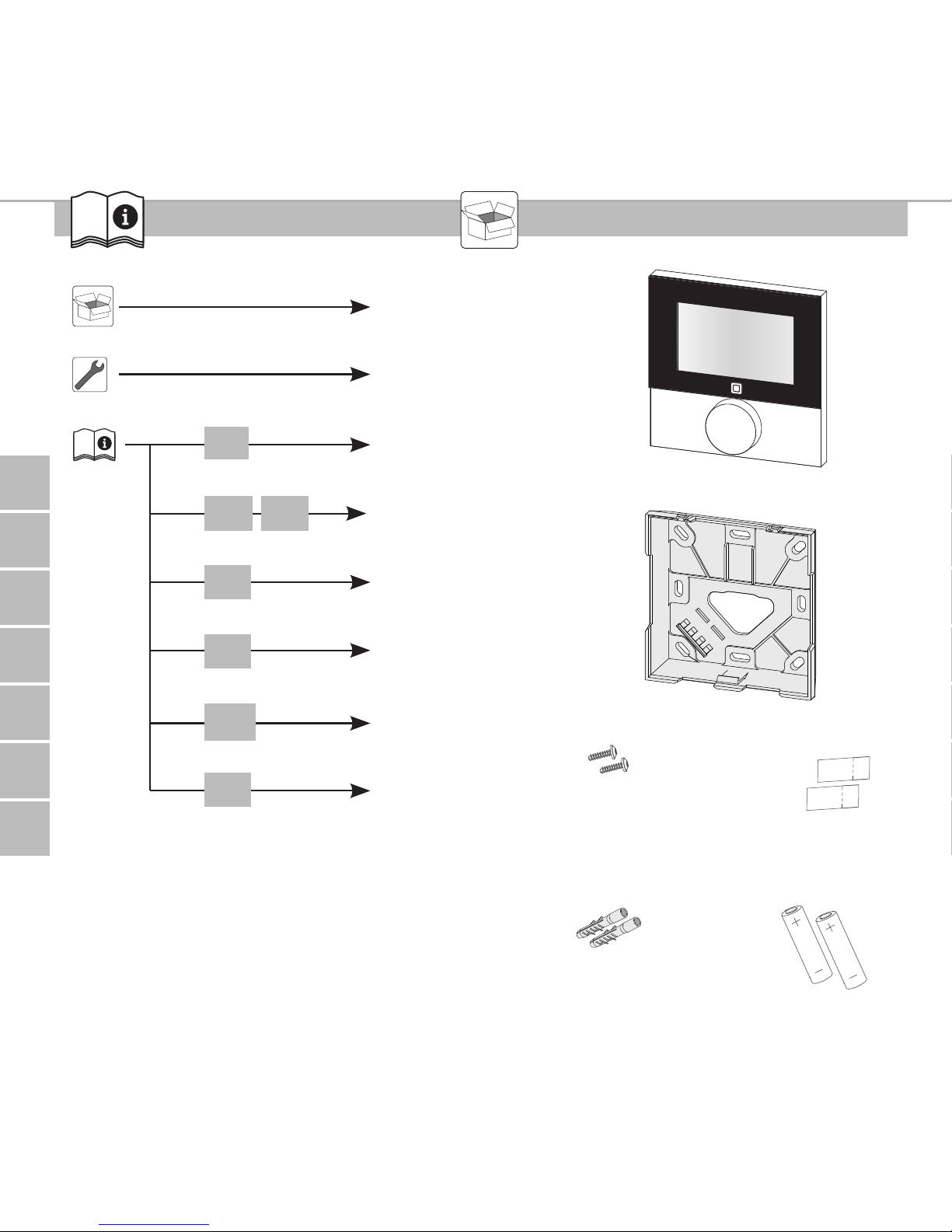
1x
1x
2x
2x
2x
2x
M3 x 30 mm
5 mm
ENGNORSWE DANFINPOLRUS
3
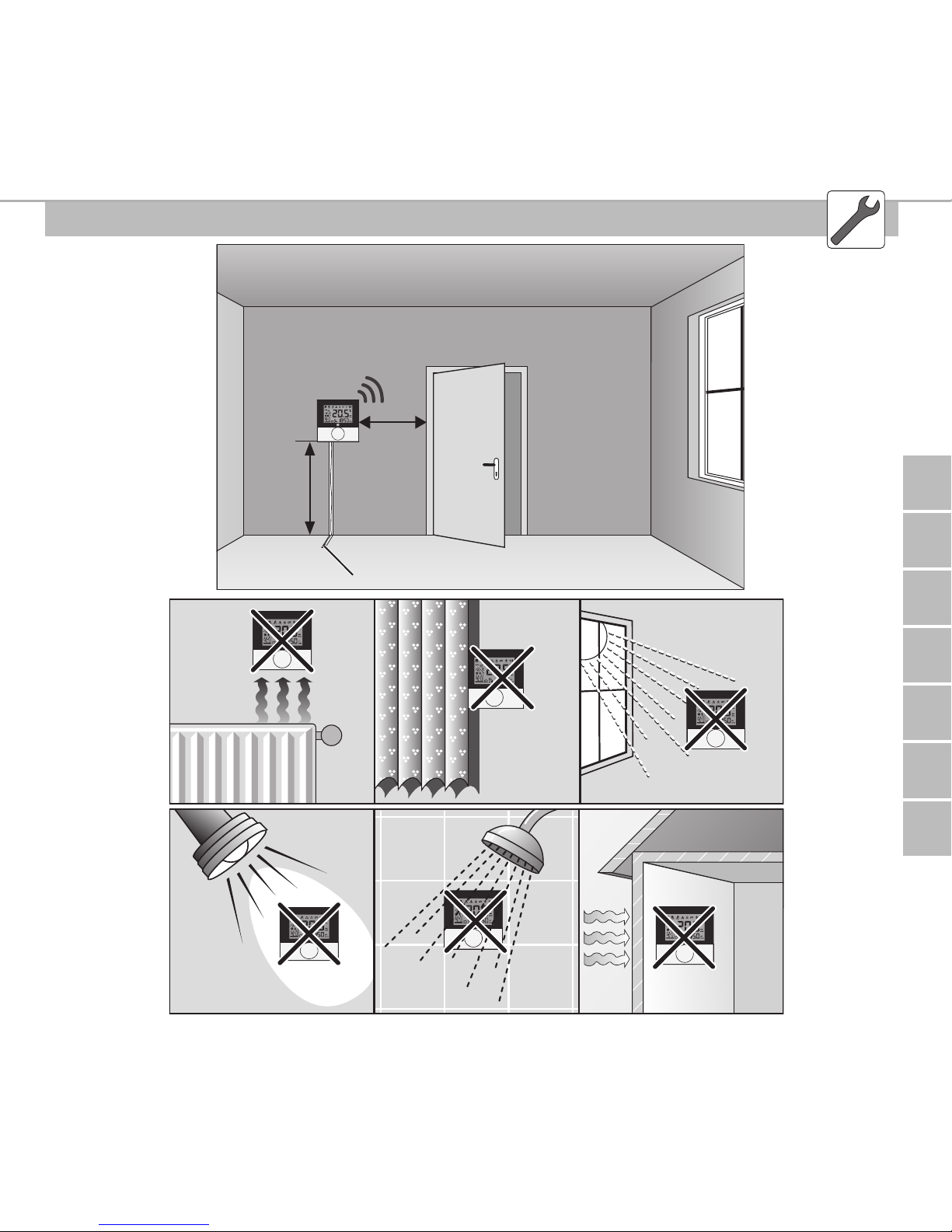
~150 cm
~ 30 cm
POL RUSFINDAN SWENORENG
4
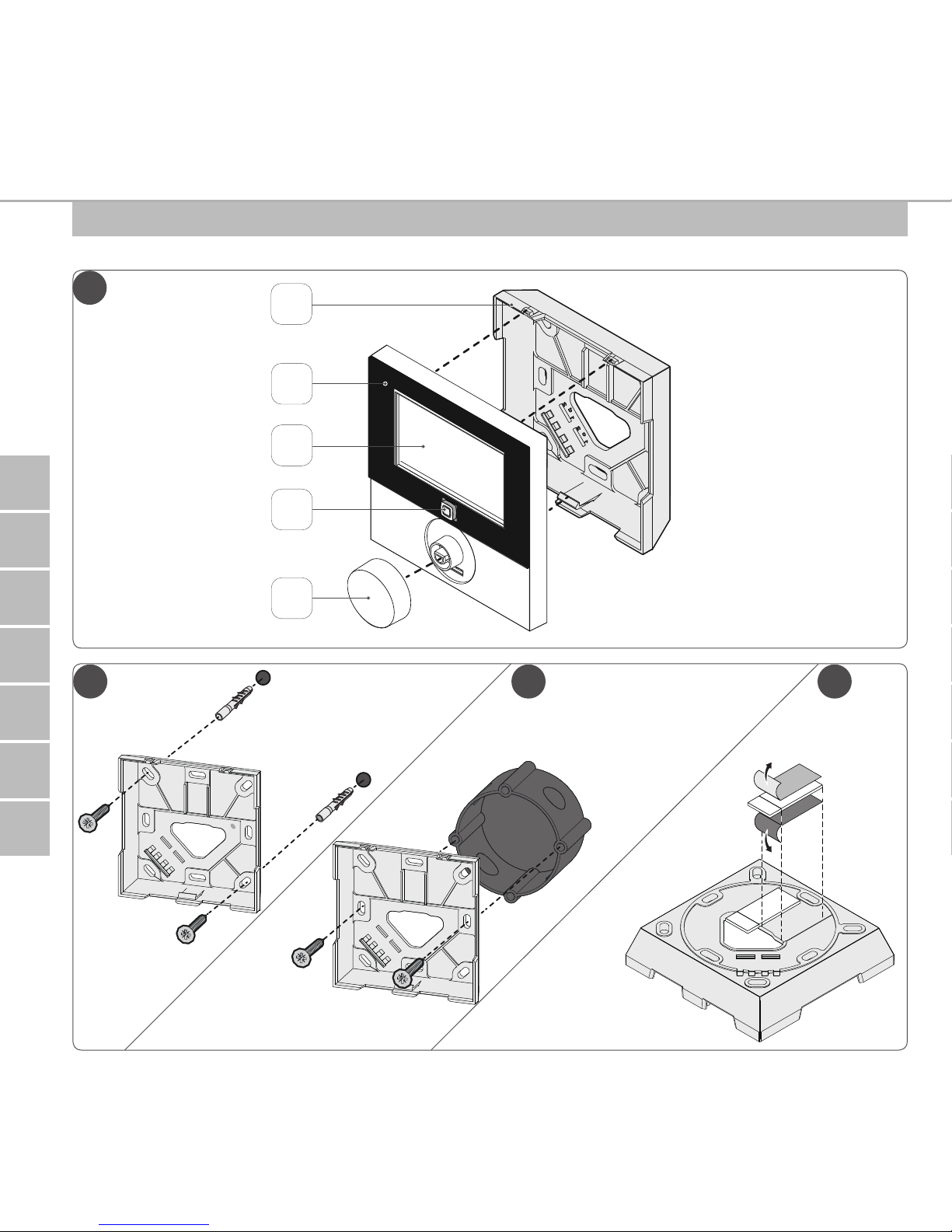
2a 2b 2c
1
B
C
D
E
A
ENGNORSWE DANFINPOLRUS
5
3
4

POL RUSFINDAN SWENORENG
6
ENG
Contents
1 About these instructions 8
1.1 Validity, storage and forwarding of the instructions 8
1.2 Symbols 8
2 Safety 9
2.1 Intended use 9
2.2 Safety notes 9
3 Function 10
4 Device overview 11
4.1 Technical data 12
5 Commissioning 13
5.1 Teaching the device 13
5.1.1 Teaching to Alpha IP Base Station 13
5.1.2 Teaching-in to Alpha IP Access Point 14
5.2 Installation 15
5.2.1 On-surface installation 15
5.2.2 Installation in flush-type box 16
5.2.3 Installation with adhesive strips 17
6 Operating modes and configuration 18
6.1 Configuration menu 18
6.1.1 Automatic mode 19
6.1.2 Manual operation 19
6.1.3 Holiday mode 19
6.1.4 Operating lock 20
6.1.5 Programming of heating profiles 20
6.1.6 Setting date and time 22

ENGNORSWE DANFINPOLRUS
7
ENG
6.1.7 Offset temperature 22
6.1.8 Selection of temperature display/humidity 22
6.1.9 Configuration of Alpha IP Base station 23
6.1.10 Connection test 23
7 Operation 24
8 Displays 25
8.1 Status indications 25
8.2 Error indications 26
9 Changing the batteries 27
10 Cleaning 27
11 Restoring the factory settings 28
12 Decommissioning 29
13 Disposal 29

POL RUSFINDAN SWENORENG
8
About these instructions
ENG
1 About these instructions
1.1 Validity, storage and forwarding of the instructions
These instructions apply to the room control unit Display RTD 61001-N1. These
instructions include information necessary for commissioning and operation. These
instructions must the read completely and thoroughly before commencing any work
with the device. These instructions must be kept and to be handed over to future
users.
The latest version of these instructions/of Additional Alpha IP System information can be found under www.alphaip.de.
System information, functions and operating steps from the instructions for
Alpha IP Access Point (HAP 21001) must be observed.
1.2 Symbols
The following symbols are used in this manual:
Note: Identifies important or useful information
Ö Preconditions
9 Result from an action
• List without fixed order
1., 2. List with fixed order

ENGNORSWE DANFINPOLRUS
9
Safety
ENG
2 Safety
2.1 Intended use
The room control unit Display RTD 61001-N1 is a component of the Alpha IP System
and serves for
• the installation in residence-related environments,
• the registration of the actual temperature (room temperature) and the humidity,
• the setting of the target temperature (comfort temperature),
• the control of the actual temperature by an activation of the Alpha IP Base station for the control of floor heating systems (FAL-x10x1-xx1) or connected Alpha
IP radiator thermostats,
• a wireless communication in the Alpha IP network.
Every other use, modification and conversion is expressively forbidden. Improper use
leads to dangers the manufacturer cannot be held liable for, and to an exclusion of
warranty and liability.
2.2 Safety notes
All safety notes in these instructions must be observed in order to avoid accidents
with personal damage or property damage. No liability is assumed for personal and
material damage caused by improper handling or non-observance of the hazard
notes. Such cases render all warranty claims invalid. No liability is assumed for consequential damage!
• Only use the device if it is in flawless state.
• Observe the performance limits of the device and its environmental conditions.

POL RUSFINDAN SWENORENG
10
Function
ENG
• Only operate this device in a dry and dust-free environment.
• Do not expose the device to humidity, vibration, continuous sunlight or other
types of heat radiation, coldness, or mechanical loads.Ensure that children do
not play with this device or the packaging. Children must be monitored if necessary.
3 Function
The Alpha IP room control unit Display RTD 61001-N1 allows to set the room temperature in a time-controlled way in order to adapt the heating phases to your individual requirements. The room control unit measures the temperature and transmits
these data cyclically to the Alpha IP Base station FAL-x10x1-xx1 or to connected
Alpha IP radiator thermostats. The registered values allow an exact regulation of
the room temperature. The target temperature can be set manually with the setting
wheel.
The range within buildings can differ strongly from the range outside (in
open air).
Communication with other components will be performed over the Homematic
(HmIP) radio protocol. The radio transmission is done on a non-exclusive transmission path; thus, disturbance cannot be completely excluded. Disturbance impacts
can be caused by switching processes, electric motors or electric appliances.

ENGNORSWE DANFINPOLRUS
11
Device overview
ENG
4 Device overview
Device overview (see page 4 fig. 1)
(A) Installation bottom
(B) Room control unit Display
(C) Display
(D) System button (teaching button
and LED)
(E) Removable setting wheel
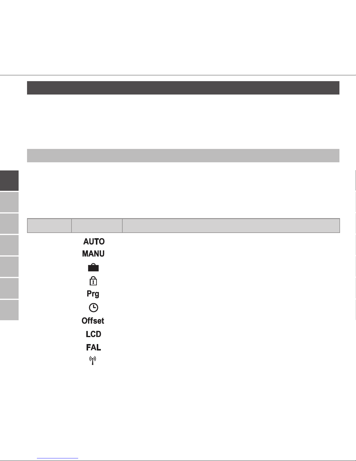
Display overview (see fig. 1)
Target/actual temperature
and humidity
Condensation warning
Window-open symbol
Battery symbol
Radio transmission
Boost mode
Manual operation
Automatic operation
Holiday mode
Heating
Cooling
Operating lock
Target temperature
Date/time
Offset
Fig. 1: Display overview

POL RUSFINDAN SWENORENG
12
Function
ENG
Short designation of
device
RTD 61001-N1
Supply voltage 2x 1.5 V LR03/micro/AAA
Power consumption max. 50 mA
Battery service life 2 years (normally)
Protection type IP20
Contamination degree 2
Ambient temperature 0 to 50 °C
Dimensions (W x H x D) 86 x 86 x 21.6 mm / 26.5 mm
Weight 110 g (including batteries)
Radio frequency 868.3 MHz/869.525 MHz
Receiver category SRD category 2
Typical radio range 250 m (in open air)
Duty Cycle < 1 % per h/< 10 % per h
Mode of action Type 1
Guidelines 2014/53/EU
2014/30/EU EMC
2011/65/EU RoHs
4.1 Technical data

ENGNORSWE DANFINPOLRUS
13
Commissioning
ENG
5 Commissioning
5.1 Teaching the device
In order be integrated into the Alpha IP System and to communicate with other
devices, the room control unit Display must be taught-in first. The room control unit
Display is taught-in directly to the Alpha IP base station, or in conjunction with the
radiator thermostats, to the Alpha IP Access Point. In case of direct teaching-in, the
configuration is done on the device itself; in case of teaching-in via the Access Point,
it is done via the Alpha IP app.
5.1.1 Teaching to Alpha IP Base Station
For teach-in, keep a minimum distance of 50 cm between the devices.
The teach-in process can be interrupted by shortly pressing the teach-in key
again. This is confirmed by a short flash in red colour of the device LED.
If no teaching-in is performed, the teach-in mode is finished automatically
after 30 seconds.
If the room control unit shall be taught-in to the Alpha IP Base station, the two
devices to be linked must be set to teach-in mode.

POL RUSFINDAN SWENORENG
14
Commissioning
ENG
1. Select the desired channel at the Alpha IP base station (see Alpha IP Base station
instructions).
2. Activate the teach-in mode at the base station by pressing and holding the key.
9 The device LED starts to flash in orange.
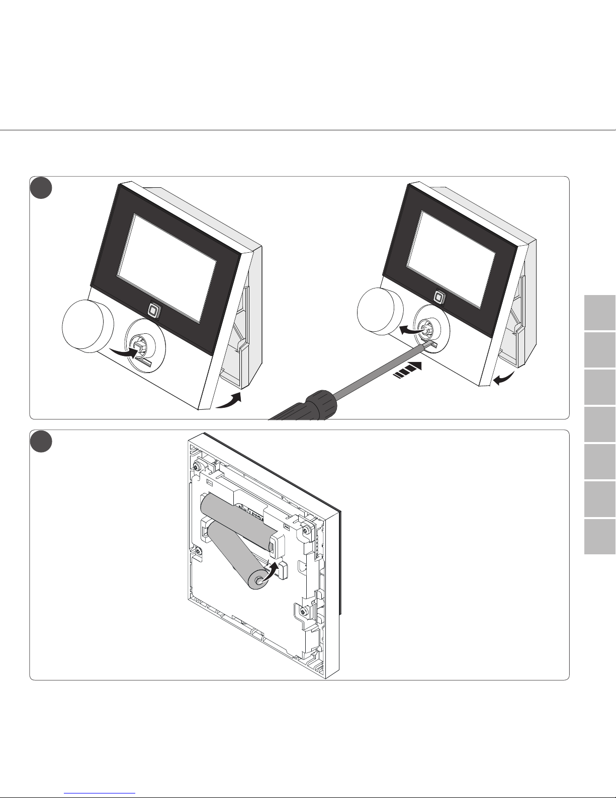
3. Take off the room control unit Display from the installation bottom (see page
5 fig. 3).
4. Pull out the insulating strip from the battery compartment, or insert batteries
(see page 5 fig. 4) If batteries have already been inserted, press the system key
(D) for at least 4 seconds in order to activate the teach-in mode.
9 The teach-in mode is activated automatically for 3 minutes.
9 The device LED flashes in orange.
The LED will light up in green after a successful teach-in process. If the LED
lights up red, repeat the process.
5.1.2 Teaching-in to Alpha IP Access Point
For a control via the Alpha IP app, the teaching-in must of the RTD 61001-N1 must
be performed via the Access Point (HAP 21001). Teach-in the device as follows:
Ö The Alpha IP Access Point has been set up via the Alpha IP App (see instructions
HAP 21001).
1. Open the Alpha IP app on the smart phone.
2. Select the menu item Teach-in device.
3. Release the room control unit Display from the installation bottom (see page 5
fig. 3).
4. Pull out the insulating strip from the battery compartment, or insert batteries (see
page 5 fig. 4) If batteries have already been inserted, press the system key (D) for at least
4 seconds in order to activate the teach-in mode.

ENGNORSWE DANFINPOLRUS
15
Commissioning
ENG
5. The device is displayed automatically in the Alpha IP app.
6. Enter the last four ciphers of the device number (SGTIN) or scan the supplied QR
code for confirmation. The device number can be found below the QR code or
in the battery compartment.
The LED will light up in green after a successful teach-in process. If the LED
lights up red, repeat the process.
7. Follow the instructions in the app.
5.2 Installation
The place of installation can be selected flexibly due to the battery operation. Installation can be performed with screws, with the supplied adhesive strips, or in a
flush-type box.
5.2.1 On-surface installation
Ö Select an appropriate installation position.
1. Ensure that the installation position is free from hidden lines.
2. If necessary, release the device from the installation bottom with a suitable
screwdriver (see page 5 fig. 3).
3. Hold the installation bottom to the installation position. Take care to align the
installation bottom correctly (see page 4 fig. 2a/b).
4. Align the installation bottom horizontally.
5. Mark two diagonally opposite bore holes using the installation bottom (see page
5 fig. 2a).

POL RUSFINDAN SWENORENG
16
Commissioning
ENG
If wood walls are present, the screws can be screwed directly into the wood.
Pre-drilling with a 1.5 mm wood drill can facilitate the installation of the
screws.
6. For stone walls, drill the holes at the marked positions with a 5 mm masonry drill.
7. Insert dowels into the bores.
8. Install the installation bottom using the supplied screws (see page 4 fig. 5).
9. Position the device onto the installation bottom and latch it in (see page 5 fig. 3).
5.2.2 Installation in flush-type box
The fixing holes on the installation bottom can be used for installation on a flushtype box (see page 4 fig. 2b).
1. If necessary, release the device from the installation bottom with a suitable
screwdriver (see page 5 fig. 4).
2. Align the installation bottom horizontally on the flush-type box.
3. Install the installation bottom with suitable screws (see page 4 fig. 2b).
4. Position the room control unit Display onto the installation bottom and latch it
into the clips (see page 5 fig. 3).

ENGNORSWE DANFINPOLRUS
17
Commissioning
ENG
5.2.3 Installation with adhesive strips
Depending on the ground, installation can be performed using the supplied double-sided adhesive tapes. Installation is possible on different grounds, as e. g. masonry, furniture, tiles or glass.
1. Select an appropriate installation position.
If the installation is done with adhesive strips, the installation surface must
be smooth, level, undamaged, clean, and free from grease and solvents.
2. Remove the protective foil from one side of the adhesive strip.
3. Fix the adhesive strip on the back side of the installation bottom in the recesses
provided for this (see page 4 fig. 2c).
4. Remove the protective foil from the other side of the adhesive strip.
5. Align the device horizontally to the desired position and press it on.
POL RUSFINDAN SWENORENG
18
Operating modes and configuration
ENG
6 Operating modes and configuration
The setting wheel E (see page 4 fig. 1) provides the operating functions of the device. Depending on the configuration, the settings are transmitted to the Alpha IP
Base station or to the Alpha IP app.
6.1 Configuration menu
The configuration menu is opened by pressing and holding the setting wheel (E).
The following symbols/menus are available by rotating the setting wheel; shortly
pressing the wheel will select them.
Section Display Meaning
6.2.1
Automatic operation
6.2.2
Manual operation
6.2.3
Holiday mode
6.2.4
Operating lock
6.2.5
Programming of heating profiles
6.2.6
Date and time
6.2.7
Offset temperature
6.2.8
Selection of temperature display/humidity
6.2.9
Configuration of the base station
6.2.10
Connection test

ENGNORSWE DANFINPOLRUS
19
Operating modes and configuration
ENG
6.1.1 Automatic mode
Do the following to activate automatic operation:
1. Press and hold the setting wheel (E) in order to open the configuration menu.
2. Select the symbol “ “ and confirm the selection by shortly pressing the
setting wheel.
6.1.2 Manual operation
Proceed as follows to activate manual operation:
1. Press and hold the setting wheel (E) in order to open the configuration menu.
2. Select the symbol “ “ and confirm the selection by shortly pressing the
setting wheel.
3. Turn the setting wheel in order to set the desired temperature.
6.1.3 Holiday mode
The holiday mode can be used if a fixed temperature shall be kept during a certain
span of time (e. g. for a vacation or during a party).
Proceed as follows to activate the holiday mode:
1. Press and hold the setting wheel (E) in order to open the configuration menu.
2. Select the symbol “ “ and confirm the selection by shortly pressing the setting
wheel.
3. Set the “Start-/End” time and date by rotating the setting wheel. Confirm each
selection by shortly pressing the setting wheel. “S” shows the starting time, “E”
shows the end time.
4. Set the temperature to be kept during the defined time by turning he setting
wheel and confirm your selection by shortly pressing the wheel.
POL RUSFINDAN SWENORENG
20
Operating modes and configuration
ENG
6.1.4 Operating lock
The operation at the device can be locked in order to prevent the unintentional
change of settings e. g. by accidental touch. Proceed as follows in order to activate
or deactivate the operation lock:
1. Press and hold the setting wheel (E) in order to open the configuration menu.
2. Select the symbol “ “ and confirm the selection by shortly pressing the setting
wheel.
3. Select “ON” by turning the wheel in order to activate the operation lock, or
“OFF” in order to deactivate the operation lock. Confirm the selection by pressing the wheel shortly.
6.1.5 Programming of heating profiles
This menu item allows to make settings for heating or cooling profiles and the creation of week profiles according to own requirements.
1. Press and hold the setting wheel (E) in order to open the configuration menu.
2. Select the symbol “ “ and confirm the selection by shortly pressing the setting
wheel.The following subordinate menu items are available in the menu, to be
accessed by turning the wheel:
“type” for switching over the base station between the modes Heating and Cooling.
1. Turn the setting wheel (E) to “HEAT” for heating or “COOL” for cooling and
confirm by shortly pressing the wheel.
“Pr.nr” for the selection of the week profile number (“no. 1, no. 2 ... no. 6”).
1. Select the number of the desired profile and confirm the selection by shortly
pressing the setting wheel.

ENGNORSWE DANFINPOLRUS
21
Operating modes and configuration
ENG
“Pr.Ad” for the individual setting of the week profiles („no. 1, no. 2 ... no. 6“). Up
to 6 heating phases (13 switch-over points) can be set in the week profile for every
week day for the selected heating profile. Programming is made for the selected
days for the time from 00:00 to 23:59 o’clock.
1. In the menu item “Pr.Ad”, select the number of the desired profile by turning
the setting wheel (E) and confirm the selection by shortly pressing the wheel.
2. Select the desired week day/working day/weekend/all days by turning the setting wheel (E) and confirm the selection by shortly pressing the wheel.
3. Confirm the start time of 00:00 o’clock by shortly pressing the setting wheel (E).
4. Select the desired temperature for the starting time by turning/pressing and confirm.
5. Select and confirm the time indicated in the display by turning/pressing the setting wheel.
6. Select the desired temperature for the set period by turning/pressing and confirm.
7. Repeat the process for the complete period from 00:00 to 23:59 o’clock.“OSSF”
serves for activating (“On”) or deactivating (“OFF”) the Smart Start/Stop function. Once this function is activated, the system calculates in a self-teaching way
when it must start the heating/cooling process in order to provide the stored
temperature exactly at the defined heating times.

POL RUSFINDAN SWENORENG
22
Operating modes and configuration
ENG
6.1.6 Setting date and time
1. Press and hold the setting wheel (E) in order to open the configuration menu.
2. Select the symbol “ “ and confirm the selection by shortly pressing the setting wheel.
3. Set the year, month, day and time by turning/pressing the setting wheel (E) and
conform each.
6.1.7 Offset temperature
Since the temperature is measured at the room control unit Display, it may be warmer or cooler in another position on the room. This deviation is corrected using the
offset temperature (up to ±3.5 °C).
1. Press and hold the setting wheel (E) in order to open the configuration menu.
2. Select the symbol “ “ and confirm the selection by shortly pressing the setting wheel.
3. Turn the setting wheel and confirm the desired offset (max. ±3.5 °C) by shortly
pressing the wheel.
6.1.8 Selection of temperature display/humidity
The display alternately shows the actual or the set temperature as well as the humidity, as required.
1. Press and hold the setting wheel (E) in order to open the configuration menu.
2. Select the symbol “ “ and confirm the selection by shortly pressing the setting wheel.
• “ACT” for displaying the actual temperature or
• “SET” for displaying the set temperature or
• “ACtH” for displaying the actual temperature and the current humidity

ENGNORSWE DANFINPOLRUS
23
Operating modes and configuration
ENG
6.1.9 Configuration of Alpha IP Base station
This menu allows to configure the Alpha IP Base station in standalone operation.
1. Press and hold the setting wheel (E) in order to open the configuration menu.
2. Select the symbol “ “ and confirm the selection by shortly pressing the setting
wheel.
If the room control unit is taught-in to more than one base stations, select
the desired base station with the setting wheel.
The device parameters “UnP1/UnP2” and the channel parameters “ChAn” are available in the configuration menu for the Alpha IP Base station; these parameters allow
the modification of the pump lead and follow-up times, setback temperatures, time
intervals and many other parameters.
Information on the configuration possibilities can be found in the Alpha IP
Base station instructions.
6.1.10 Connection test
During this verification the room control unit Display sends a switching command to
the base station. Depending on the switching status the assigned heating zone has,
it will be switched on or off after receiving the command.
1. Press and hold the setting wheel (E) in order to open the configuration menu.
2. Select the symbol “ “ and confirm the selection by shortly pressing the setting
wheel.

POL RUSFINDAN SWENORENG
24
Operation
ENG
7 Operation
The setting wheel (see position E in fig. 1) provides the operating functions of the
room control unit. The settings are transmitted to connected radiator thermostats
as well as to the Alpha IP app, and displayed there.
• Temperature: Turn the setting wheel to the right or to the left in order to
change the temperature. In automatic operation, the set temperature remains
until the next switch-over point is reached. After that, the set heating profile will
be re-activated. In manual operation, the temperature remains until the next
manual change is made.
• Manual and automatic operation: Press the setting wheel for 3 seconds in
order to change between manual and automatic operating mode. In automatic
operation, the heating profile set with the Alpha IP app is active. In manual operation, the temperature can be set at the device or using the app, and remains
until the next manual change is made.
• Boost function for the use with heating thermostats: Press the setting
wheel shortly in order to activate the boost function for quick, short-time heating. The boost function will be active for 5 minutes.
On connection the Alpha IP app, the Alpha IP Access Point offers many
configuration options, as e. g.
• Adaptation of the boost duration (up to 30 minutes)
• Activation or deactivation of the operating lock.
ENGNORSWE DANFINPOLRUS
25
Displays
ENG
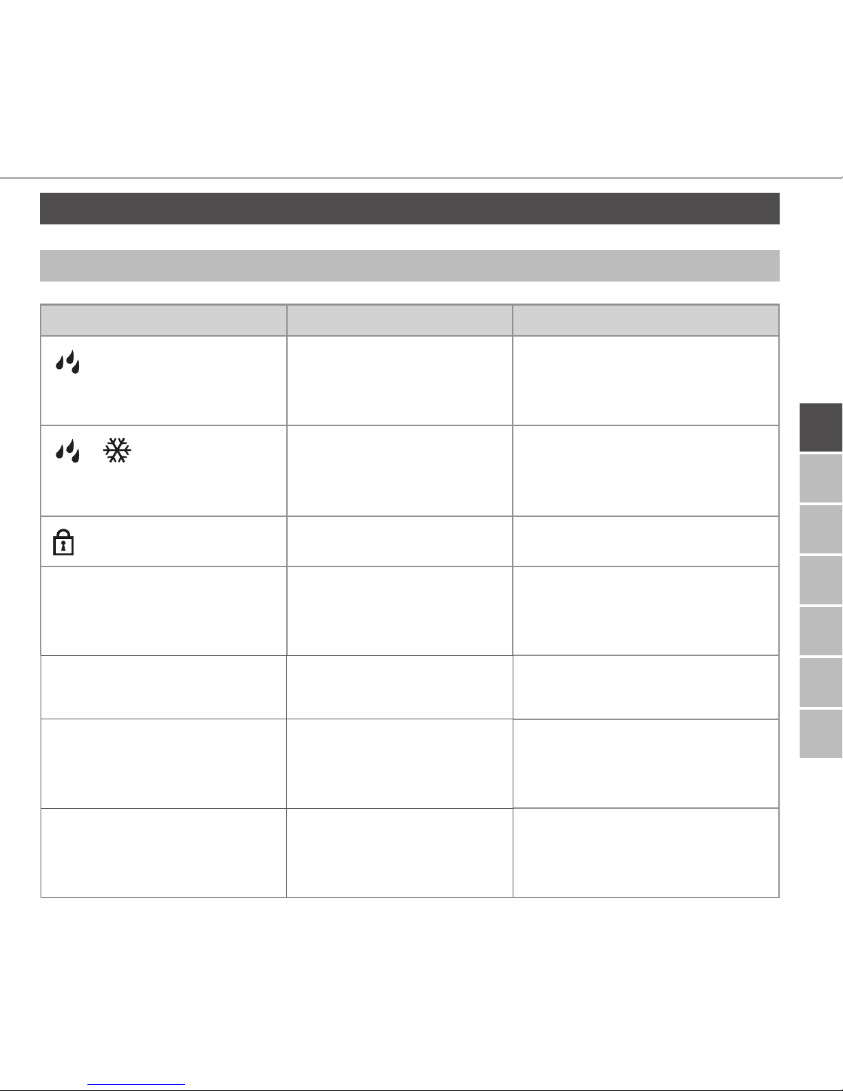
8 Displays
8.1 Status indications
Display Meaning Meaning
flashes
Humidity limit
(standard: 60 %) in
the room exceeded
Ventilate room
flash
Humidity input activated at Multi IO Box
Ventilate room
flashes
Operating lock active
Short flashing in orange Radio transmission/
Transmission attempt/
data transmission
Wait until the transmission
has finished.
1 x long illumination in
green
Process confirmed Proceed operation.
Short flashing in orange
(once every 10 sec.)
Teach-in mode active Enter the last four ciphers
of the device serial number
into the app.
1 illumination in orange
and 1 in green (after
inserting batteries)
Test indication Proceed after the LEDs
are out.

POL RUSFINDAN SWENORENG
26
Displays
ENG
8.2 Error indications
Display Meaning Solution
Battery voltage low. Change the batteries.
(flashes)
Bad connection to
the Alpha IP Access
Point
Check the connection.
Short illumination in
orange (after reception
signal)
Batteries dead Change the batteries.
Long illumination in red Transmission error,
transmission limit
reached (duty cycle)
Re-send the command, in
case of exceeding the duty
cycle after one hour at the
latest.
Check the device for a defect,
e. g. mechanical blocking.
Eliminate radio interference.
6 x long illumination
in red
Device defective Observe the indication in the
app.
Have the device checked by a
specialised dealer.
Replace the device.

ENGNORSWE DANFINPOLRUS
27
Cleaning
ENG
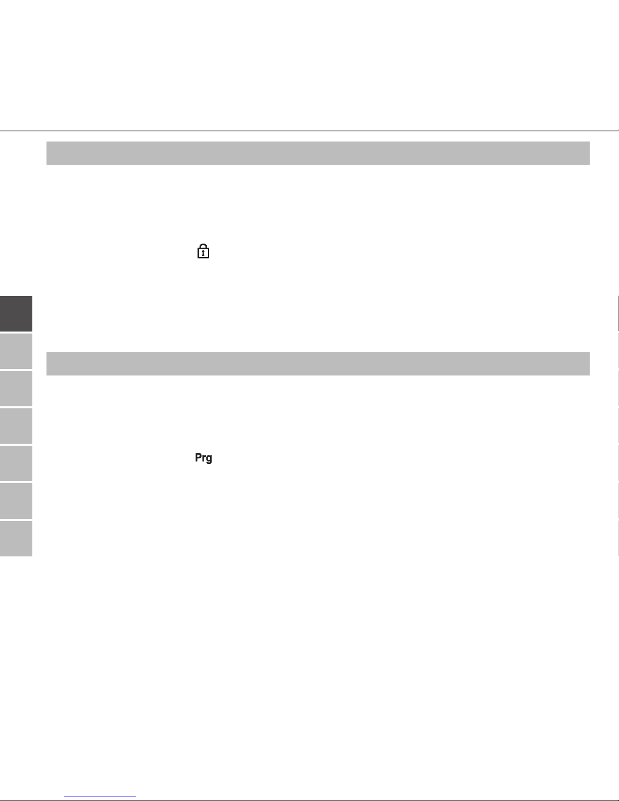
9 Changing the batteries
The symbol in the display and in the Alpha IP app indicates low battery voltage.
Replacing the batteries:
1. Take off the device from the installation bottom (see page 5, fig. 4).
2. Remove the batteries from the back side.
3. Insert two new batteries (type LR03/Micro/AAA) according to the marking.
4. Position the room control unit Display onto the installation bottom and latch
it in.
9 The display changes to normal indication.
9 The device is ready to operate.
10 Cleaning
Clean the device with a soft, clean, dry, and lint-free cloth. In order to remove heavy
contamination, moisten the cloth slightly with lukewarm water. Use a solvent-free
detergent for cleaning.

POL RUSFINDAN SWENORENG
28
Restoring the factory settings
ENG
11 Restoring the factory settings
The reset to factory setting will delete all settings made by the user.
1. Take off the device from the installation bottom (see page 5, fig. 4).
2. Remove the batteries.
3. Re-insert the batteries according to the marking in the battery compartments. At
the same time press the system key D for 4 seconds until the LED flashes rapidly
in orange.
4. Release the system button.
5. Press the system key again for 4 seconds until the LED lights up in green.
6. Release the system key.
9 The device restarts.
9 The factory settings are restored.

ENGNORSWE DANFINPOLRUS
29
Disposal
ENG
This manual is protected by copyright. All rights reserved. It may not be copied,
reproduced, abbreviated or transmitted, neither in whole nor in parts, in any form,
neither mechanically nor electronically, without the previous consent of the
manufacturer. © 2016
132713.1628
The device must not be disposed with domestic waste. The operator has the
duty to hand the device to a suitable collection point. The separate collection
and orderly disposal of all materials will help to conserve natural resources
and ensure a recycling in a manner that protects human health and the environment. If you need information about collection points for the device, please contact
your local municipality or your local waste disposal services.
1. Take off the room control unit Display from the installation bottom (see page
5 fig. 6).
2. Remove the batteries from the back side.
3. Uninstall the device and dispose of properly.
12 Decommissioning
13 Disposal

132713.1628
 Loading...