

Page 1
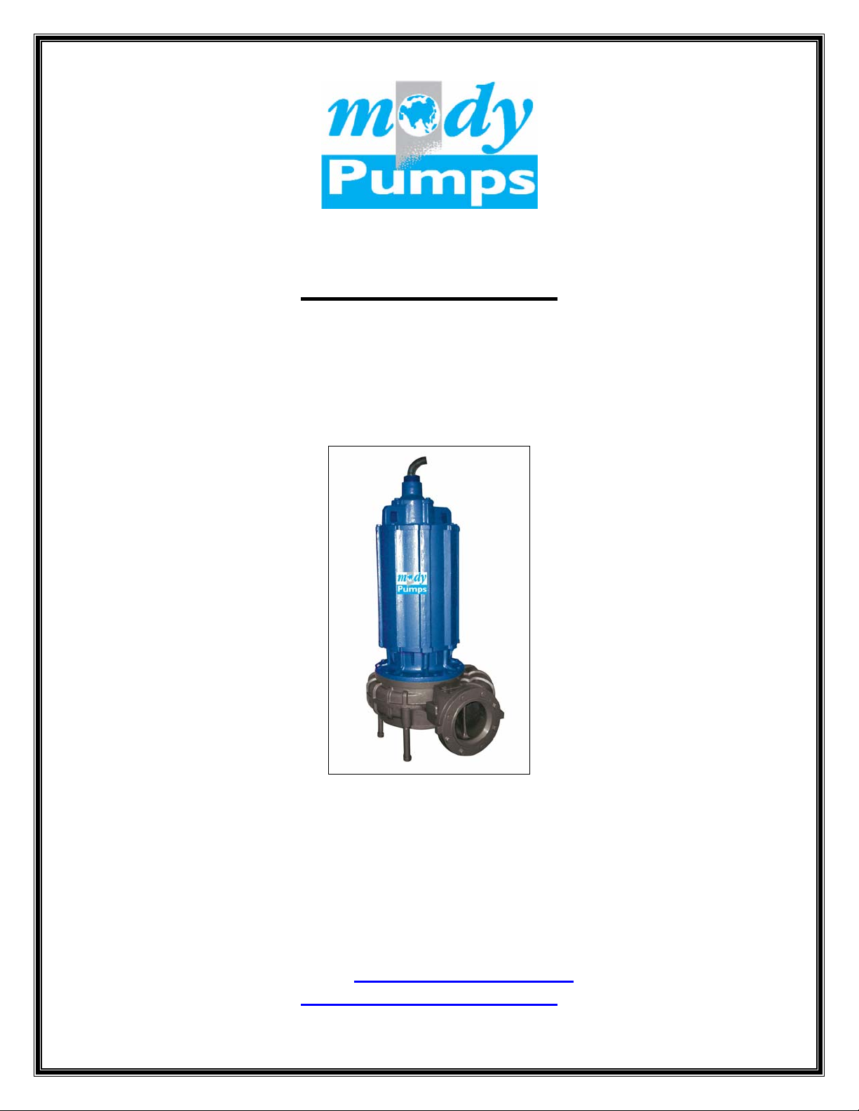
MODEL: MSXP8
OPERATING INSTRUCTIONS, INSTALLATION & MAINTENANCE
MANUAL INCLUDING SPARE PARTS LIST
Mody Pumps Inc.
2166 Zeus Court
Bakersfield, CA 93308
Tel.: (661) 392-7600 FAX.: (661) 392-7601
E-Mail: [email protected]
http://www.modypump.com
Page 2
LLIIFFEE IISS PPRREECCIIOOUUSS -- TTHHIINNKK SSAAFFEETTY
Y
1. Most accidents can be avoided by using COMMON SENSE.
2. Please read the operation and maintenance instruction manual supplied with the
pump. If you did not receive one, please call your local distributor before pump
installation.
3. Do not wear loose apparel that may become entangled in the impeller or other
moving parts.
4. Always use appropriate safety equipment, such as safety glasses, when working
on the pump or piping.
5. Pumps build up heat and pressure during operation-allow time for pumps to cool
before handling or servicing.
6. Only qualified service personnel should install, operate and repair pump.
7. Keep clear of suction and discharge openings. DO NOT insert fingers in pump
with power connected.
8. Do not pump flammable or hazardous materials (gasoline, acids, alkalis, etc.)
9. Do not block or restrict discharge hose, as it may whip or burst catastrophically
under pressure.
10. Make sure lifting handles/hooks are securely fastened each time before lifting.
11. Do not lift pump by the power cord under any circumstances.
12. Do not exceed manufacturer's recommendation for optimum performance, as this
could cause the motor/pump to overheat and lead to premature wear or failure.
13. Secure the pump in its operating position so it does not tip over, fall or slide.
14. Keep away from impeller when power is connected.
15. Submersible Pumps are not approved for use in swimming pools, recreational
water installations, decorative fountains or any installation where human contact
with the pumped fluid is common.
16. Do not operate pump without adequate protection and safety devices in place.
17. Always replace safety devices that have been removed during service or repair.
18. To reduce risk of electrical shock, pump must be properly grounded in
accordance with the National Electric Code and all applicable state and local
codes and ordinances.
19. To reduce risk of electrical shock, always disconnect the pump from the power
source before handling or servicing.
20. Any wiring of pumps should be performed by a qualified electrician.
21. Never operate a pump with a power cord that has frayed or brittle insulation.
22. Cable should be protected at all times to avoid punctures, cuts, and
abrasions - inspect frequently.
23. Never handle connected - "hot" power cords with wet hands.
24. Never operate a pump with a plug-in type power cord without a ground fault
circuit interrupter, adequate overload and short circuit protection.
IMPORTANT !!! Mody Pumps Inc. is not responsible for losses, injury, or death resulting
from a failure to observe these safety precautions, misuse or abuse of pumps or
equipment.
Mody Pumps Inc.: 2166 Zeus Court, Bakersfield, CA 93308 Tel.: (661) 392-7600 Fax: (661) 392-7601
Page 3

GENERAL INFORMATION.
“MSXP” SERIES OF MODY'S SUBMERSIBLE SEWAGE PUMPS ARE PRIMARILY DESIGNED FOR
THE
HANDLING SEWAGE, SLUDGE, WASTEWATER AND LIQUID MANURE IN CLASS 1 DIVISION 1
GROUP C & D ENVIRONMENTS. THEY CAN ALSO BE USED FOR HANDLING STORMWATER
DRAINAGE WITH HIGH SOLIDS CONTENT.
THE SERVICE LIFE OF A SUBMERSIBLE PUMP PRIMARILY HINGES ON TWO ASPECTS: THE
DEPENDABILITY OF THE SEALING SYSTEM AND THE WEAR RESISTANCE OF THE PUMP ITSELF.
THE “MSXP” SERIES OF PUMPS ARE AVAILABLE WITH A WIDE RANGE OF IMPELLERS TO SUIT
PRACTICALLY EVERY PUMPING DUTY WITH HIGH EFFICIENCES AND DIFFERENT IMPELLER
TRIMS.
THE MSXP6 HAS A SINGLE CHANNEL IMPELLER WITH PUMP OUT VANES ON THE BACK SIDE
AND 75MM/3” SOLIDS HANDLING CAPABILITY WITH A BRONZE WEAR RING. THE MSXP6PE HAS
A 3 VANE CHANNEL IMPELLER WITH PUMP OUT VANES ON THE BACK SIDE AND 75MM/3”
SOLIDS HANDLING CAPABILITY WITH A BRONZE WEAR RING.
IMPELLERS ARE IN CAST IRON CONSTRUCTION. THE PUMP VOLUTES ARE ALSO IN CAST IRON
WITH SMOOTH PROFILED GEOMETRY FOR CLOG FREE OPERATION AND HIGH EFFICIENCES. ALL
VOLUTES ARE FITTED WITH REPLACEABLE WEAR RINGS.
IT IS IN THE INTEREST OF THE USER THAT HE/SHE GO THROUGH THIS MANUAL IN DETAIL
PRIOR TO USING THE PUMP.
TECHNICAL DESCRIPTION.
THE PUMPSET IS IN A MODULAR CONSTRUCTION ENSURING EASY AND SIMPLE
SERVICEABILITY. THE MAJOR DESIGN FEATURES ARE AS UNDER:
A] THERMAL PROTECTION : SEE UNDER "MOTOR PROTECTION" .
B] THE MOTOR: UL APPROVED EXPLOSION PROOF CLASS 1, DIV. 1, GROUP C & D THREE
PHASE AIR FILLED 6 & 8 POLE CONTINUOUS DUTY RATED (15 MIN. IN AIR) SQUIRREL
CAGE MOTOR WITH DIE CAST ALUMINUM ROTOR. BI-METALLIC SWITCHES EMBEDDED IN
STATOR WINDING TO PROTECT AGAINST OVERHEATING. STATOR INSULATION CLASS “F”.
C] THE SEAL CHAMBER: THE HEART OF THE "MODY" PUMP. DUAL MECHANICAL SEALS,
STANDARD UPPER SEAL IS CARBON/CERAMIC (OPTIONAL SILICON CARBIDE/SILICON
CARBIDE), LOWER SEAL IS SILICON CARBIDE/SILICON CARBIDE. SECONDARY SEALS OF
NITRILE RUBBER AND METAL PARTS IN STAINLESS STEEL, RUNNING IN AN OIL BATH.
D] BEARINGS: DOUBLE ROW ANGULAR CONTACT LOWER BEARING, WITH SINGLE ROW DEEP
GROOVE UPPER BALL BEARING GREASED FOR LIFE WITH A SPECIAL HIGH TEMPERATURE
BEARING GREASE REQUIRING NO PERIODIC MAINTENANCE WHATSOEVER.
E] THE HYDRAULIC ELEMENTS: SINGLE CHANNEL AND THREE VANE IMPELLERS WITH LARGE
SOLIDS HANDLING CAPACITY. SMOOTH PROFILED VOLUTES FOR HIGH EFFICIENCES.
F] CABLE GLAND ASSEMBLY: THE PUMP IS SUPPLIED WITH 25’ POWER CABLE AS
STANDARD. THE CABLE IS SIZED ACCORDING TO MOTOR HP. 25’ TRAILING CABLE
INCORPORATING THERMAL OVERLOADS AND SEAL PROBE SENSOR ARE STANDARD. THE CABLE
IS TERMINATED IN THE PUMP AT THE CABLE GLAND. THE GLAND ASSEMBLY SEALS THE
CABLE ON THE OUTSIDE SHEATH AND THE ENTIRE ASEMBLY IS EPOXY SEALED.
G] ELECTRICAL INFORMATION: MOTORS ARE DESIGNED TO OPERATE ON SINGLE VOLTAGE
AND FREQUENCY. MAXIMUM DEVIATION IN VOLTAGE ALLOWED IS -/+ 6% AND FREQUENCY -/+
3%. CHECK NAME PLATE FOR OPERATING VOLTAGE AND FREQUENCY. 230/460V DUAL WIRED
MOTORS STANDARD IN NORTH AMERICA.
Page 4
DESIGN PARAMETERS :
• LOWEST LIQUID LEVEL SHOULD BE 0.3 MTRS (12”) ABOVE PUMP BASE.
• THE MAXIMUM SUBMERGENCE RECCOMENDED IS 15 METRES. (50’)
• THE SPECIFIC GRAVITY OF THE PUMPED FLUID SHOULD NOT EXCEED 1.1.
• MAXIMUM FLUID TEMPERATURE IS 40 DEG. CELSUIS.
• pH OF THE PUMPED FLUID : 6 - 11
INSTALLATION
PUMPS ARE AVAIABLE FOR TWO TYPES OF INSTALLATION:
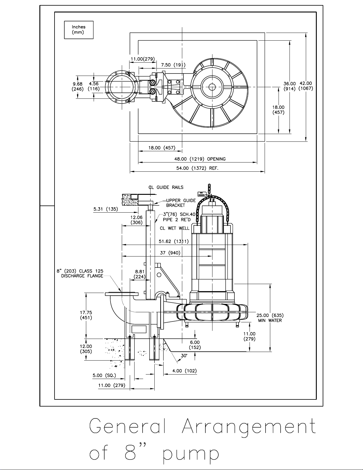
P TYPE INSTALLATION: SEMI PERMANENT/WET. PUMPS ARE LOWERED DOWN GUIDE BARS TO
AUTOMATICALLY CONNECT TO DISCHARGE PIPING. PLEASE SEE ILLUSTRATION AT END OF
MANUAL FOR DETAIL DIMENSIONS AND INSTALLATION.
S TYPE INSTALLATION: PORTABLE/WET. VERSATILE, MULTIPURPOSE, EASY TO INSTALL AND
MOVE FROM SUMP TO SUMP. PUMP IS AVAILABLE WITH HOSE/FLANGE TYPE OUTLET
CONNECTION AND INDEPENDENT BASE STAND. SEE ILLUSTRATION AT END OF MANUAL.
• CHECK THAT THE SITE VOLTAGE CORRESPONDS WITH THAT OF THE PUMP.
• CHECK THAT FUSES ARE INTACT.
• USE SHORTEST POSSIBLE HOSE OF RECOMMENDED DIMENSION. AVOID SHARP BENDS,
CREASES AND CONTRACTIONS. FOR P TYPE AND D TYPE INSTALLATIONS ENSURE ALL
ACCESSORIES ARE AVAILABLE BEFORE STARTING INSTALLATION.
• NEVER LIFT OR PULL THE PUMP BY MEANS OF THE CABLE. SUSPEND THE PUMP BY A
ROPE/CHAIN OR PREFERABLY PLACE IT ON A SOLID BASE. FOR P TYPE INSTALLATIONS
THE REQUISITE CHAIN & TACKLE EQUIPMENT MUST BE AVAILABLE. PLEASE READ OUR
PUBLICATION REGARDING “P” TYPE INSTALLATION.
• WIRE THE PUMP TO THE MAINS CORRECTLY. ALWAYS USE A STARTER OR A PANEL BOARD.
SEE INSTRUCTIONS UNDER "MOTOR PROTECTION" BELOW.
• WHEN THE PUMP IS ENERGIZED IT WILL KICK, WHICH IS OPPOSITE TO THE DIRECTION
OF ROTATION OF THE IMPELLER. SHIFT TWO PHASES IN THE POWER CONNECTION IF THE
KICK IS IN THE WRONG DIRECTION. THE CORRECT DIRECTION IS INDICATED ON THE
PUMP COVER AT THE TOP OF THE PUMP.
• CHECK LEVEL AND CONDITION OF THE OIL AT SERVICE EVERY SIX MONTHS. IF THE OIL
IS EMULSIFIED BY WATER THE SEALS MUST BE REMOVED FROM THE ROTOR SHAFT FOR
FURTHER ACTION. THE SHAFT SEAL SHOULD BE CHECKED FOR WEAR EVERY 2500 HRS. OF
OPERATION. IF SEAL FACES SHOW ANY SIGNS OF WEAR, THEY SHOULD BE REPLACED.
.
Page 5
TROUBLE GUIDE CAUSE REMEDY
1.FUSES BLOWN. 1.REPLACE FUSES
2.CABLE DAMAGED 2.SHORTEN/REPLACE CABLE
PUMP DOES NOT START 3.NO POWER. 3.CHECK POWER SUPPLY
4.BLOCKED IMPELLER. 4.CLEAN BOTTOM PARTS.
5.STATOR WINDING BURNT. 5.REPLACE STATOR.
1.BLOCKED IMPELLER. 1.CLEAN BOTTOM PARTS.
2.IMPELLER ROT.WRONG 2.SHIFT TWO PHASE CONN.
PUMP STARTS BUT STOPS. 3.CONNECTED FOR WRONG 3.CHECK & RECONNECT.
VOLTAGE.
4.VOLTAGE TOO LOW/HIGH. 4.APPROACH POWER CO.
5.LIQUID DENSITY HIGH 5.HIGHER HP REQUIRED.
6.BI-METAL TRIPS. 6.CHECK CURRENT.
1.IMPELLER ROT.BACKWARD. 1.SHIFT TWO PHASE CONN.
2.PUMP WORN DOWN. 2.REPLACE IMPELLER.
PUMP GIVES TOO LITTLE 3.LONG HOSE AND DIAMETER 3.CHECK PRESSURE LOSSES
WATER. TOO SMALL.
4.PRESSURE HEAD TOO HIGH 4.INSTALL BIGGER PUMP.
5.WEARING RING WORN OUT. 5.REPLACE WEAR RING.
Page 6
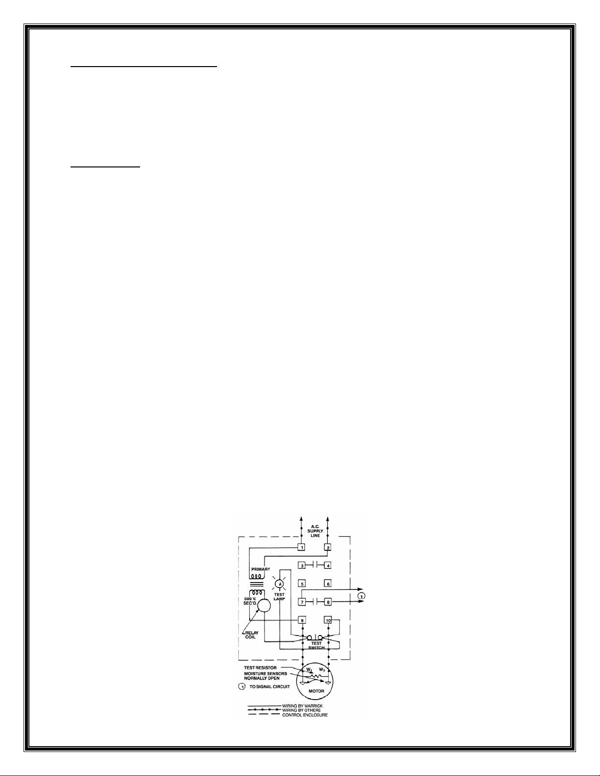
MOTOR PROTECTION
IT IS ESSENTIAL THAT THE PUMP BE USED WITH A STARTER AND PREFERABLY A PANEL
BOARD. CONTROL PANELS INCORPORATING ALL PROTECTIVE DEVICES ARE READILY
AVAILABLE. PLEASE CONTACT YOUR NEAREST DISTRIBUTOR. THE OVERLOAD RELAY IN THE
STARTER SHOULD BE CHOSEN ACCORDINGLY AND AMPERES SET AT THE FULL LOAD SETTING
FOR THE PARTICULAR MODEL OF THE PUMP.
IMPORTANT.
THE PUMP IS SUPPLIED WITH TWO CABLES:
• RED/WHITE/BLACK ARE THE POWER CORES.
• GREEN CORE IS FOR EARTHING.
• TRAILING CABLE - BLACK (P1) & WHITE (P2) ARE THERMALS AND RED (W1) & ORANGE
(W2) ARE MOISTURE LEADS
PLEASE SEE ENCLOSED WIRING INFORMATION ON MOTOR AND THERMAL/MOISTURE
PROTECTION.
THE SUBMERSIBLE MOISTURE PROTECTION SYSTEM CONSISTS ON THE NON-WICKING CABLE
CAP ASSEMBLY AND THE DUAL MOISTURE SENSING PROBES. THE CABLE CAP ASSEMBLY
PREVENTS MOISTURE FROM WICKING THROUGH THE CABLE ASSEMBLY EVEN WHEN THE CABLE
JACKET HAS BEEN PUNCTURED. POWER AND CONTROL CONDUCTORS ARE STRIPPED BARE AND
TERMINATED IN BUTT CONNECTORS. THE CABLE AND BUTT CONNECTOR ASSEMBLIES ARE
ENCAPSULATED IN EPOXY ASSURING A POSITIVE BOND TO THE CONDUCTORS. CONCENTRIC
RINGS IN THE CAP ASSEMBLY ASSURE THAT A POSITIVE BOND EXITS BETWEEN THE EPOXY
AND THE MOTOR HOUSING.
DUAL MOISTURE SENSING PROBES (WARWICK TYPE) EXTEND INTO THE OIL CHAMBER LOCATED
BETWEEN THE TANDEM MECHANICAL SEALS. SHOULD THE OUTER SEAL FAIL, WATER WILL
ENTER THE OIL CHAMBER THROUGH THE LABYRINTH SLINGER PATHS AND CREATE A
WATER/OIL EMULSION IN THE OIL CHAMBER. THE MOISTURE DETECTION CONTROL SYSTEM
APPLIES 500 VOLTS TO THE MOISTURE PROBES. THE PRESENCE OF WATER IN THE OIL
CHAMBER INCREASES THE CONDUCTIVITY SUFfiCIENTLY TO INCREASE CURRENT flOW THROUGH
THE PROBE CIRCUIT WHICH ILLUMINATES A WARNING LIGHT AND ACTIVATES A RELAY TO
DE-ENERGIZE THE MOTOR. THE RELAY IS PURCHASED SEPARATELY. THE MOISTURE
DETECTION CONTROL SYSTEM MUST BE SO CONNECTED FOR THE WARRANTY AND THE U/L
LISTING TO BE VALID.
Page 7
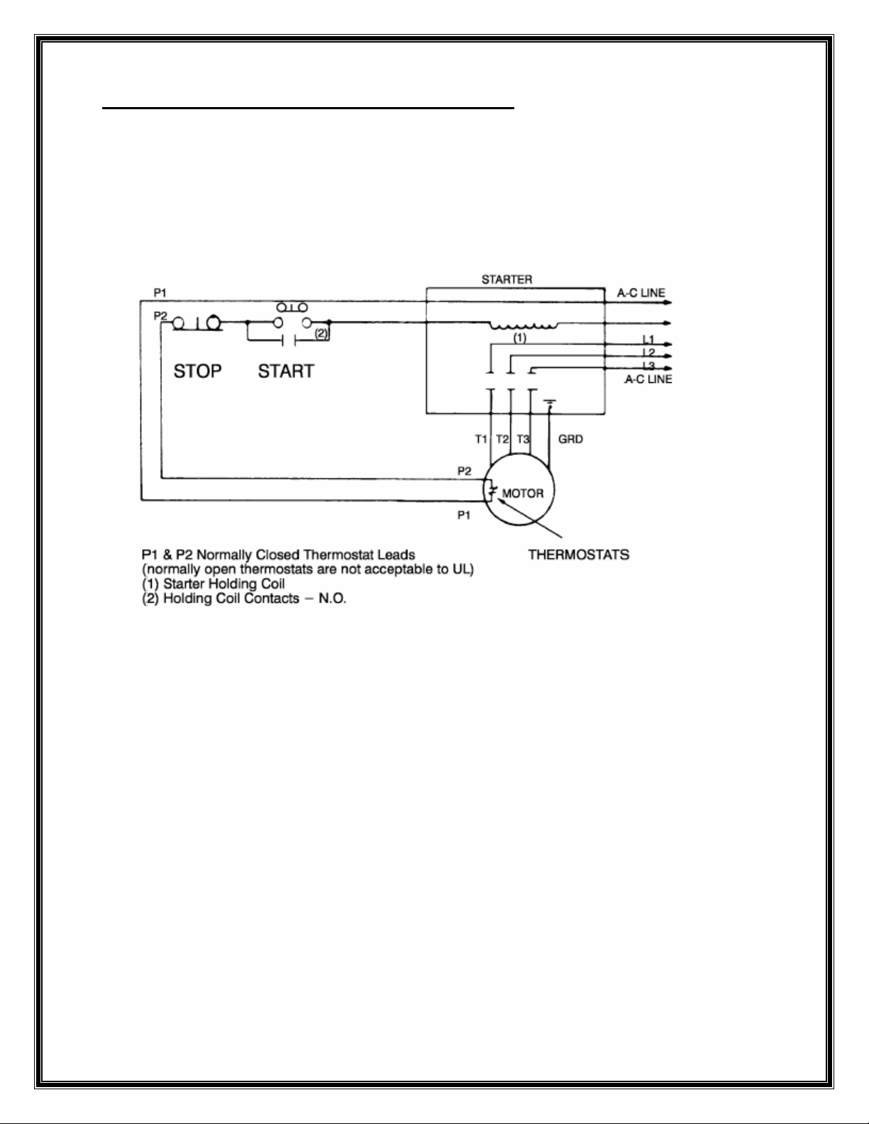
TYPICAL THERMAL PROTECTION WIRING CIRCUIT:
THERMALS NORMALLY CLOSED ARE WIRED IN SERIES WITH THE COIL ON THE
CONTACTOR/MAGENETIC STARTER. WHEN THE MOTORS BEGINS TO OVERHEAT THE THERMAL
SWITCHES OPEN AND CURRENT STOPS FLOWING THROUGH THE COIL EFFECTIVELY TRIPPING
THE CONTACTOR. NOTE THAT THE THERMALS DO NOT PROVIDE ANY LOCKED ROTOR
PROTECTION. WE RECOMMEND USING A MOTOR CIRCUIT PROTECTOR THAT PROVIDES SHORT
CIRCUIT AND OVERLOAD PROTECTION.
Page 8

GENERAL OVERHAUL AND OIL CHECK.
MOTORS ARE UL LISTED FOR APPLICATIONS IN CLASS 1, DIV 1, GROUPS C
& D EXPLOSION PROOF ENVIRONMENTS. ALL REPAIRS OTHER THAN LEAD
RECONNECTS AND OUTER SEAL REPLACEMENT SHALL BE PERFORMED BY AN
AUTHORIZED RELIANCE SERVICE FACILITY. ANY OTHER REPAIRS PERFORMED
BY THE END USER OR CUSTOMER NEGATES THE UL LISTING AND MOTOR
WARRANTY.
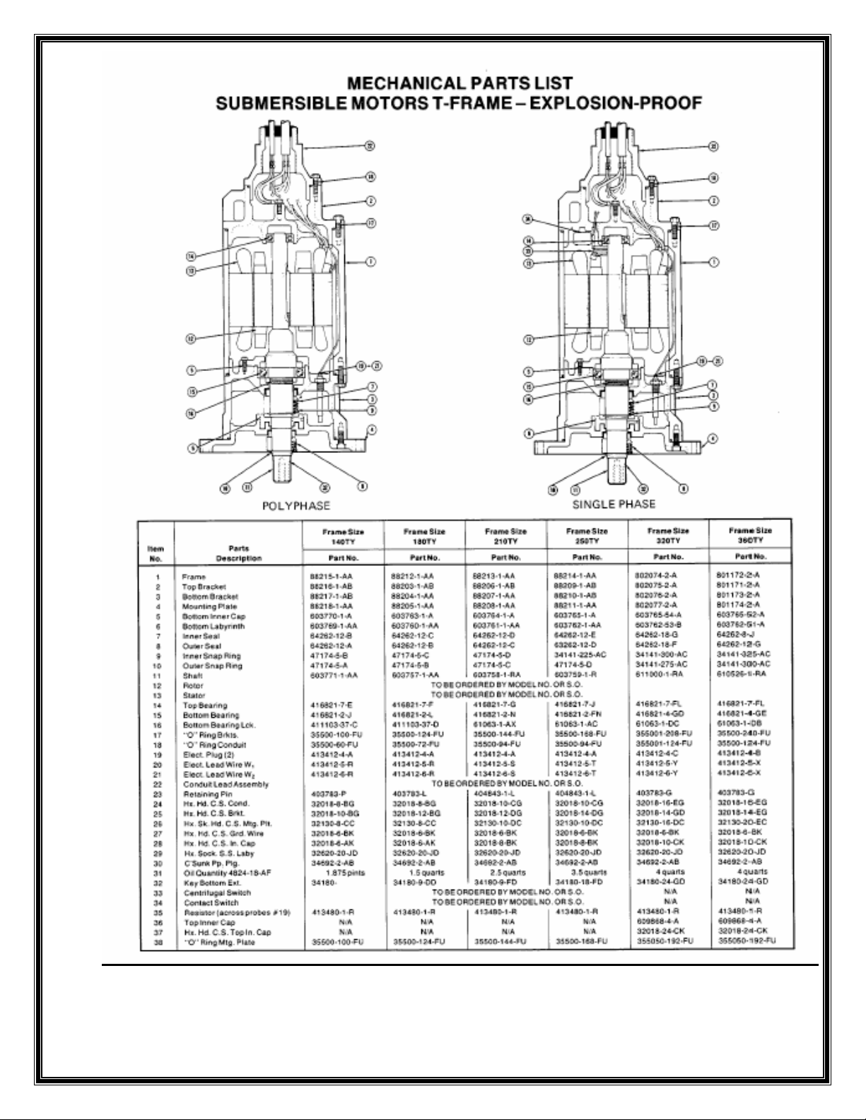
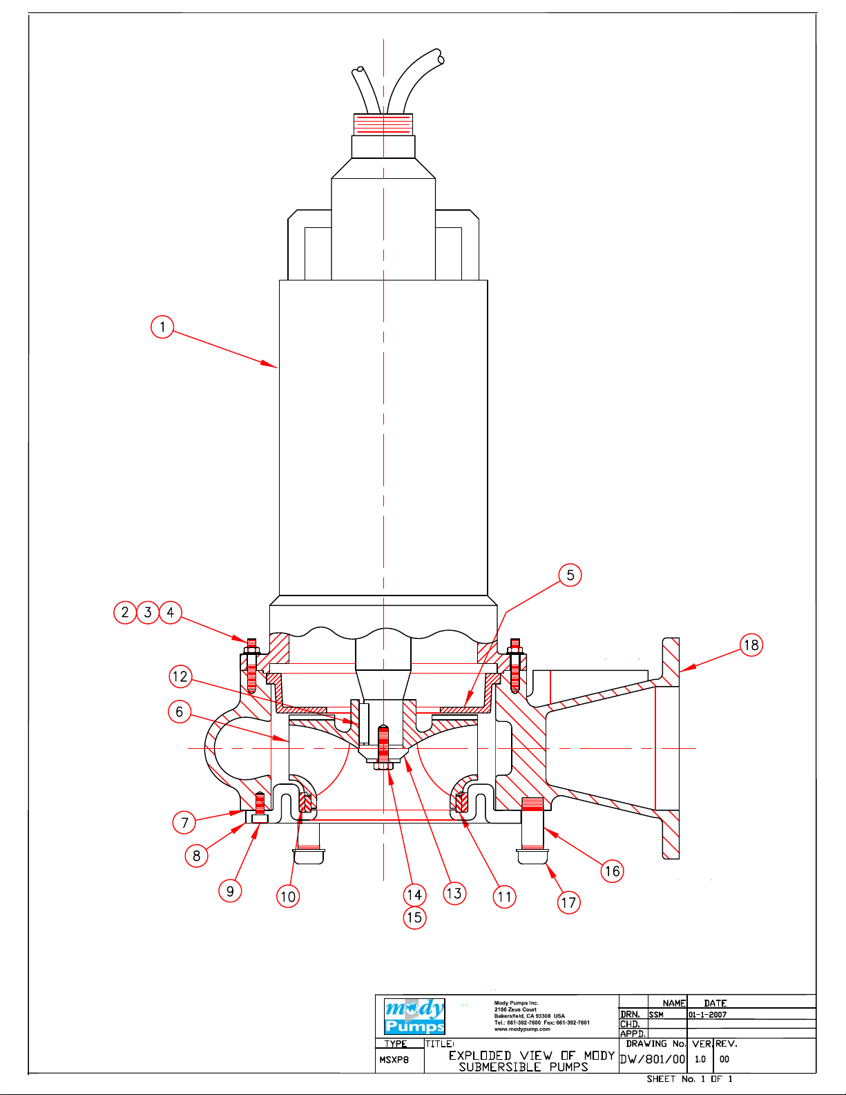
DIS-ASSEMBLY(REFER DRG.NO.DW/801/00
• IT IS MANDATORY THAT ALL "O" RINGS BE REPLACED WHENEVER A PUMP IS OVERHAULED
OR DISMANTLED. UNDER NO CIRCUMSTANCES SHOULD OLD "O" RINGS BE USED, EVEN IF
THEY SEEM O.K. BE CAREFUL NOT TO SCRATCH SEALING SURFACES. ALWAYS GREASE NEW
“O” RINGS BEFORE INSTALLATION.
• ALWAYS ISOLATE THE UNIT FROM ELECTRICAL POWER BEFORE ATTEMPTING ANY
OVERHAUL.
• THE PERMANENT INSTALLATION VERSION IS SUPPLIED WITH A SLIDING BRACKET FIXED
ON THE VOLUTE OF THE PUMP. LAY THE PUMP ON IT’S SIDE ON A BENCH OR OVER TWO
SUPPORTS.
• UNSCREW NUTS (4) AND REMOVE PUMP VOLUTE (18) FROM MOTOR FLANGE AND BACKPLATE
(5). REMOVE CAP SCREW AND LOCK WASHER (14 & 15) OR IN CASE OF 1150 RPM MOTOR
HEX NUT. SLIDE IMPELLER OF THE MOTOR SHAFT. IF THE IMPELLER IS SLIGHTLY
TIGHT USE A WOODEN MALLET TO TAP THE SAME OFF THE SHAFT. REMOVE KEY (12).
KEEP ASIDE CAREFULLY.
• THE LOWER MECHANICAL SEAL IS NOW IN VIEW. BE CAREFUL. IF THE SEAL HAS
LEAKED, THE OIL CASING MAY BE UNDER PRESSURE. USING A NOSE/CIRCLIP PLIER
REMOVE SNAP RING. THE MECH. SEAL ASSEMBLY CAN NOW BE REMOVED FROM THE SHAFT
BY HAND. BE VERY CAREFUL WITH THE SEALING SURFACES SO THAT THEY DO NOT
SUFFER DAMAGE OR GET SCRATCHED IN ANY WAY. LEAVE THE SEAL SEAT IN THE SEAL
HOUSING.
• EXAMINE IMPELLER, WEAR RING FOR WEAR. CHECK CONDITION OF OIL. IF EMULSIFIED
AND CONTAMINATED REPLACE OUTER MECHANICAL SEAL. IF OIL CHAMBER IS FULL OF
PUMPED FLUID WE RECOMMEND CHANGING BOTH MECHANICAL SEALS INNER AND OUTER.
• IF THE WEAR RING NEEDS TO BE REPLACED REMOVE CAP SCREWS (9) AND SEPARATE THE
SUCTION COVER. JACK OUT THE WEAR RING USING THE PRETHREADED BOLT HOLES AT
THE BOTTOM OF THE SUCTION COVER.
Page 9
RE- ASSEMBLY OF THE PUMPSET.
THE PUMP CAN BE RE- ASSEMBLED BY REVERSING THE ABOVE PROCEDURE. PLEASE HOWEVER
NOTE THE FOLLOWING:
• ALWAYS REPLACE ELASTOMER ELEMENTS.
• REPLACE LOCK WASHER DURING RE –ASSEMBLY.
• LIGHTLY OIL (DO NOT USE GREASE) OUTER SURFACE OF STATIONARY SEAT & PRESS IT
GENTLY INTO MOUNTING PLATE USING A SEAL PUSHER. NOTE WORK STATION SHOULD BE
ABSOLUTELY CLEAN NOT ALLOWING FOREIGN MATTER TO COME IN CONTACT WITH SEAL
FACES. MAKE SURE THE STATIONARY SEAT IS FLUSH AND STRAIGHT. THE O RING
SHOULD BE IN IT’S GROOVE AND NOT PINCHED.
• LIGHTLY OIL SHAFT(DO NOT USE GREASE) AND INNER SURFACE OF BELLOWS ON
ROTATING FACE. SLIDE ROTATING FACE ONTO SHAFT USING A SEAL PUSHER.
OIL SPECIFICATIONS
A) SUN OIL COMPANY – SUN FLEET REGULAR SAE 10W
B) SHELL – ROTELLA 10SAE 10W
C) STANDARD OIL COMPANY – SOHIO 62SAE 10W
PLEASE NOTE THE SEAL CHAMBER CONTAINS APPROX. 2.5 LITRES OF OIL.
Page 10
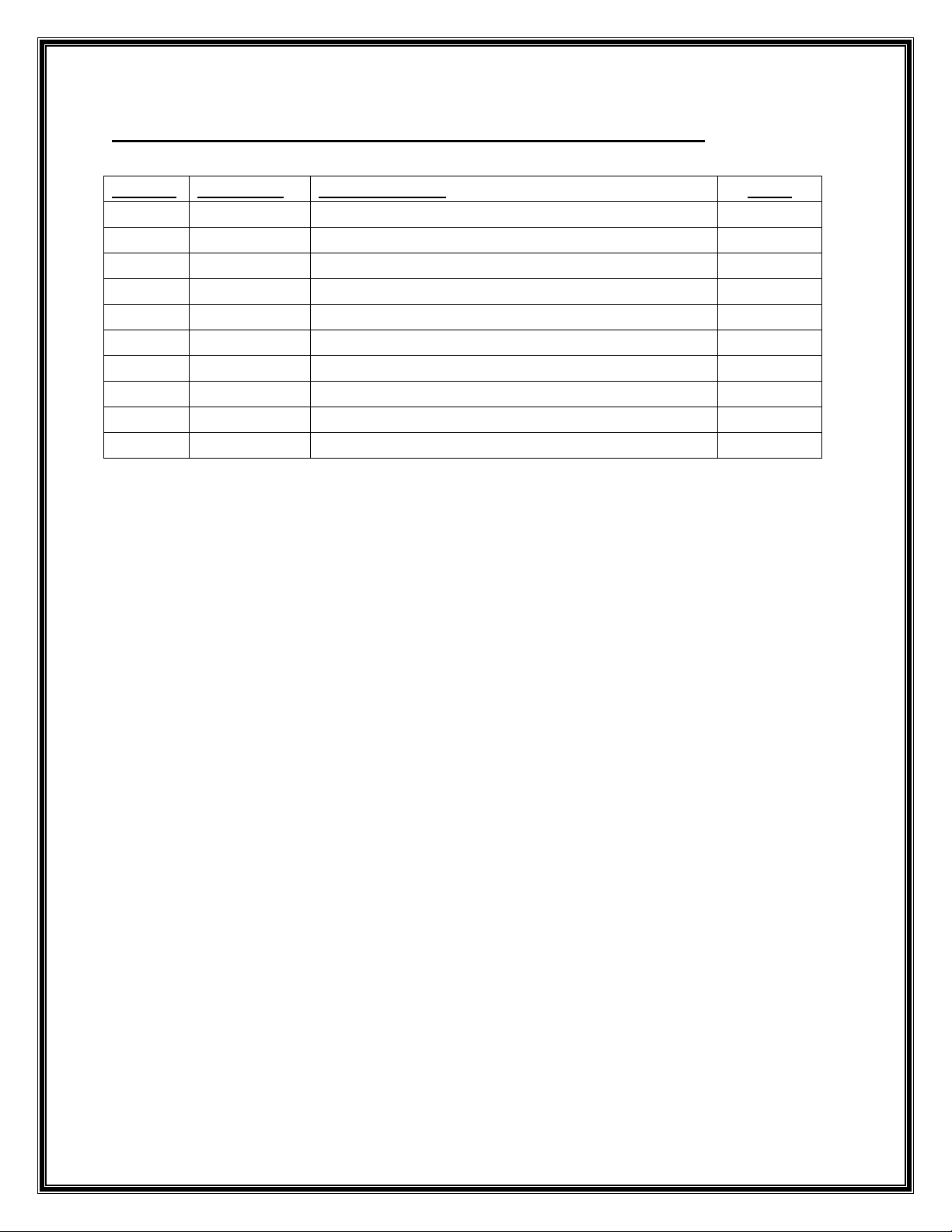
RECOMMENDED SPARES FOR TWO YEARS OPERATION:
SR. NO. PART NO. DESCRIPTION QTY.
1a 535-210-00 OUTER MECHANICAL SEAL 210TY FRAME 1
1b 535-250-00 OUTER MECHANICAL SEAL 250TY FRAME 1
1c 535-320-00 OUTER MECHANICAL SEAL 320TY FRAME 1
1d 535-360-00 OUTER MECHANICAL SEAL 360TY FRAME 1
2a 375-210-66 “O” RING SET 210TY FRAME 1
2b 375-250-66 “O” RING SET 250TY FRAME 1
2c 375-320-66 “O” RING SET 320TY FRAME 1
2d 375-360-66 “O” RING SET 360TY FRAME 1
3 300-800-01 IMPELLER 60Hz SPECIFY TRIM 1
4 720-801-45 WEAR RING 1
Page 11
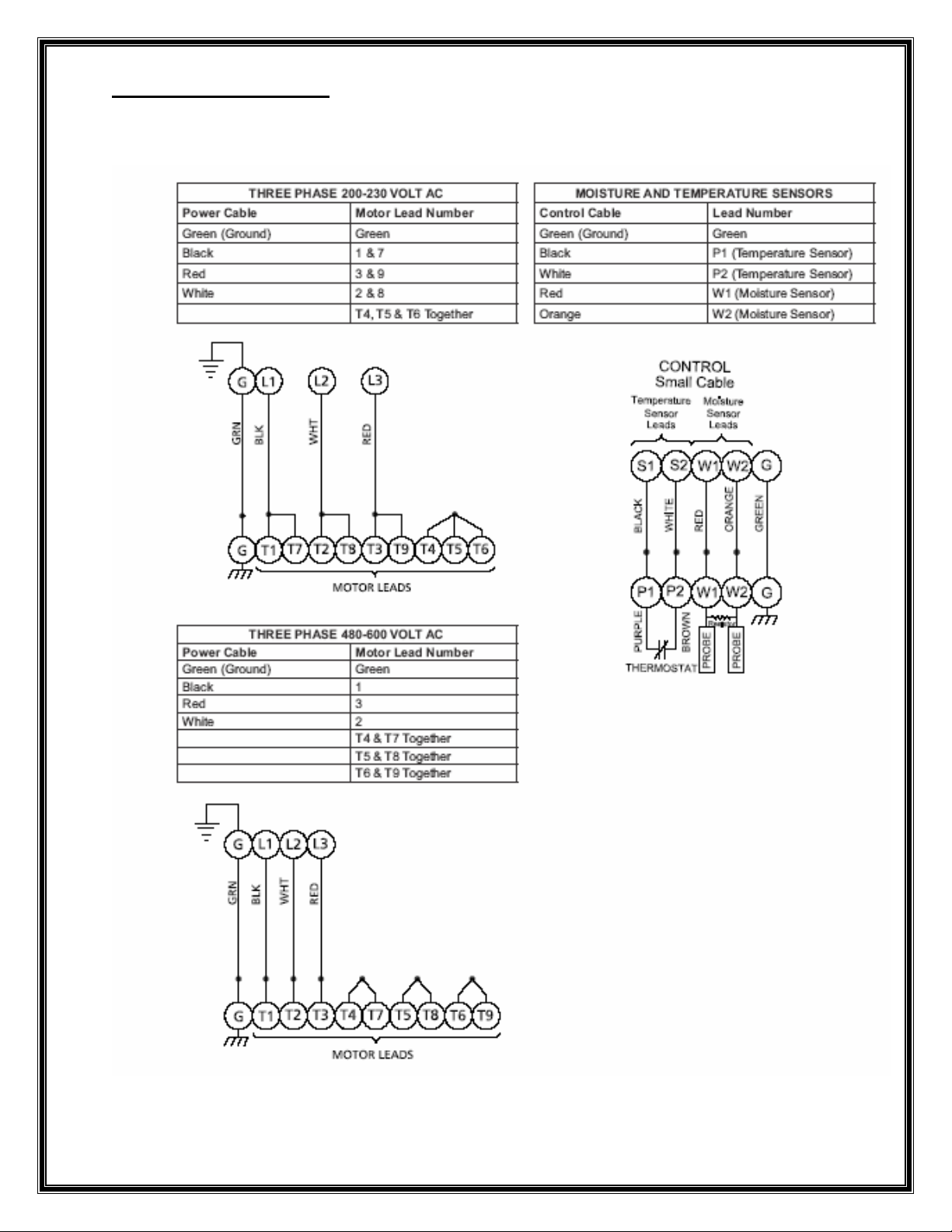
WIRING DIAGRAMS:
Page 12
Page 13
C US
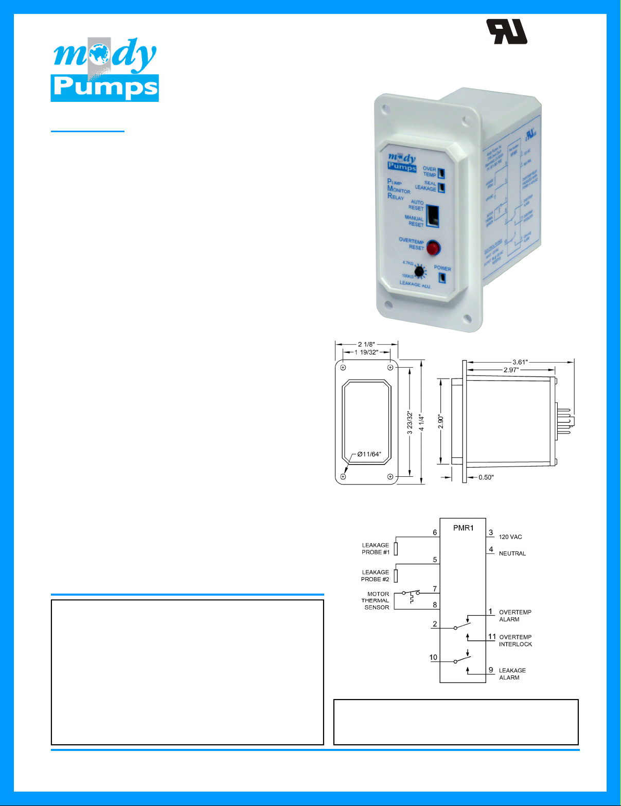
Pump Monitor Relay
OPERATION
The MPMR provides Motor Over Temperature and Seal
Leakage alarm for Mody Submersible Pumps.
Motor Over Temperature Alarm - The unit applies a low
voltage DC signal to the Motor Thermal Sensor to check its
status. If the unit detects that the Motor Thermal Sensor
contacts are closed (normal condition), the Overtemp
indication remains off, and the Overtemp Relay is
energized closing the contacts between terminals 2 and 11.
If the Motor Thermal Sensor contacts open (Over
Temperature condition), the Overtemp Indication is turned
on and the Overtemp Alarm Relay is de-energized opening
the contacts between terminals 2 and 11 and closing the
contacts between terminals 2 and 1.
When the High Motor Temperature condition has cleared,
the unit will reset based on the position of Alarm Reset
Mode Select Switch (Auto or Manual). When in the Auto
position, the Overtemp Alarm resets automatically. If the
switch is in the Manual position, the Overtemp Reset Pushbutton must be pushed for approximately 1.5 seconds to
clear the alarm.
Seal Leakage Alarm - The unit detects moisture inside a
pump motor by using a low voltage AC signal to measure
the resistance across Leakage Probes #1 and #2, or
between Leakage Probe #1 and the grounded motor
housing. A Seal Leakage condition is considered present
when the amount of moisture in the motor causes the
resistance between terminals 6 and 5 to drop below the
setting on the potentiometer. When this occurs the unit
turns on the Leakage Indication and energizes the Leakage
Alarm Relay closing the contacts between terminals 9 and
10.
The alarm trip point may be set by the following procedure:
Isolate the Leakage Probe from terminal 6. Connect a
resistor, with the desired trip value, across terminals 5 and
6. Slowly adjust the potentiometer to the point where the
alarm turns on. Remove the resistor and reconnect the
Leakage Probe to terminal 6.
MADE IN THE U.S.A.
UL FILE #E101681
SPECIFICATIONS
Input Power:
Output Rating:
Operating Temp:
Storage Temp:
Temp Sensor Voltage:
Leak Sensor Voltage:
Enclosure:
Base:
120 VAC ±10%, 7.0 VA max
8A Resistive @ 120VAC
-20°C to +65 °C
-45°C to +85 °C
6.6 VDC ±10%
4.7 VAC ±10%
White Lexan, NEMA 1
Phenolic
ORDERING INFORMATION
Part Number: 660-901-00
Mody Pumps, Inc. • 2166 Zeus Court, Bakersfield, CA 93308 USA
Tel. (661) 392-7600 Fax: 661-392-7601
www.modypump.com email: [email protected]
08.10.Rev.0
Page 14
RETURNED GOODS POLICY:
RETURN OF MERCHANDISE REQUIRES A “RETURNED GOODS
AUTHORIZATION” OR RGN NUMBER. CONTACT YOUR LOCAL MODY
PUMPS INC. DISTRIBUTOR OR THE FACTORY DIRECTLY.
PRODUCTS THAT ARE RETURNED MUST BE PRESSURE WASHED,
CLEANED, SANITIZED AND DECONTAMINATED AS NECESSARY PRIOR
TO SHIPMENT. THIS ENSURES THAT EVERYONE IN CONTACT WITH
RETURNED UNITS ARE NOT EXPOSED TO HEALTH HAZARDS. ALL
APPLICABLE LAWS AND REGULATIONS SHALL APPLY.
Page 15
Page 16
Page 17
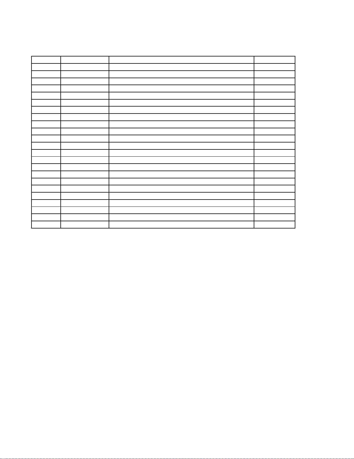
PUMP MODEL MSXP8 1/1/2011
#
D.NO. PART
1 RELIANCE MOTOR 1
2 650-801-21 STUD 16
3 695-801-21 LOCKWASHER 16
4 370-801-21 HEX NUT 16
5 715-801-01 BACKPLATE 1
6 300-800-01 IMPELLER (SPECIFY TRIM) 1
7 220-801-66 GASKET 1
8 155-801-01 SUCTION COVER 1
9 520-801-01 CAP SCREW 8
10 720-801-45 WEAR RING 1
11 720-802-45 IMPELLER RING (1750 RPM) 1
12 320-801-21 IMPELLER KEY 1
13 695-802-21 IMPELLER WASHER (1750 RPM) 1
14A 520-802-21 CAP SCREW (1750 RPM) 1
14B 370-802-21 HEX NUT (1150 RPM) 1
15 695-802-21 IMPELLER LOCKWASHER 1
16 030-801-01 PIPE NIPPLE 1
17 030-802-01 PIPE CAP 4
18 050-801-01 VOLUTE 4
19a 535-210-00 OUTER MECHANICAL SEAL (SC/SC) FRAME 210 1
19b 535-250-00 OUTER MECHANICAL SEAL (SC/SC) FRAME 250 1
19c 535-320-00 OUTER MECHANICAL SEAL (SC/SC) FRAME 320 1
19d 535-360-00 OUTER MECHANICAL SEAL (SC/SC) FRAME 360 1
DESCRIPTION QTY
Page 18
LIMITED WARRANTY
We warrant to our immediate customer and to the ultimate consumer that products of our manufacture will be free
of defects in material and workmanship under normal use and service for the following time periods, when installed
and maintained in accordance with our instructions.
PUMPS: One (1) year from date of installation or (18) months from date of shipment, whichever occurs first. As
used herein, “the ultimate consumer” is defined as the purchaser who first uses the product after it’s initial
installation or, in the case for product designed for non-permanent installation, the first owner who uses the product.
It is the purchaser’s or any sub-vendor’s obligation to make known to the ultimate consumer the terms and
conditions of this warranty. This warranty gives you specific legal rights, and there may also be other rights which
vary from state to state. In the event the product is covered by the Federal Consumer Product Warranties Law (1)
the duration of any implied warranties associated with the product by virtue of said law is limited to the same
duration as stated herein, (2) this warranty is a LIMITED WARRANTY, and (3) no claims of any nature
whatsoever shall be made against us, until the ultimate consumer, his successor, or assigns, notifies us in writing of
the defect, and delivers the product and/or defective part(s) freight prepaid to our facility or nearest authorized
service station. Some states do not allow limitations on how long an implied warranty lasts, so the above limitation
may not apply. THE SOLE AND EXCLUSIVE REMEDY FOR BREACH OF ANY AND ALL
WARRANTIES WITH RESPECT TO ANY PRODUCT SHALL BE TO REPLACE OR REPAIR AT OUR
ELECTION, FOB POINT OF MANUFACTURE OR AUTHORIZED REPAIR STATION, SUCH
PRODUCTS AND/OR PARTS AS PROVEN DEFECTIVE. THERE SHALL BE NO FURTHER
LIABILITY, WHETHER BASED ON WARRANTY, NEGLIGENCE OR OTHERWISE. Unless expressly
stated otherwise, guarantees in the nature of performance specifications furnished in addition to the foregoing
material and workmanship warranties on a product manufactured by Mody Industries Pvt. Ltd., if any, are subject to
laboratory tests corrected for field performance. Any additional guarantees, in the nature of performance
specifications must be in writing and such writing must be signed by our authorized representative. Due to
inaccuracies in field testing if a conflict arises between the results of field testing conducted by or for user, and
laboratory tests corrected for field performance, the latter shall control. Components or accessories supplied by us
but manufactured by others are warranted only to the extent of and by the terms and conditions of the original
manufacturer’s warranty. RECOMMENDATIONS FOR SPECIAL APPLICATIONS OR THOSE
RESULTING FROM SYSTEMS ANALYSES AND EVALUATIONS WE CONDUCT, WILL BE BASED
ON OUR BEST AVAILABLE EXPERIENCE AND PUBLISHED INDUSTRY INFORMATION. SUCH
RECOMMENDATIONS DO NOT CONSTITUTE A WARRANTY OF SATISFACTORY
PERFORMANCE AND NO SUCH WARRANTY IS GIVEN.
This warranty shall not apply when damage is caused by (a) improper installation, (b) improper voltage, (c)
lightning, (d) sand or other abrasive materials, (e) scale or corrosion build-up due to excessive chemical content.
Any modification of the equipment will also void the warranty. We will not be responsible for loss, damage or labor
cost due to interruption of service caused by defective parts. Neither will we accept charges incurred by others
without our prior written approval. This warranty is void if our inspection reveals the product was used in a manner
inconsistent with normal industry practice and/or our specific recommendations. The purchaser is responsible for
communication of all necessary information regarding the application and use of the product. UNDER NO
CIRCUMSTANCES WILL WE BE RESPONSIBLE FOR ANY OTHER DIRECT OR CONSEQUENTIAL
DAMAGES, INCLUDING BUT NOT LIMITED TO LOST PROFITS, LOST INCOME, LABOR
CHARGES, DELAYS IN PRODUCTION, IDLE PRODUCTION, WHICH DAMAGES ARE CAUSED BY
ANY DEFECTS IN MATERIAL, AND/OR WORKMANSHIP AND/OR DELAYS IN SHIPMENT. THIS
WARRANTY IS EXPRESSLY IN LIEU OF ANY OTHER EXPRESS OR IMPLIED WARRANTY,
INCLUDING ANY WARRANTY OF MERCHANTABILITY OR FITNESS FOR A PARTICULAR
PURPOSE.
No rights extended under this warranty shall be assigned to any person, whether by operation or otherwise, without
our prior written approval.
Mody Pumps Inc.: 2166 Zeus Court, Bakersfield, CA 93308 Tel.: (661) 392-7600 Fax: (661) 392-7601
 Loading...