

modway EEI -1328 User Manual
Customer Service 908-368-1025︱︱︱︱www.modwayfurniture.com Page 1 of 8
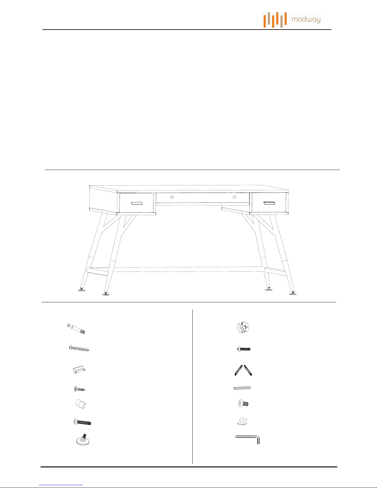
EEI -1328 DESK
Hardware:
Thank you for purchasing the MODWAY DESK!!!!
Before you start, here is some helpful advice:
1.We suggest you spend a short time reading through this leaflet and then follow the simple step by step
instructions.
2.Owing to the size and weight of the desk, we recommend that it is assembled by two adults, on a carpeted or
padded area, in the room that it is intended for. Approximate assembly time: 45 minutes.
3.Please do not use any tools other than those provided or recommended in these instructions.
4.Please do not throw away any of the packaging or instructions until you have checked all the components and
hardware and the furniture is fully assembled.
5.Assemble all components loosely until advised to tighten. Depending on use, it may be necessary to tighten the
components from time to time, so please save the tools that have been provided.
6.Please keep all pieces out of reach of small children.
a
Cam x30
b
Cam Post x30
c
Screw M4x35mm x12
d
Pull Screw M4x20mm x6
e
Pull x2
f
Drawer Guides x3 sets
g
Screw M4x14mm x30
h
Dowel x32
j
Knob x2 k
Bolt M6x12mm x12
m
n
Drawer Bottom Holder x6
p
Allen Wrench x1
Bolt M6x50mm x2
m
Leveler x4
Customer Service 908-368-1025︱︱︱︱www.modwayfurniture.com Page 2 of 8
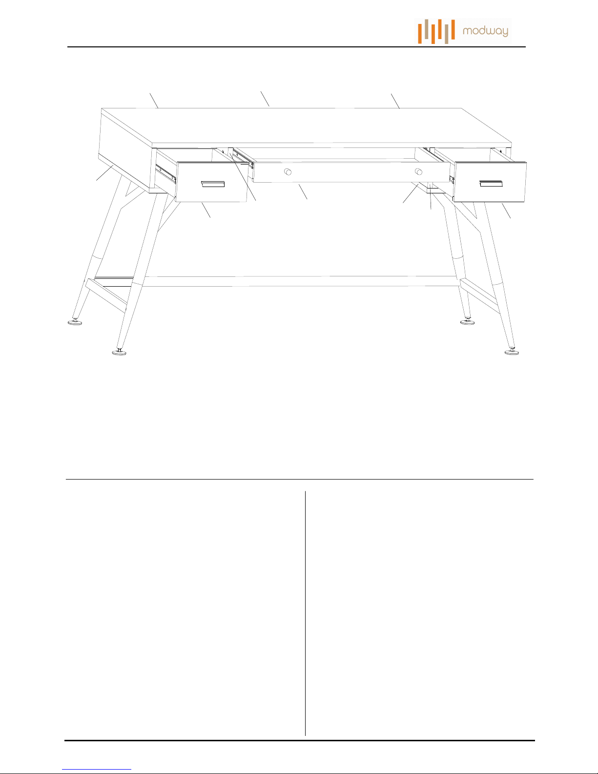
EEI -1328 DESK
Component:
A
Top Panel x1
B
Left Side Panel x1
A
C
Right Side Panel x1
D
Left Divide Panel x1
E
Right Divide Panel x1
F
Left Bottom Panel x1
G
Center Bottom Panel x2
H1
Side Drawer Front x2
H2
Side Left Drawer Side x2
H3
Side Right Drawer Side x2
H4
Side Drawer Back x2
H5
Side Drawer Bottom x2
J1
Center Drawer Front x1
J2
Center Left Drawer Side x1
J3
Center Right Drawer Side x1
J4
Center Drawer Back x1
J5
Center Drawer Bottom x1
K
Side Back Panel x2
L
Center Back Panel x1
M
Left Leg x1
N
Right Leg x1
B
C
F
D
E
G
H
H1
H1
J1
M
N
P
H2
H3
H4
H5
H5
H3 H4
H2
J2 J3
J4
J5
L
K
K
P
Bottom Rail x1
Customer Service 908-368-1025︱︱︱︱www.modwayfurniture.com Page 3 of 8
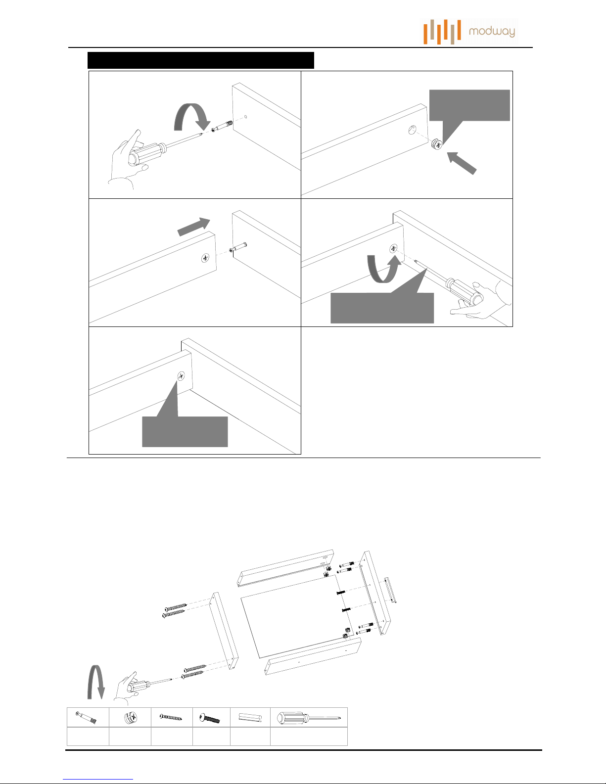
EEI -1328 DESK
HOW TO USE CAN AND CAM POST HARDWARE
STEP 1:
1. 2.
3.
4.
Note cam arrow
direction
Note cam arrow
direction
Turn cam clockwise
1/2 turn
5.
Place 1pc Side Drawer Front (H1),1pc Side Drawer Back (H4),1pc Left Drawer Side (H2), 1pc Right Drawer Side (H3)
and 1pc Side Drawer Bottom (H5) together as shown.
Attach them by 2pcs Cam Post (a), 2pcs Cam (b), 4pcs Screw (c), tighten the Screws (c) and Cam (b)
Attach 1pc Pull (e) to the Side Drawer Front (H1) by using 2pcs Pull Screw (d).
Fully tighten Cams (b), Screws (c), Pull Screws (d) with Phillips Head Screw Driver (not included).
Repeat the same steps and hardware for the other Side Drawer.
ax4 bx4 cx8
dx4
ex2
Phillips Head Screwdriver
( not included)
Hardware & Tools required
h
H1
d
H2
H3
H4
H5
a
a
b
b
c
c
d
e
 Loading...