

Page 1
GE
Sensing
Modus W Series
Modus W Series is a General Eastern
product. General Eastern has joined
other GE high-technology sensing
businesses under a new name—
GE Industrial, Sensing.
g
General Eastern Liquid
Differential Pressure
Transmitters
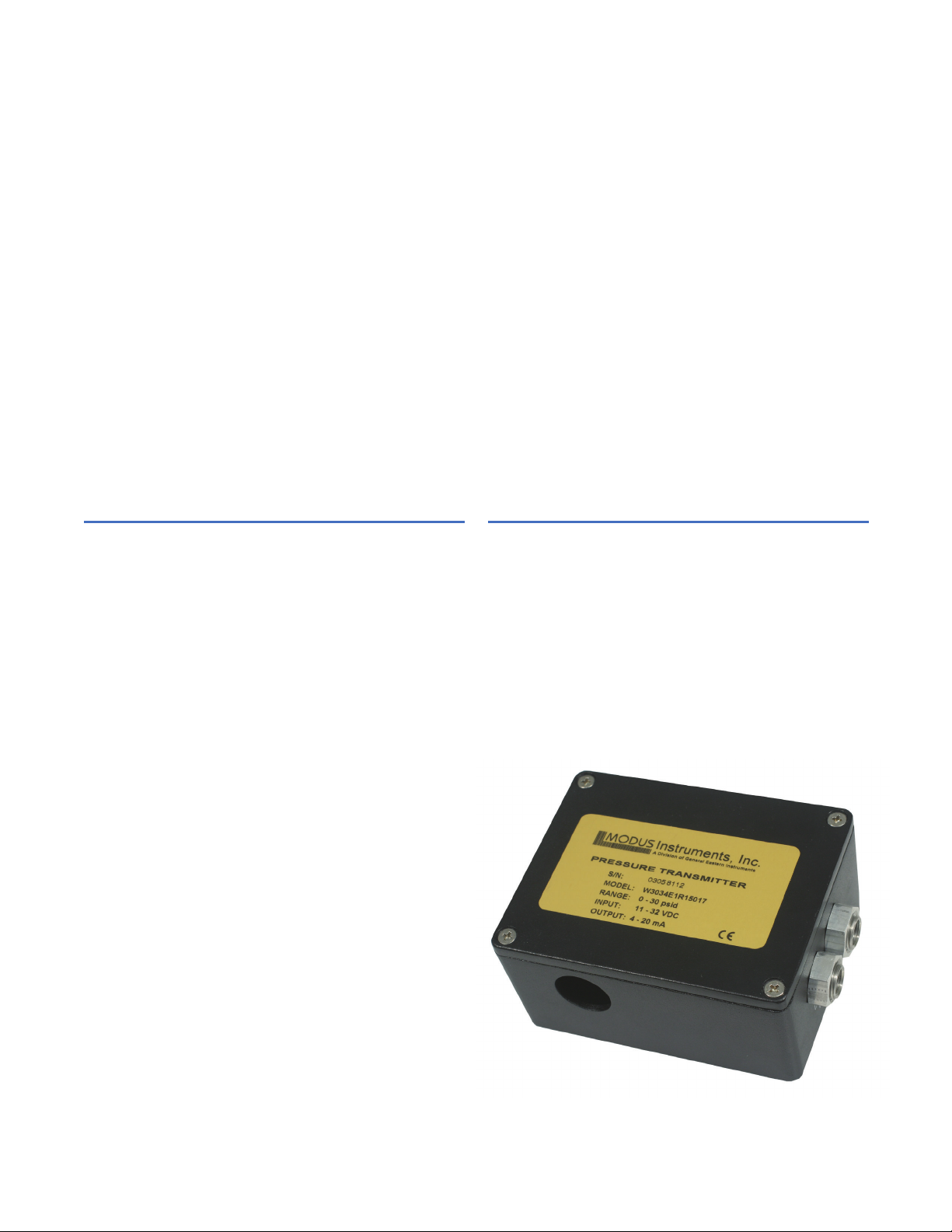
The Modus W Series pressure transmitters are designed
to measure low differential pressures of liquids or gases.
A wide selection of standard pressure ranges and
electrical ratings is available.
These transmitters feature no moving parts to wear out,
a proven long term stability of piezoresistive devices, only
316 stainless steel in contact with the fluid, and an
all-welded construction.
Modus W Series transmitters are an excellent choice for
many HVAC, process and automation monitoring
requirements. Typical applications include measurement
of differential pressure across flow elements, heat
exchangers, pumps and filters, liquid level monitoring
and other demanding differential pressure measurement
and control applications.
The transmitters are housed in a compact, heavy duty,
gasketted, cast aluminum enclosure designed to IP 65 of
IEC 529 standards and Type 4. The die cast aluminum
enclosure incorporates a recessed neoprene gasket to
prevent the ingress of moisture or dust. Wall mounting
holes are enclosed in the cast aluminum box and
concealed by the cover. The wall mounting holes and the
cover attaching screws are outside the gasketted area.
Access to the electrical terminals are made through
knockouts on the front of the box. A choice of two
knockouts and three hole sizes are available to
accommodate usage of 0.5 in (12.7 mm) conduit or
metric sizes PG11 and PG13.
Pluggable terminal block connectors are provided with
wire protection and captive terminal screws.
The Modus W Series includes one model: Model W30.
Page 2

This model is available with the following power and
signal configuration
Model W30
• Two-wire
• DC Voltage In
• 4 to 20 mA out
The span or zero adjustment is performed with a 20-turn
potentiometer for fine resolution. A 50% adjustment in
output is possible.
The Series W transmitters comply with the European
requirements of Council Directive 89/336/EEC.
GE
Sensing
Operation
The pressure transmitter consists of two high accuracy
piezoresistive sensors with stainless steel isolation
diaphragms. Both sensors measure static pressure, and
the difference between these two measurements is
computed electronically. The use of high accuracy and
stable sensors makes this measurement possible. Since
each sensor measures the full static pressure, there is no
possibility of over-pressurizing the transmitter if one
sensor is disconnected from the line. No complex and/or
expensive balancing valves are needed.
Page 3

W Series
Specifications
Performance
Accuracy
±1/2% of differential pressure range (includes
non-linearity and hysteresis) or ±1% for 6 psid (50 kPA)
range
Effect of Static Pressure on Differential
Pressure Measurement
Less than ±0.25% for static pressure change from 0 to
100% or ±0.5% for 6 psid (50 kPa) range
Calibration
Traceable to National Institute of Standards and
Technology (NIST)
Environmental
Process wetted surfaces are 316 stainless steel.
Operating Temperature Range
32°F to 122°F (0°C to 50°C)
Storage Temperature
-20°F to 160°F (-30°C to 70°C)
Effect of Temperature
• On zero: ±0.05%/°C or ±0.1%/°C for 6 psid (50 kPa)
range
• On span: ±0.03%/°C or ±0.06%/°C for 6 psid (50 kPa)
range
Operating Humidity Range
10% to 90% RH, non-condensing
Shock Resistance
10 G (11 ms)
Vibration Resistance
5 G 3 to 50 Hz
Electrical Connectors
Polarized Euro plug/connectors.
Connections
Pluggable terminal block for wire 14 to 26 AWG.
Mating connector is supplied
Connection to enclosure ground is provided.
Connector rating
10 Amps/300 V
Material
Glass-filled polyester
Physical
Dimensions
3.56 in x 4.54 in x 2.18 in (90 mm x 115 mm x 55 mm)
Enclosure material
Aluminum Alloy #A380
Cover screws
M4 stainless steel non-magnetic
Finish
Black epoxy paint
Knockout
• Choice of 2 holes
• Hole sizes are offered in a choice of 1/2 in (12.7 mm)
conduit or metric sizes of PG11 or PG13.
• Cable glands not included.
Pressure port connections
1/8-28 female NPT
Weight
1.2 lb (540 g)
GE
Sensing
Page 4
g
©2006 GE. All rights reserved.
920-301A
All specifications are subject to change for product improvement without notice.
GE
®
is a registered trademark of General Electric Co. Other company or product
names mentioned in this document may be trademarks or registered trademarks
of their respective companies, which are not affiliated with GE.
Electrical
Supply Voltage
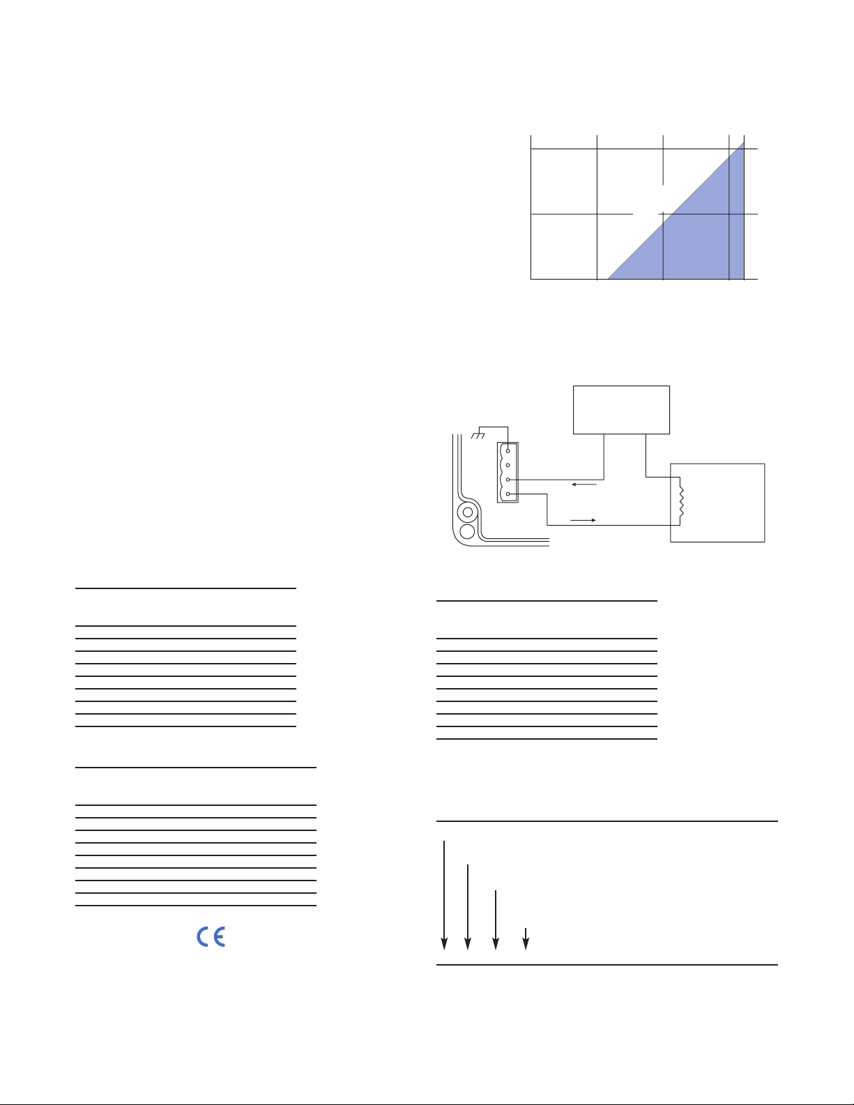
11 to 32 VDC (See diagram for maximum loop resistance)
Output
Two-wire/4 to 20 mA output
Protected against reversal of polarity. Output limited to
approximately 3.85 mA at low end of span and
approximately 25 mA at upper end of span.
US Units
Pressure Differential Operating Static
Code Pressure Range, Pressure,
psid psi
31E 0 to 6 psi
32E 0 to 10 psi 0 to 100 psi
33E 0 to 15 psi
34E 0 to 30 psi
35E 0 to 60 psi
36E 0 to 100 psi 0 to 300 psi
37E 0 to 150 psi
38E 0 to 200 psi
W30 Series
Specifications
GE
Sensing
Metric Units Pascal
Pressure Differential Operating Static
Code pressure Range, Pressure
kPA kPa
31P 0 to 50 Pa
_
32P 0 to 75 Pa 0 to 700 kPa*
33P 0 to 100 Pa
_
34P 0 to 200 Pa
_
35P 0 to 500 Pa
_
36P 0 to 750 Pa 0 to 2000 kPa
37P 0 to 1000 Pa
_
38P 0 to 1500Pa
_
Metric Units, Millimeters of Water
Pressure Differential Operating Static
Code Pressure Range, Pressure,
k mm H2O k mm H2O
31M 0 to 5.0 k mm H20
_
32M 0 to 7.5 k mm H20 0 to 70 k mm H20
33M 0 to 10 k mm H20
_
34M 0 to 20 k mm H20
_
35M 0 to 50 k mm H20
_
36M 0 to 75 k mm H20 0 to 200 k mm H20
37M 0 to 100 k mm H20
_
38M 0 to 150 k mm H20
_
Ordering Information
Record selected option in blank indicated at bottom of form.
W30
Code Pressure Range (PPP)
X See Standard Pressure Ranges Tables
Code Knockout Quantity (KQ)
2 Two holes
Code Knockout Size (KS)
R 1/2 in (12.7 mm) conduit
S PG 11
W30 -___ - ___ - ___ Typical model number.
Standard Pressure Ranges for
Modus W Series
c
Modus W30 Series schematic diagram
1000
500
1
Loop Resistance (
SS
)*
0102030
Power Supply Voltage
*Loop resistance = wire resistance + receiver resistance
Operating
Region
Maximum Resistance
Power Supply
+
_
Wire
Wire
_
+
Receiver
0 to 1050 S
Enclosure
Ground
1
2
3
4
www.gesensing.com
+
-
to 32 Vd
 Loading...