

Page 1
Amphenol
Advanced Sensors
Series T
Differential Pressure
Transmitters
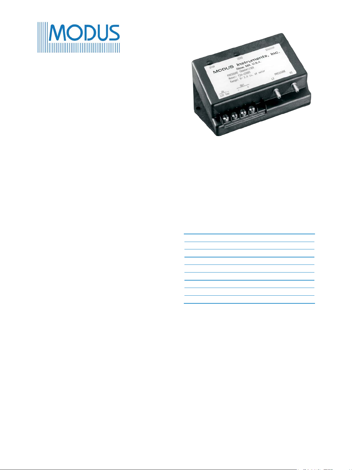
The Modus Series T family of differential
pressure transmitters measure low pressures
and feature low power consumption and
a variety of analog signal outputs. A wide
selection of standard pressure ranges and
electrical ratings is available.
These transmitters feature: no moving parts to
wear out, reliable long term stability, and are
virtually position insensitive.
The Series T Transmitters are an excellent
choice for many HVAC, process and
automation monitoring requirements.
These transmitters monitor: lter differential
pressures, fan static pressures, clean room
pressures, variable air volume systems and
velocity pressures. They have been used for
bubbler level systems, leak detection and in
medical and analytical instruments.
The transmitters are housed in a ame
retardant, glass-reinforced polyphenylene oxide
(NORYL™) case. Electrical connections are
made by means of a 3/8 in terminal strip with
#6 screws.
The Series T includes three models: Model
T10, Model T20, and Model T30. These three
models incorporate a variety of power and
signal options.
The span or zero adjustment is performed with
a 20-turn potentiometer for ne resolution.
T10 Three-wire
DC Voltage In
DC Voltage Out
T20 Four-wire
24, 120, or 240 VAC In
DC Voltage Out
T30 Two-wire
DC Voltage In
4 to 20 mA Out
The piezoresistive sensor is a solid state device
designed in a Wheatstone bridge conguration.
When pressure is applied to the device, the
resistance of the bridge changes by a small
amount. This resistance change is converted to
a voltage and amplied.
Page 2

Series T Specications
General
• Measures differential, gage pressure, or vacuum
• Suitable for air or inert gases
• Maximum safe momentary overpressure: see
reference table A
Performance
Accuracy
± 1% of span (including non-linearity and hysteresis)
Calibration
(Traceable to NIST)
Environmental
Operating Temperature Range
32°F to 115°F (0°C to 45°C)
Storage Temperature
-20°F to 160°F (-30°C to 70°C)
Effect of Temperature
• on zero: ±0.05%/°C
• on span: ±0.02%/°C
Operating Humidity Range
10% to 90% RH
non-condensing
Shock Resistance
10 G (11 ms)
Vibration Resistance
5 G to 50 Hz
Electrical Connections
Connections
External 3/8 in terminal strip with #6 screws
Physical
Pressure Port Connections
3/16 in diameter suitable for:
• 1/8 in ID Tygon™ or polyurethane tubing
0.11 in to 0.15 in (3 mm to 4 mm)
• 1/4 in OD polyethylene tubing (6 mm)
Integral lters at both ports
Dimensions (W x L x H)
3.00 in x 5.15 in x 1.40 in
(76 mm x 131 mm x 36 mm)
Material
Flame retardant, glass-reinforced polyphenylene
oxide (NORYL) case
Weight
0.42 lbs (190 g) maximum
2
Page 3
Model T10 Specications
Power S
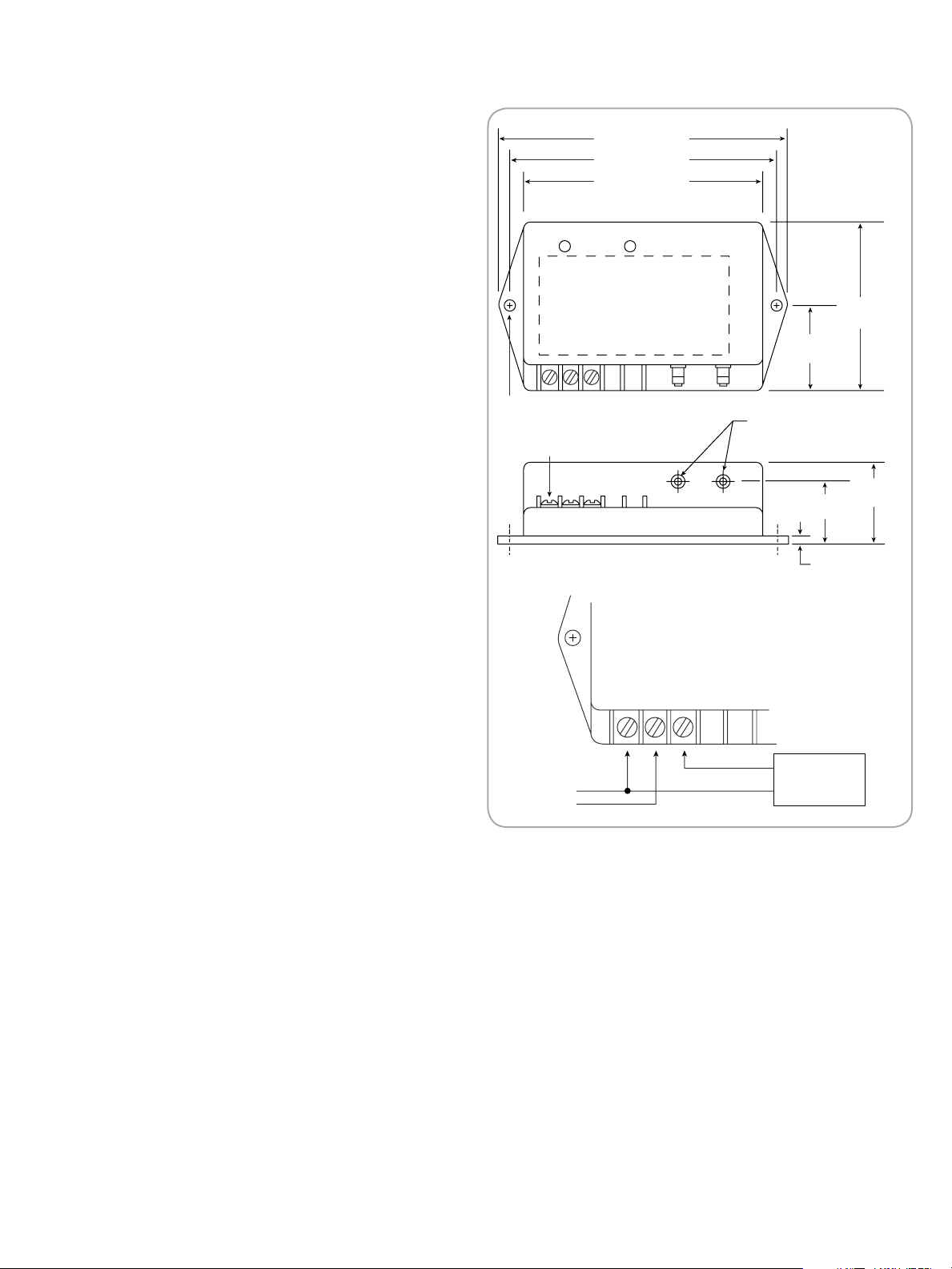
5.13 in (130 mm)
DC Power Input/Voltage Output
Diagram shows area of detail.
Please see inset diagrams for wiring.
Electrical
4.75 in (121 mm)
4.24 in (108 mm)
Supply Voltage
11 to 32 VDC (14.5 to 32 VDC for 10 Volts output)
Protected against reversal of polarity
Supply Current
10 mA
Output
• 0 to 5 Volts, linear
• 0 to 10 Volts, linear
• Sink or source 3.5 mA
• Protected against short circuit
Ordering Information
Order Number
(See Table below and Reference Table A)
T10 - PPP - V - O
Example: T10 - 04E - 5 - A
PPP=Pressure Range V=Voltage Output O=Offset
(See Note)
See Reference Table A 5=0 to 5 Volts 0=No offset
X=0 to 10 Volts A=1/4 offset
B=1/2 offset
Span Zero
Modus instruments, Inc.
COM Vsup Vout
0.19 in (4.8 mm) Ø
2 holes
Terminal strip
with #6 screws
Pressure
HiLo
A
Terminal 1 is common to
both the DC power supply
and the output signal.
Terminal 2 is positive DC
supply voltage. Terminal 3
is positive signal voltage.
Com Vsup Vout
1.50 in
(38 mm)
0.19 in (4.8 mm)
Pressure fittings
1.14 in
(29 mm)
0.15 in
(3.8 mm)
3 in
(76 mm)
1.48 in
(37.6 mm)
If the measured differential pressure is expected to
go from positive to negative, a transmitter with offset
(elevated zero) should be ordered.
Three options are available:
“0” No offset. At zero differential pressure, the
output signal is:
0 V (0 to 5 V range)
0 V (0 to 10 V range)
Pressure excursion: 0% to 100% of Range,
see Table A.
“A” 1/4 span offset. At zero differential pressure,
the output signal is:
1.25 V (0 to 5 V range)
2.5 V (0 to 10 V range)
Pressure excursion: -33% to 100% of
Range, see Table A.
“B” 1/2 span offset. At zero differential pressure,
the output signal is:
2.5 V (0 to 5 V range)
5 V (0 to 10 V range)
Pressure excursion: -100% to 100% of
Range, see Table A.
upply
11 to 32 Vdc
123
-
+
+
-
Receiver
To order: Determine the positive pressure range; from
Table A find the corresponding pressure code. Then add
the required offset (none, A, or B).
For example, T30 05E A is a transmitter with a maximum
range of 1 in (25.40 mm) of H
O at 20 mA and a minimum
2
range of -0.33 in of H2O at 4 mA.
3
Page 4

Model T20 Specications
AC Power Input/Voltage Output
Electrical
Transformer isolation between power supply and
output is 2500 Vrms
Output Voltage
• 0 to 5 Volts
• 0 to 10 Volts
• Sink or source 3.5 mA
• Protected against short circuit
Ordering Information
Order Number
(See Table below and Reference Table A)
T20 - PPP - S - V - O
Example: T20 - 07P - C - X - B
PPP=Pressure Range S=Supply Voltage V=Voltage Output O=Offset
(See Note)
See Table Reference A C=24 VAC 5=0 to 5 Volts 0=No offset
D=120 VAC X=0 to 10 Volt A=1/4 offset
E=40 VAC B=1/2 offset
Terminals 1 and 2 are AC power input.
Terminals 3 and 4 are DC voltage output.
In Out
120Vac - +
1 2 3 4
Power Supply
24, 120 or 240 Vac
Receiver
To order: Determine the positive pressure range;
from Table A, find the corresponding pressure
code. Then add the required offset (none, A, or
B).
For example, T30 05E A is a transmitter with a
maximum range of 1 in (25.40 mm) of H
O at 20
2
mA and a minimum range of -0.33 in of H2O at
4 mA.
If the measured differential pressure is expected to go
from positive to negative, a transmitter with offset
(elevated zero) should be ordered.
Three options are available:
“0” No offset. At zero differential pressure, the
output signal is:
0 V (0 to 5 V range)
0 V (0 to 10 V range)
Pressure excursion: 0% to 100% of Range,
see Table A.
“A” 1/4 span offset. At zero differential pressure
the output signal is:
1.25 V (0 to 5 V range)
2.5 V (0 to 10 V range)
Pressure excursion: -33% to 100% of
Range, see Table A.
“B” 1/2 span offset. At zero differential pressure,
the output signal is:
2.5 V (0 to 5 V range)
5 V (0 to 10 V range)
Pressure excursion: -100% to 100% of
Range see Table A.
4
Page 5
Model T30 Specications
Power supply voltage
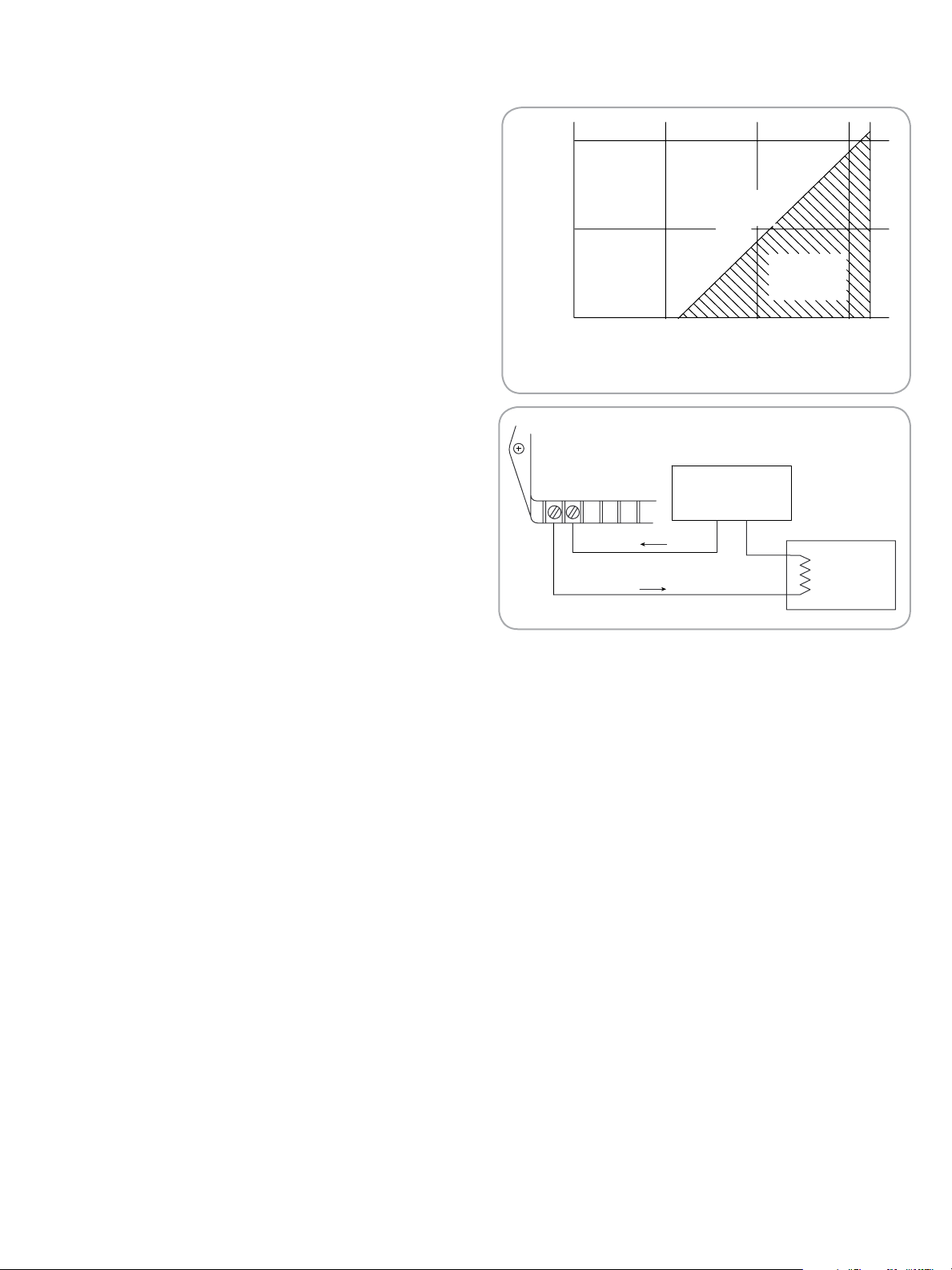
* Loop resistance=Wire res. + Receiver res.
Loop resistance (Ohms)*
0
0102030
500
1000
Maximum resistance
Operating
region
- +
+
-
Receiver
0 to 1050 Ohms
Power Supply
11 to 32 Vac
Wire
Wire
+
-
Two Wire / 4 to 20 mA Output
Electrical
• Supply Voltage: 11 to 32 VDC
(See diagram right for maximum loop resistance)
• Protected against reversal of polarity
• Output limited to approx. 3.85 mA at low end of
span and approx. 25 mA at upper end of span
Ordering Information
Order Number (See Table below and Reference
Table A)
T30 - PPP - O
Example: T30 - 06E - B
PPP= ressure Range O=Offset
(See Note)
See Reference Table A 0=No offset
A=1/4 offset
B=1/2 offset
If the measured differential pressure is expected to
go from positive to negative, a transmitter with offset
(elevated zero) should be ordered.
Three options are available:
“0” No offset. At zero differential pressure, the
output signal is:
4 mA (4 to 20 mA range)
Pressure excursion: 0% to 100% of Range,
see Table A.
“A” 1/4 span offset. At zero differential pressure,
the output signal is:
8 mA (4 to 20 mA range)
Pressure excursion: -33% to 100% of
Range, see Table A.
“B” 1/2 span offset. At zero differential pressure,
the output signal is:
12 mA (4 to 20 mA range)
Pressure excursion: -100% to 100% of
Range see Table A.
To order: Determine the positive pressure range;
from Table A, find the corresponding pressure code.
Then add the required offset (none, A, or B).
For example, T30 05E A is a transmitter with a
maximum range of 1 in (25.40 mm) of H
O at 20 mA
2
and a minimum range of -0.33 in of H2O at 4 mA.
5
Page 6

Amphenol
Advanced Sensors
Table A - Standard Pressure Ranges
English Metric Units
Pressure
Code
03E* 0 to 0.300 in H
04E 0 to 0.500 in H
05E 0 to 1.00 in H
06E 0 to 2.00 in H
07E 0 to 3.00 in H
08E 0 to 5.00 in H
09E 0 to 10.0 in H
*T30 Only
Pressure
Range
English
Maximum
Safe
Momentary
Overpressure
0 03P 0 to 75.0 Pa 03M 0 to 7.50 mm H20
2
0 04P 0 to 100.0 Pa 04M 0 to 10.00 mm H20
2
0 05P 0 to 250 Pa 05M 0 to 25.0 mm H20
2
0 20 in H20 06P 0 to 500 Pa 5 kPa 06M 0 to 50.0 mm H20 500 mm
2
0 07P 0 to 750 Pa 07M 0 to 75.0 mm H20
2
0 08P 0 to 1.00 kPa 08M 0 to 100 mm H20
2
0 5 psid 09P 0 to 2.50 kPa 35 kPa 09M 0 to 250 mm H20 3.5 m
2
Pressure
Code
Pressure
Range
Pascals
Maximum
Safe
Momentary
Overpressure
Pressure
Range
Code
Pressure
Safe Momentary
Pascals
Maximum
Overpressure
www.amphenol-sensors.com
© 2018 Amphenol Corporation. All Rights Reserved. Specications are subject to change without notice.
Other company names and product names used in this document are the registered trademarks or
trademarks of their respective owners.
AAS-920-362E - 07/2018
 Loading...