

Moduline systems DMC-B Operation Manual
Reliable liquid dispensing
at an affordable price
i
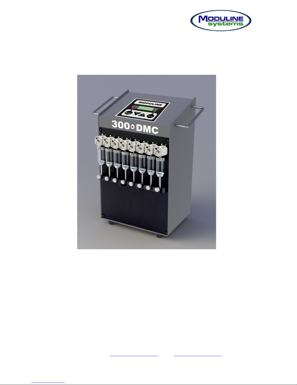
DMC-B (Digital Multi-Channel) Liquid Dispenser
Operation Manual
12513 Loma Rica Drive, Grass Valley, CA 95945
Phone: (530) 272-8786 / Fax: (530) 272-1638
Email: info@modulinesystems.com / Web: www.modulinesystems.com
Moduline Systems/Manuals/Model 300 DMC Digital/Revised 2-11-13

Reliable liquid dispensing
at an affordable price
ii
TABLE OF CONTENTS
Contents Page
Introduction 1
- DMC-B Introduction
- Unpacking
- General System Information
Equipment Setup & Operation 2
- Dispenser Setup
- Dispenser Operation
- Conveyor Setup
- Conveyor Settings
- Using the System
Maintenance 5
- Cleaning and Maintenance
- Syringe Service Procedure
- Syringe Replacement
- Valve Replacement
DMC-B Specifications 10
Figures
# 1 DMC-B Back Panel 11
# 2 DMC-B Display and Controls 12
# 3 Inlet Manifold Installation 13
# 4 Typical Dispenser Conveyor Configuration 14
# 5 Conveyor Off Track Installation 15
# 6 Conveyor Back Panel 15
# 7 Dispense Head Holder Installation 16
# 8 Dispense Head Holder Alignment 17

Reliable liquid dispensing
at an affordable price
1
INTRODUCTION
The DMC-B (Digital Multi-Channel) is a liquid dispenser designed for stand-alone
operation or in conjunction with Moduline Systems conveyors or vial filling platforms. It
is ideal for pre-production process validation, yet capable of performing well in a low to
medium duty production environment.
This manual contains all of the basic information a user needs to set up and operate the
DMC-B.
UNPACKING
The Moduline Systems DMC-B Dispenser is shipped in a specialized container. Open
box carefully and retain all material in the event of component reshipment. Review the
packing list and verify that all items were received.
Standard Contents:
- DMC-B Dispenser
- Power cord
- Inlet tubing – standard inlet tubing is 0.066” ID x 0.090” and is designated by
yellow strain relief on the end that screws into the dispenser’s rotary shear
valves.
- Outlet tubing – standard outlet tubing is (0.045” ID x 0.071” and is designated by
red strain relief on the end that screws into the dispenser’s rotary valve
- 8 needle dispense head
- Inlet Kit
- Inlet Manifold
Accessories and Optional Items
- Syringe (1.0, 2.5, or 5.0 mL)
- Hand or foot switch
- Dispenser interconnect cable (required for dual dispenser configuration)
- Custom dispense head and manifold configurations
- Spare chips – Processor, Eprom
- Conveyor communication/power cable

Reliable liquid dispensing
at an affordable price
2
GENERAL SYSTEM INFORMATION
1. Power must be off when changing syringes or valves to prevent possible injury in the
advent of accidental triggering.
2. When positioning the inlet and outlet fluid lines avoid any sharp bending that may
cause kinking.
3. Take care when installing the threaded line retainer fittings to the valve ports to
prevent cross threading and possible damage to the valve. Fittings should be firmly
finger tightened only.
4. Do not attempt to internally service the rotary shear valves. Any indication of
disassembly will void the warranty.
5. Handle syringes with care. Do not run syringes dry for more than a couple of cycles.
Doing so can cause accelerated wear of plungers.
6. Use the inlet filter system at all times. Clean at regular intervals.
7. For best results clean and rinse the entire system after each use as described in the
maintenance section.
8. The program memory is nonvolatile and will retain data in power off or power failure
conditions.
DISPENSER SETUP
Refer to figures 1 – 3 for visual assistance with the following instructions.
1. Connect power cord to rear of dispenser
2. Power up dispenser. The On switch is located in the rear of the dispenser on the
lower right.
3. Park the dispenser’s drive arm by pressing the [Mode] key once to access
dispenser’s Prime function. Then press [+ / Start] key. Turn off the power when the
dispenser’s drive arm is at or near the bottom of its stroke.
4. Install the syringe – See steps 4-6 of “Syringe Replacement” on page 8
5. Install inlet manifold – Remove the bottom screws from valves 4 & 6 and replace
with standoffs. Remove the thumbscrews from the ends of the standoffs and mount
the inlet manifold. Replace the thumbscrews – finger tight.

Reliable liquid dispensing
at an affordable price
3
6. Connect inlet tubing to inlet port located in the face of the rotary shear valves. The
default inlet tubing has an ID of 0.066” and is indicated by yellow strain relief.
7. Connect outlet tubing to the ports located on top of the of rotary shear valves.
Connect other end to the dispense head, if not already done. The default outlet
tubing has an ID of 0.045” and is indicated by red strain relief.
8. Connect the inlet kit to the bottom of the inlet manifold.
DISPENSER OPERATION
Refer to figure 1-2 for visual assistance with the following instructions.
1. Turn on the dispenser
2. Set Syringe Size – Press the [Select] key until the arrow on the left side of the
display points to Syringe. Press the [Stop / -] or [+ / Start] key until the desired size
is displayed (standard sizes – 1.0, 2.5, or 5.0 mL).
3. Set Dispense Volume – Press the [Select] key until the arrow in the display points to
Volume (default position). Press the [Stop / -] or [+ / Start] key until the desired
volume is displayed. See specification section for available range for each syringe
size.
4. Set Dispense Speed – Press the Select key until the arrow on the left side of the
display points to Disp SPD. Press the [Stop / -] or [+ / Start] key until the desired
speed is displayed (range is 1 – 10).
5. Set Fill Speed – Press the [Select] key until the arrow in the display points to the Fill
SPD. Press the [Stop / -] or [+ / Start] key until the desired speed is displayed
(range is 1 – 10).
6. Insert the inlet side of inlet tube into fluid reservoir and the dispense head of the
outlet tube into an appropriate catch container.
7. Prime syringe - Press the [Mode] key once to access dispenser’s Prime function.
Press [+ / Start] key. When you are satisfied that the syringe is sufficiently primed
(minimal bubbles in the syringe and tubing), press the [- / Stop] key.
8. System shutdown - Press the [Mode] key two times to select the Empty function.
Press [+ / Start] key to activate the return of system fluid to the reservoir. The
dispenser will cycle through the emptying process twice then stop automatically.
Repeat the process until the syringe and tubing are sufficiently empty of fluid.

Reliable liquid dispensing
at an affordable price
4
CONVEYOR SETUP
Refer to Figures 1, 4 - 7 for visual assistance with the following instructions.
1. Set the conveyor and DMC-B on a suitable table or workbench arranged with the
DMC-B behind the conveyor. See Figure 4.
2. Join the off track to the handle grip on the left hand side of the conveyor using the
screws provided in the handle. See Figure 5.
3. Connect the gray phone type communication cable by inserting the ends into the
rear mounted communication receptacles on the conveyor and the dispenser. See
Figures 1 & 6. NOTE: The plug’s release key tab must be properly mated with the
socket’s key slot for proper seating. A fully engaged plug is locked into the socket
and can be removed only by depressing its key tab.
4. Install the dispense head holder onto the conveyor noting the alignment with the
positioning arrow. See Figure 7.
5. Mount the dispense head onto the holder’s cross piece by guiding the two mounting
thumbscrews into the slot and pushing fully inward until contact is made with the
holders upright. Tighten screws. Thumbscrew heads must be on the right side of
the cross piece.
CONVEYOR SETTINGS
1. Column Format Switch is located on the back of the conveyor to the right of the
communication cord socket. This control sets the number of times the conveyor will
stop per plate. Set the switch to 12 for typical DMC-B operations.
Column Format Selector Switch - sets the plate advancement steps.
Set to 3 when using 4 x 8 port manifold (3 dispensing stops per plate)
Set to 6 when utilizing 2 x 8 port manifold (6 dispensing stops per plate)
Set to 12 when utilizing 1 x 8 port manifold or dispense head (12 dispensing stops per plate)
2. Conveyor Belt Speed Dial is located to the right of column format switch on the back
of the conveyor. This control regulates the speed of the plate moving belt.
3. Conveyor Start / Stop Button is located on the front of the conveyor under the red
power indicator. This control starts and stops all dispensing programs.
 Loading...