

Page 1
Reliable liquid dispensing
at an affordable price
Model A Dispenser
Operation Manual
Moduline Systems\Manuals\Model A Ver 2/20/13
12513 Loma Rica Dr., Grass Valley, CA 95945
Phone: (530) 272-8786 / Fax: (530) 272-1638
Email: [email protected]
Web: www.modulinesystems.com
Page 2

Reliable liquid dispensing
at an affordable price
Table of Contents
Contents Page
Introduction 1
Initial Setup – Installing & Adjusting Syringe 1
Final Setup for Use as a Handheld Dispenser 1
Final Setup for Use as an Automated Dispenser 2
Using the System 2
Clean Up 2
Figures
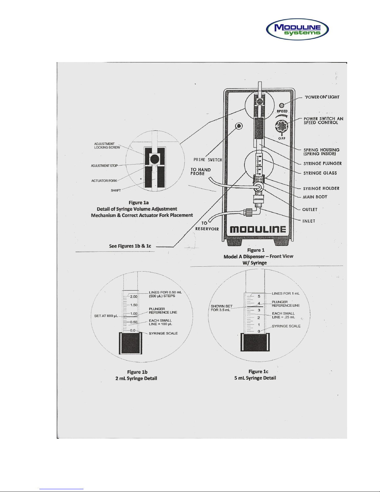
(1) Model A Dispenser – Front View with Syringe Installed 4
a. Detail of Syringe Adjustment Mechanism &
Placement of Actuator Fork
b. Detail View of 2 mL Syringe
c. Detail View of 5 mL Syringe
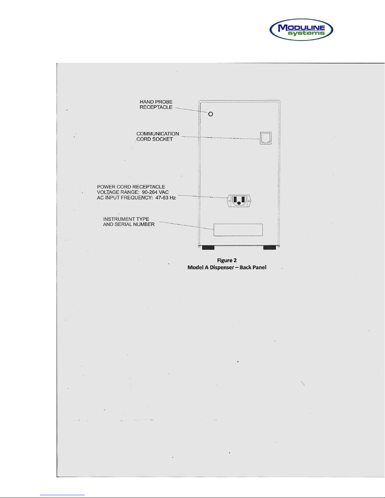
(2) Model A Dispenser – Back Panel 5
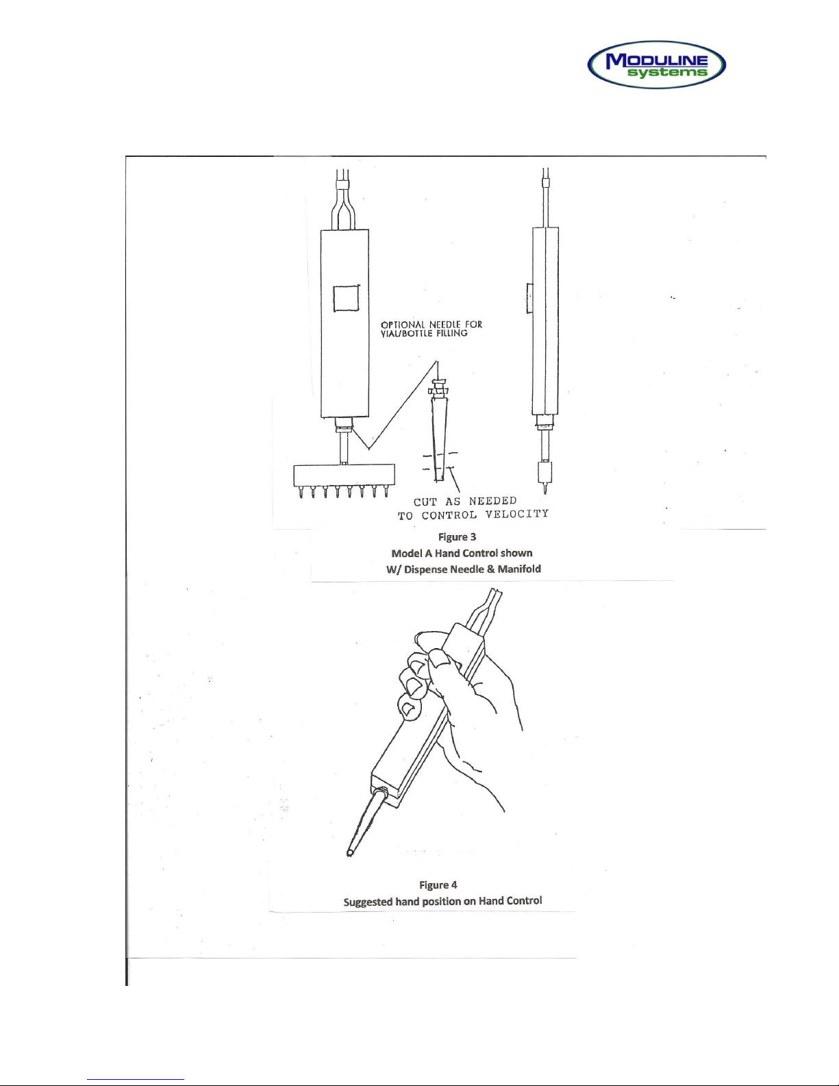
(3) Model A Hand Control with Dispense Manifold & Needle 6
(4) Suggested Hand Position on Hand Control 6
Specifications 7
i
Page 3

Reliable liquid dispensing
at an affordable price
Introduction
The Moduline Systems Model A Dispenser is an analog syringe pump designed for
precision hand and automated microplate dispensing.
The Model A will be shipped in 1 – 2 boxes depending on what accessories are ordered
with it. Open boxes carefully and retain all materials in the event of a component return or
subsequent shipment to an alternate location.
Initial Setup – Installing and Adjusting Syringe Volume
Safety Note: Always turn the power off when installing, removing, or adjusting the syringe to
prevent accidental actuation and possible harm to finger or syringe.
1. Install the syringe assembly to the front panel by first guiding the metal plunger shaft into the
slot of the actuator fork (NOTE: adjustment stop must be on the top side of actuator fork as
shown in figure 1a) and then pressing the syringe main body fully into the black syringe
holder receptacle. It is important that the syringe be grasped by the main body when being
installed or removed. Failure to do so will put excess stress on the plastic extremities and
lead to premature part failure.
2. Determine the required syringe volume setting. For single needle dispensing the volume
setting is simply the desired volume. When a manifold is to be used the volume setting is the
total of all of the well volumes being filled. Example:
Desired 100 µL per well
8 port manifold used
8 x 100 µL = 800 µL
Figure 1b shows a 2 mL syringe set at 800 µL
3. Loosen the adjustment locking screw.
4. Raise the plunger shaft upward until the plunger reference line is aligned with the desired
volume on the syringe scale – See Figures 1b & 1c.
5. With the adjustment stop resting on top of the actuator fork, firmly re-tighten the adjustment
locking screw.
6. Install the AC Power cord into the dispenser’s rear panel mounted receptacle – See Figure
2. The internal power system is automatically compatible within the voltages range of 90 –
264 VAC @ 47 to 63 Hz.
Final Setup for Use as a Handheld Dispenser
1. Insert the dispenser control plug of the hand held dispense controller into the dispense
control receptacle – See Figure 2.
1
Page 4

Reliable liquid dispensing
at an affordable price
2. Connect the Inlet fluid line to the syringe’s inlet (bottom) port.
3. Connect the fluid inlet line of the hand control to the syringe’s outlet (top) port.
4. For single vial or tube filling, install the luer mounted plastic tip to the mated fitting of the
hand control. For microplate filling, attach the 8 port manifold to the luer fitting on the
hand control as shown in Figure 3
Final Setup for Use as an Automated Dispenser
IMPORTANT: POWER MUST BE REMOVED (OFF) FROM THE DISPENSER UNIT WHEN
INSTALLING OR REMOVING THE COMMUNICATION CABLE. FAILURE TO DO SO MAY
DAMAGE ELECTRONIC COMPONENTS.
1. Connect one end of the communication cable to the rear of the Model A and the other to
the rear of the conveyor.
2. Connect the inlet fluid line to the syringe’s inlet (bottom) port.
3. Connect the inlet fluid line of the dispense manifold to the syringe’s outlet (top) port
Using the System
See conveyor manual for use as an automated dispenser
1. Insert inlet line into the reagent reservoir.
2. Adjust the dispenser’s speed control for the fastest speed possible that does not cause
splashing. Avoid low speeds when using a manifold as this will cause the precision to be
lower.
3. Normally, the hand control is held in the palm and activated with the thumb as shown in
Figure 4.
4. With all components connected, place the dispense manifold / needle over a catch
receptacle and hold down the push button on the hand control, or alternately move the
prime switch on the Model A to the “Up” position, until bubble free fluid is being
dispensed from the manifold / needle.
Note: A single press of the push button will produce 1 dispense. Held down, the dispensing
will be continuous at a rate set by the speed control, until released.
5. Best results with microplate dispensers will be achieved by holding the hand control as
shown in Figure 4 with the fluid being directed against the side wells.
6. If a manifold needle becomes clogged, insert the cleaning wire into its bore to remove
the obstruction as shown in instructions that accompany the manifold.
System Cleanup
1. Remove the Teflon reagent pickup straw from the reservoir.
2. Place the dispense manifold / needle over a suitable container.
2
Page 5

Reliable liquid dispensing
at an affordable price
3. Hold down the hand control dispense button or initiate a prime cycle by moving the prime
switch to the down position until all reagent has been removed from the system.
4. After the system is empty, it should be flushed with an appropriate cleaning solution, if
desired, and finally with distilled water. This is done by placing the Teflon reagent pickup
straw into the liquid and again priming until the system is completely rinsed of the reagent.
It is recommended that the system be left “wet” until the next use. If possible the
manifold should have its needles submerged in water to prevent drying out and
possible clogging.
3
Page 6
Reliable liquid dispensing
at an affordable price
4
Page 7
Reliable liquid dispensing
at an affordable price
5
Page 8
Reliable liquid dispensing
at an affordable price
6
Page 9

Reliable liquid dispensing
at an affordable price
Model A – Specifications
Pump Type
Positive displacement single-channel syringe pump
Precision
CV Syringe manifold Configuration
≤ 3% 2 mL syringe with 8 Port Manifold
Operating Parameters
Standard Syringe sizes 2.0 mL 5.0 mL
Resolution 100 µL 250 µL
Range 100 µL to 2000 µL 250 µL to 5000 µL
Power Requirement
100 – 240 VAC 0.5A 50 – 60 Hz
Fluid Contact Materials
Syringe: Borosilicate glass and PTFE seal (UHMWPE optional), connecting parts
consist of ABS, Delrin & HDPE
Valves: Polypropylene body & EPDM O-Ring
Filter: Acetal w/Delrin washer
Dimensions
Height 9 3/8 in. (238 mm)
Width 4 1/4 in. (106 mm)
Depth 6 1/2 in. (165 mm)
Weight 4 3/4 Lb (2.15 kg)
Environmental (Operating)
Temperature 15 C to 40 C (59 F to 104 F)
Humidity 20% to 95% RH at 40 C (104 F)
Throughput with Moduline Systems Conveyor
Plates / Hr Dispenser Configuration
180 1 Model A with 8 port manifold
280 1 Model A with 16 port manifold
340 2 Model A dispensers with 8 port manifolds
480 2 Model A dispensers with 16 port manifolds
Regulatory Compliance
The Model A is a general laboratory device not subject to FDA regulatory approval.
UL / CE approved components are used wherever possible.
7
 Loading...