

Modular 110/90 PCE, 90/120 CFE, 110/90 CFES, 90/80 CFE, 90/80 CFES Operating Instructions Manual
...
Code 252.102.12
~
http://torgoborud.com.ua/Plity-elektricheskie-promyshlennye.html
~
¸
ELECTRIC RANGES / ELECTRIC OVEN
SERIES "65"; "7"; "9"; “LD”
Mod. 65/40 PCE 65/70 PCE 65/70 CFE
70/40 PCE 70/70 PCE 70/70 CFE
70/40 PCE -T 70/0 PCE-T
70/40 PCEQ 70/70 PCEQ 70/70 CFEQ
70-40 PCEQ-T 70-70 PCEQ-T 70-110 PCEQ-T
90/40 PCE 90/80 PCE 90/120 PCE
90/80 CFE 90/120 CFE 70/110 PCEQ
90/80 CFES 90/120 CFES 70/110 CFEQ
110/50 PCE 110/90 PCE 110/90 CFES

INDEX
Paragraph Installation instructions
1 Compliance with EEC directives
1.1 Installation drawings
1.2 Wiring diagrams
1.3 Electrical specifications
1.4 Technical data
2 Preliminary installation instructions
2.1 Regulations, technical rules and general specifications
2.2 Installation
2.2.1 Electrical connection
2.2.1.1 Equipotential connection
2.3 Safety devices
Paragraph User instructions
3 Start-up
3.1 Operating Instructions - Start-up and switching-off
3.2 Starting-up the convection oven
3.3 Starting-up the electric static oven
4 Maintenance, cleaning and care
4.1 Information about electricity and its use
4.2 Correct treatment of the cooking plates
INSTALLATION INSTRUCTIONS
1. CONFORMITY WITH EEC DIRECTIVES
REMARK: The electric ranges are made in compliance with the basic requirements envisaged by
EEC directives, in accordance with “EEC Directive 73/23 on low voltage”, “EEC Directive 89/336
on electromagnetic compatibility” and are marked “CE” according to the EEC Directive 93/68.
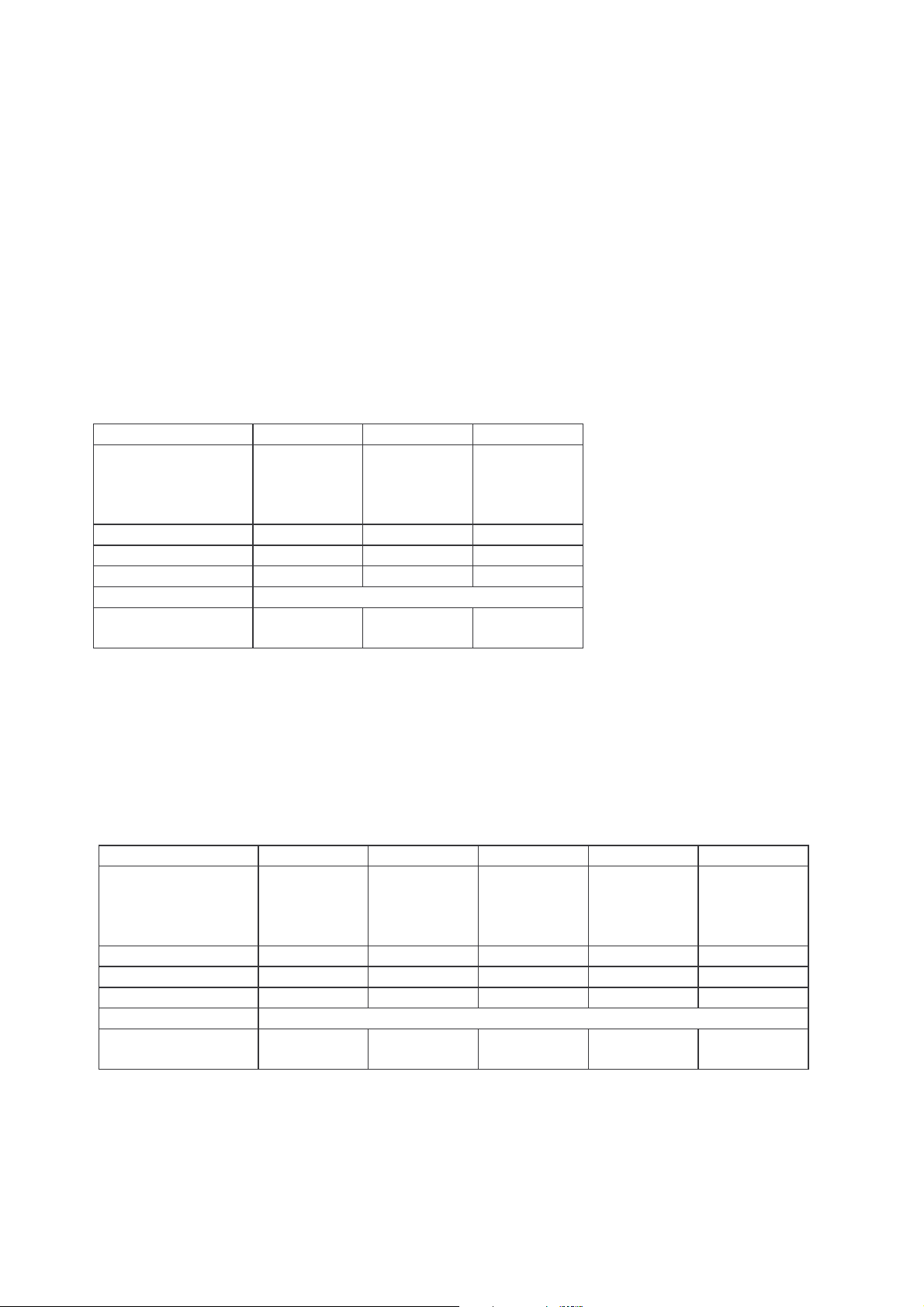
1.3 ELECTRICAL SPECIFICATIONS:
Model
Dimensions mm
Width
Depth
Height
El. plates - kW
El. oven kW
Total power kW
Rated voltage
Power cable
Cross section
65/40 PCE 65/70 PCE 65/70 CFE
400
650
300 (400)
700
650
300 (400)
700
650
850 (950)
2 x 2,4 4 x 2,4 4 x 2,4
/ / 3,96
4,8 9,6 13,56
400V-3N ~ 50 Hz
HO5RN-F
5 x 1.5 mm
HO5RN-F
2
5 x 2.5 mm
HO5RN-F
2
5 x 4 mm2
The data plate shows all the necessary data for the installation and can be found on the terminal
block cover on the rear of the left-hand side panel in the model 65/70 CFE and on the rear panel
in the models 65/40 PCE and 65/70 PCE.
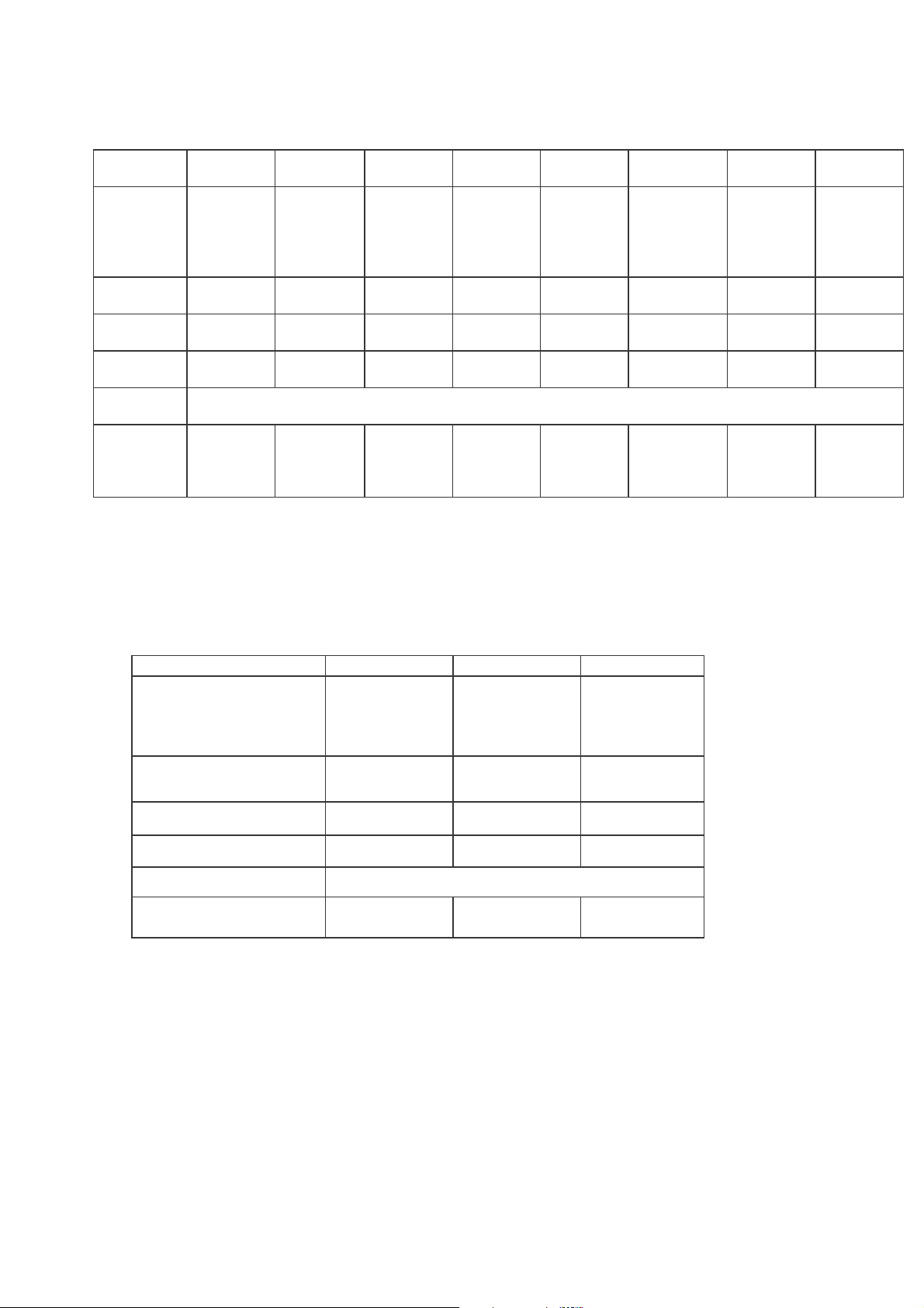
Model
Dimensions mm
Width
Depth
Height
El. plates - kW
El. oven kW
Total power kW
Rated voltage
Power cable
Cross section
70/40 PCE 70/70 PCE 70/70 CFE 70-40 PCE-T 70-70 PCE-T
400
700
850 (980)
700
700
850 (980)
700
700
850 (980)
400
700
280 (430)
700
700
280 (430)
2 x 2,4 4 x 2,4 4 x 2,4 2 x 2,4 4 x 2,4
/ / 3,96 / /
4,8 9,6 13,56 4,8 9,6
400V-3N ~ 50 Hz
HO5RN-F
5 x 1.5 mm
HO5RN-F
2
5 x 2.5 mm
HO5RN-F
2
5 x 4 mm2
HO5RN-F
5 x 1.5 mm
HO5RN-F
2
5 x 2.5 mm
2
The data plate contains all necessary information with installation and it is located on the left side
of the unit,near the terminal block on models
70/40 PCE; 70/70 PCE; 70-40 PCE-T; 70-70 PCE-T and
on the terminal block cover on the rear of the left-hand side panel in the model 70/70 CFE.
Model
Dimension
mm ù
Width
Depth
Height
El. plates
kW
El. Oven
kW
Total
power kW
Rated
voltage
Power
cable
Cross
section
70/40
PCEQ
400
700
850 (980)
2 x 2,6 4 x 2,6 6 x 2,6 2 x 2,6 4 x 2,6 6 x 2,6 4 x 2,6 6 x 2,6
/ / / / / / 3,96 3,96
5,2 10,4 15,6 5,2 10,4 15,6 14,36 19,56
HO5RN-F
5 x
1.5mm2
70/70
PCEQ
700
700
850 (980)
HO5RN-F
5 x 2.5
mm2
70/110
PCEQ
1100
700
850 (980)
HO5RN-F
5 x 2.5
mm2
70 -40
PCEQ-T
400
700
280 (430)
400V – 3N ~ 50 Hz
HO5RN-F
5 x
1.5mm2
70-70
PCEQ-T
280 (430)
HO5RN-F
5 x 2.5
700
700
mm2
70-110
PCEQ-T
1100
700
280 (430)
HO5RN-F
5 x 2.5 mm
70/70
CFEQ
850 (980)
HO5RN-F
2
5 x 4 mm2
700
700
850 (980)
HO5RN-F
5 x 4 mm2
The data plate shows all necessary data for installation and and can be found on the terminal
block cover, inside the compartment, in the models 70/40 PCEQ; 70/70 PCEQ; 70/110 PCEQ
and on the terminal block cover on the rear of the left-hand side panel in the models 70/70 CFEQ
e 70/110 CFEQ.
Model
Dimensions mm
Width
Depth
Height
El. plates kW
90/40 PCE 90/80 PCE 90/120 PCE
400
900
850 (1000)
1 x 3
1 x 4
800
900
850 (1000)
3 x 3
1 x 4
1200
900
850 (1000)
4 x 3
2 x 4
70/110
CFEQ
1100
700
El. oven kW
Total power kW
Rated voltage
Power cable
Cross section
/ / /
7 13 20
400V - 3N ~ 50 Hz
HO5RN-F
5 x 2.5mm2
HO5RN-F
5 x 4 mm2
HO5RN-F
5 x 4 mm2
The data plate shows all necessary data for installation and can be found on the terminal block
cover, inside the compartment.

Model
Dimensions mm
Width
Depth
Height
El. plates kW
El. oven kW
Total power kW
Rated voltage
Power cable
Cross section
90/80 CFE 90/120 CFE 90/80 CFES 90/120 CFES
800
900
850 (1000)
3 x 3
1 x 4
1200
900
850 (1000)
4 x 3
2 x 4
800
900
850 (1000)
3 x 3
1 x 4
1200
900
850 (1000)
4 x 3
2 x 4
3,96 3,96 6 6
16,96 23,96 19 26
400V - 3N ~ 50 Hz
HO5RN-F
5 x 4 mm2
HO5RN-F
5 x 6 mm2
HO5RN-F
5 x 6 mm2
HO5RN-F
5 x 6 mm2
The data plate shows all necessary data for installation and can be found on the terminal block
cover on the rear of the left-hand side panel.
Model
Dimensions mm
Width
Depth
Height
El. plates kW
110/50 PCE 110/90 PCE 110/90 CFES
500
1100
850 (1000)
1 x 3
1 x 4
900
1100
850 (1000)
3 x 3
1 x 4
900
1100
850 (1000)
3 x 3
1 x 4
El. oven kW
Total power kW
Rated voltage
Power cable
Cross section
/ / 9
7 13 22
400V - 3N ~ 50 Hz
HO5RN-F
5 x 2.5mm2
HO5RN-F
5 x 4 mm2
HO5RN-F
5 x 6 mm2
The data plate shows all necessary data for installation and can be found on the terminal block
cover, inside the compartment on the models 110/50 PCE, 110/90 PCE and on the right side of
the model 110/90 CFES.

2. PRELIMINARY INSTALLATION INSTRUCTIONS
The appliance must be positioned in a well-aired room, if possible under a hood to remove
cooking steam thoroughly.
Before starting the appliance, remove all protective film; thoroughly clean the surfaces with a soft
cloth, lukewarm water and detergent, so as to remove all anti-rust products applied during the
manufacturing stage, then dry with a clean cloth.
If the appliance is installed near walls, partition walls, kitchen furniture, decorative panelling, etc.,
these should be constructed with fireproof materials or a space of at least 100 mm should be left
free.
Make sure that fire prevention rules are strictly respected.
The appliances can be positioned - according to the models - as top or ground appliances, or
linked together with others of the series.
The main switch and the socket must be near the appliance and easily accessible.
Using the levelling feet lay the appliance flat, adjust the height and ensure its stability.
2.1 Regulations, technical rules and general specifications
Comply with the following rules during assembly:
1) accident prevention rules;
2) rules in force in the country where the appliance is installed;
3) carefully read this booklet as it contains important instructions about installation safety, use
and maintenance;
4) keep this booklet for further reference.
2.2 Installation
Installation, setting up and maintenance must be carried out by qualified personnel only.
Installation must be carried out in accordance with the rules in force in the country where the
appliance is installed.
The manufacturer declines all responsibility for incorrect functioning resulting from defective
installation, tampering, improper use, bad maintenance, non-observance of the local rules and
use by unskilled persons.
INSTALLATION INSTRUCTIONS
APPLIANCE WITH WEIGHT GREATER THAN 40 Kg
BEFORE POSITIONING THE APPLIANCE CONNECT THE POWER CABLE TO THE
TERMINAL BLOCK.

2.2.1 Electrical connection
1) The electric ranges are designed to operate off 400 VAC+3N voltage.
2) The connection to the mains must be carried out through a suitably rated trip switch which has
at least 3 mm between the contacts. Moreover, the mains voltage - when the appliance is
working - must not exceed ± 10% of the voltage value.
3) The power cable to connect the appliance to the mains must be at least equal to the H05RN-F
rubber insulated type, with cross section suitable to the max. power consumption; therefore, its
lowest cross section must comply to the data stated in the electrical specifications table for
each type of appliance.
4) On top appliances the cable inlet and the terminal block are on the rear side. To carry out the
connection, unscrew and remove the protective cover.
To gain access to the terminal block on ground appliances with an oven, the protective cover
on the left-hand side of the appliance must be removed; on the ranges with a cabinet
underneath the protective cover of the terminal block on the inner left-hand side of the cabinet
has to be removed; to carry out the connection, insert the cable through the inlet gland and the
cable-clamp and connect the wires to the relative binding posts.
5) The appliance must be provided with an efficient earth connection.
For this purpose, near the terminal block there is a binding post marked with the symbol
to which the earth wire (yellow-green) must to be connected.
The above-mentioned cable must be long enough so that – if the cable clamp loosens - it can
be stressed only after the feed wires have been disconnected .
NB: Earthing must be carried out according to the local standards and regulations in force.
2.2.1.1 Equipotential connection
When interconnecting multiple appliances together, the electric range must be included in an
equipotential system, whose efficiency has to be checked according to the rules in force. The
connection is on the rear panel in top appliances, and on the left-hand side of the bottom frame in
ground appliances, marked with “EQUIPOTENTIAL”.
Earth wires for appliances
Terminali cavetti di terra apparecchiatura
NB: The manufacturer declines all responsibility for damage resulting from noncompliance with accident prevention rules as described above.

2.3 AVAILABLE SAFETY DEVICES
In addition to the thermostat the appliance is equipped with a temperature limit switch, which
switches off the oven in case of failure by the main thermostat. When failure occurs, contact the
after sales service.
The hot plates are also fitted with a thermal cutout which automatically switches off the power
supply, thus preventing overheating of the heating element and consequently operating danger.

USER OPERATING INSTRUCTIONS
3 PUTTING INTO OPERATION
Ranges are appliances designed for cooking food and should be exclusively used by trained
personnel following these operating instructions. Any other use of the appliance is to be
considered improper and therefore dangerous.
3.1 OPERATING INSTRUCTIONS, SWITCHING ON AND SWITCHING OFF
Each hot plate can be turned through six positions. Turn the hot plate selector switch from "0" to
the desired position (pilot lamp on). The green pilot lamp indicates that the appliance is on. Turn
the hot plate selector switch to position "0" to switch off.
Above the selector switch there is a symbol which indicates the cooking position of the plate.
When you switch on, the plate corresponding to the symbol will be heated.
3.2 OPERATING INSTRUCTIONS: CONVECTION OVEN
Turn the main switch on. Turn the thermostat knob from "0" to the desired position between 50°C
and 300°C (both pilot lamps lit). The green pilot lamp indicates that the appliance is on, the yellow
pilot lamp indicates that the heating element of the ventilated oven is functioning. As soon as the
desired temperature has been reached, the yellow pilot lamp switches off. Turn the thermostat to
the "0" position to switch off the oven. The oven is heated by forced air.
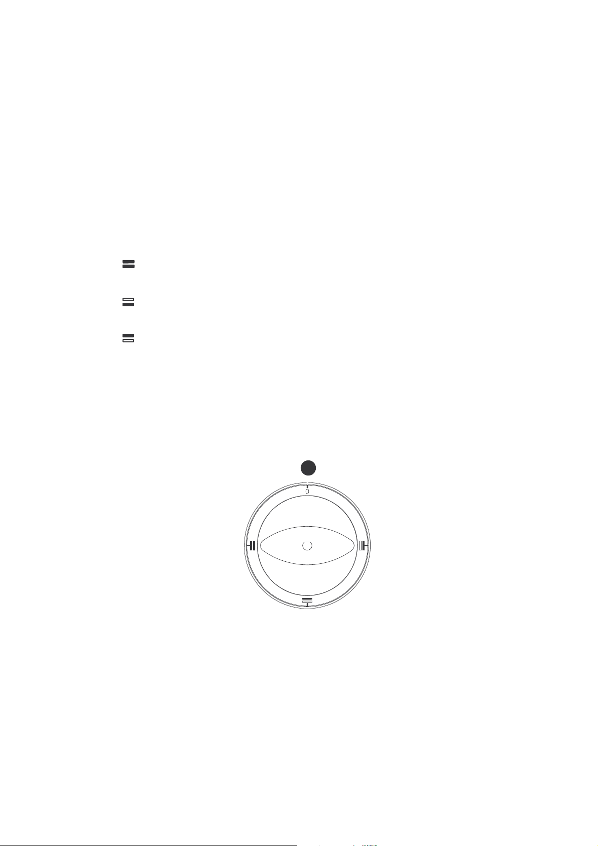
3.3 OPERATING INSTRUCTIONS: ELECTRIC STATIC OVEN
By turning the knob scaled from 0 to 300 °C clockwise the main switch switches on, the green
pilot lamp indicates that the appliance is on and the desired temperature - from 50 °C to 300 °C
can be set by means of the thermostat.
By turning the knob with the stroke symbols (upper and lower heating elements) clockwise the
following functions can be set:
a) Position "0": = oven and yellow pilot lamps turned off.
b) Position = total/complete heating of the oven by means of the upper and lower heating
elements, the two yellow pilot lamps are turned on.
c) Position = Only the lower part of the oven is heated and the lower yellow pilot lamp is
turned on.
d) Position = Only the upper part of the oven is heated and the upper yellow pilot lamp is
turned on.
As soon as the set temperature has been reached the yellow pilot lamps turn off and turn on
again in cycles on how the oven is cooking.
The oven is heated by static air.

4 MAINTENANCE, CLEANING AND CARE
ATTENTION: Do not wash the appliance with direct water jets or with a high-pressure
cleaner!
Before carrying out any cleaning operations disconnect the power at the mains.
The hot plates must be allowed to cool before they can be cleaned.
The steel parts must be cleaned using a smooth cloth, water and common detergents. The
detergents must not contain corrosive or abrasive substances as they could damage the steel
surface. After cleaning rinse well and dry thoroughly.
Before a long period of inactivity:
Disconnect the power at the mains. Clean the appliance thoroughly and dry well.
What to do in case of failure:
Turn off the appliance and contact the after sales service.
Maintenance
Maintenance has to be exclusively carried out by trained personnel. Switch off the power before
proceeding with any maintenance operation.
It is recommended that the installation be checked by an authorised technician at least once a
year. We suggest that you undersign a technical assistance contract.
4.1 INFORMATION ABOUT ELECTRICITY AND ITS USE
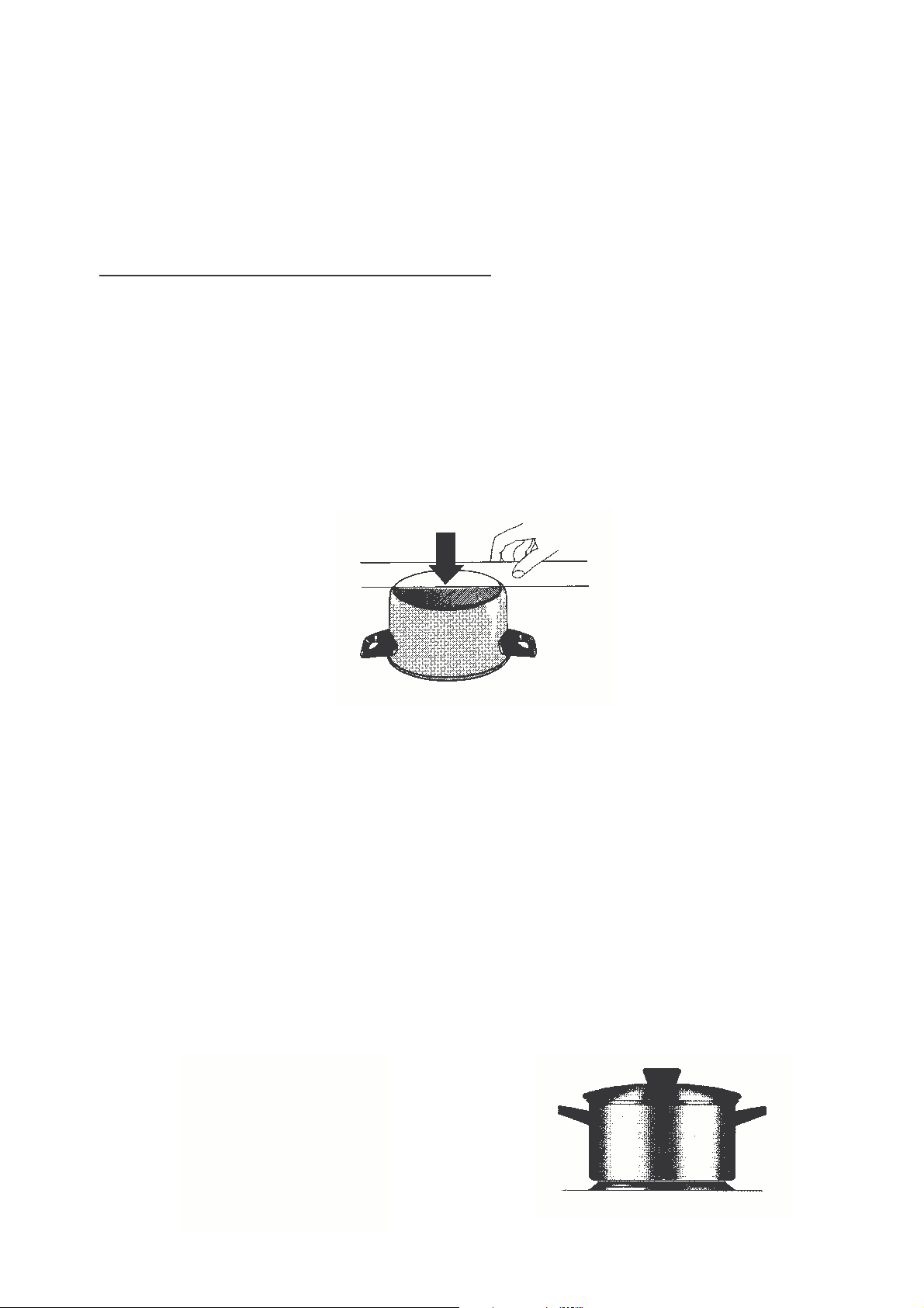
THE USE OF HOT PLATES AND SUITABLE PANS
Use only suitable pans on these hot plates, i.e. pans suitable for cooking on hot plates.
These kinds of pans have a solid bottom with only a slight lower curve, so that the bottom of the
pan is in the widest contact with the hot plate in function. This way heat can be optimally utilised.
In conformity with DIN44904 the maximum interior curve, when the pan is cold, shall not exceed
6% of the bottom’s diameter (including curves which are already present). By using a ruler or on
a perfectly even table, it is easy to verify the pan’s bottom.
Extensively curved pans are not suitable.
Never use pans which are externally curved. If possible buy DIN44904 pans.
Pan bottom permitted
diameter curve
Ø 145 mm 0.8 mm
Ø 180 mm 1.1 mm
Ø 220 mm 1.3 mm
If the pan is too small, energy will be wasted. Food could drop onto the hot plate and burn. This
results in difficult cleaning operations and can cause oxidisation if it is not immediately cleaned.
Use sufficiently large pans. The bottom of the pan must be as big as the hot plate. This way heat
can be utilised in the best possible way and food can not drop onto the plate. You are advised to
use pans with a lid. This way heat is kept within the pan.

http://torgoborud.com.ua
4.2 CORRECT TREATMENT OF THE HOT PLATES
Only dry pans are to be put on the hot plates. Do not place wet objects on them, such as lids.
CARE:
Before using the hot plates for the first time you are advised to leave it on without pans (for 3 - 5
minutes at the highest position for the hot plates with 7 positions; position 5 - 6 for the automatic
plates). This way the protective coating can increase its resistance. Then you are advised to
clean the hot plates with a damp cloth from time to time. Hot plates that are very dirty should be
cleaned with a damp cloth and common detergents.
IMPORTANT:
Each time a hot plate is cleaned it is important to remove the detergent and to dry the hot plate
switching on and heating for a short period.
After cleaning the hot plate you are advised to oil it; this way the hot plate will always keep its
new look.
 Loading...