

Mod-tronic 40T Specifications
Out 1 solidly lit
Out 1 flashing
°C
°F
Loc
Pr1
DWYER INSTRUMENTS, INC.
Phone: 219/879-8000 www.dwyer-inst.com
P.O. BOX 373 • MICHIGAN CITY, INDIANA 46361, U.S.A. Fax: 219/872-9057 e-mail: info@dwyer-inst.com
DWYER INSTRUMENTS, INC.
Phone: 219/879-8000 www.dwyer-inst.com
P.O. BOX 373 • MICHIGAN CITY, INDIANA 46361, U.S.A. Fax: 219/872-9057 e-mail: info@dwyer-inst.com
©Copyright 2009 Dwyer Instruments, Inc. Printed in U.S.A. 12/09 FR# R5-443741-00
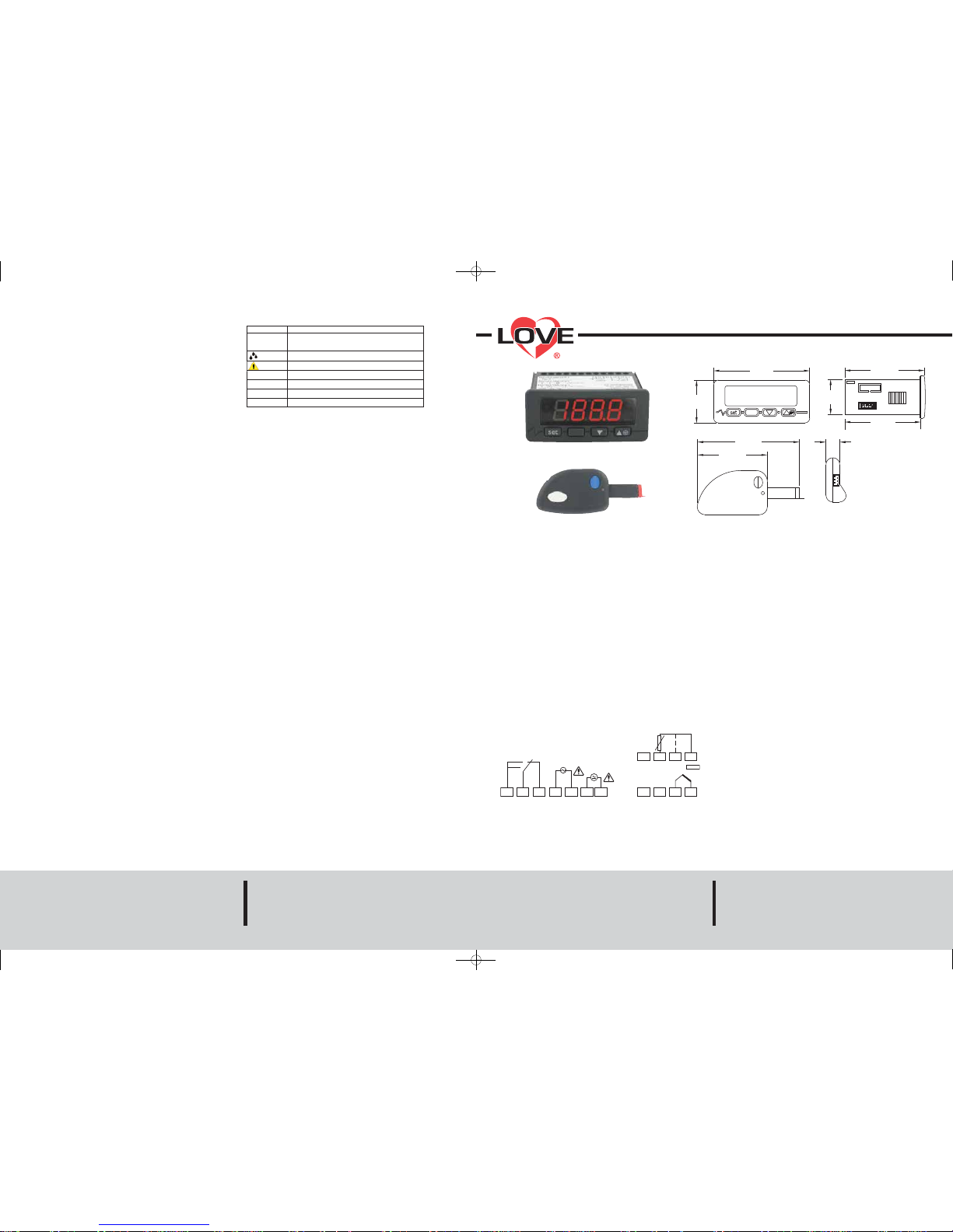
The Series 40T Digital Temperature Switch accepts thermocouple and RTD inputs
to allow temperature measurements and set points up to 1999°F (1300°C). Observing the current status of the control is made easier with the 3-1/2 digit, multi-color LED
display that has alarm, defrost and output symbols. For added versatility, the temperature units can be field selected for °F or °C. For cooling applications, manual defrost
mode can be initiated by pushing a single button. A flashing alarm informs users when
the current temperature exceeds preset limits. When programming multiple units, a
programming key is available to reduce set up time.
INSTALLATION
Note: Unit must be mounted away from vibration, impacts, water and corrosive
gases.
• Cut hole in panel 71 x 29 mm (2.80 x 1.14 in)
• Apply silicone around the perimeter of the hole to prevent leakage
• Insert unit into hole from the front side of the panel
• Slide the mounting bracket securely against the panel from the rear of the
unit
• Wiring diagram is displayed on top of the control
WIRING
Avoid installing the temperature probe cables in close proximity of any power cables.
If the length of the probe cables is longer than 100 meters, a recalibration adjustment
may be made using the CA1 parameter.
Series 40T Digital Thermocouple/RTD Temperature Switch
Specifications - Installation and Operating Instructions
Bulletin T-40T
SPECIFICATIONS
Probe Range: K T/C: -140 to 1999°F (-100 to 1300°C);
J T/C: -140 to 1450°F (-100 to 800°C);
RTD: -320 to 1200°F (-200 to 650°C).
Input: Pt100 RTD and J/K type thermocouple.
Output: 16A @ 250 VAC SPDT relay (max current allowed is 10A).
Control Type: On/off.
Power Requirements: 12 to 24 VAC/VDC, 115 VAC or 230 VAC (depending on
model).
Accuracy: ±1% F.S.
Display: 3-1/2 digit red display.
Resolution: 0.1°C.
Memory Backup: Non-volatile memory.
Temperature Limits: 32 to 131°F (0 to 55°C).
Weight: 2.3 oz (65 g).
Front Panel Rating: IP 65.
Agency Approvals: UL, CE.
DISPLAYING ROOM TEMPERATURE
If the P5 parameter is set to display the temperature set point, the probe temperature
can be displayed by pressing the DOWN ARROW key for two seconds until Pb1 is displayed. Next, hit the SET key. To return to the normal display, press SET key.
MANUAL DEFROST ACTIVATION/DEACTIVATION
To manually activate the defrost cycle, press the UP ARROW key for four seconds.
This feature is disabled during heating operation.
PARAMETER LOCK OUT ACTIVATION/DEACTIVATION
The key pad lock out can be activated/deactivated by pressing the SET and DOWN
ARROW keys simultaneously for two seconds. The display will flash Loc or UnL to signify the change in states.
ALARM BUZZER RESET
The audible alarm can be silenced by pressing any key.
RESTORING FACTORY DEFAULT SETTINGS
Factory settings can be restored by following the below procedure:
• Pressing the UP ARROW and DOWN ARROW keys for four seconds until PA is
displayed
• Press the SET key
• Press the UP ARROW or DOWN ARROW to adjust the value to 743
• Press SET key
• Pressing the UP ARROW and DOWN ARROW keys for four seconds until dEF is
displayed
• Press SET key
• Press the UP ARROW or DOWN ARROW to adjust the value to 149
• Press SET key
• Cycle the power after the flashing dEF goes away
Output 1 is active
Either modification of set point or call for load during
load protection (C1 or C2)
Defrost cycle is active
Alarm condition is present
Temperature is measured in °C
Temperature is measured in °F
Key pad is locked
Probe 1 error
DISPLAY MESSAGES
ADJUSTING PARAMETER VALUES
In order to change the parameter values, follow the procedure below:
• Press UP ARROW and DOWN ARROW simultaneously for four seconds until PA is
displayed
• Press SET
• Use UP ARROW or DOWN ARROW to adjust value to -19
• Press SET
• Press UP ARROW and DOWN ARROW simultaneously for four seconds until SP is
displayed
• Use UP ARROW or DOWN ARROW to cycle through parameters
• Press SET to view value of parameter
• Use UP ARROW or DOWN ARROW to adjust value of parameter
• Press SET to store value
• Press UP ARROW and DOWN ARROW simultaneously for four seconds to exit
menu
MAINTENANCE, CLEANING AND REPAIR
After final installation of the unit no routine maintenance is required. Clean the surface
of the display controller with a soft and damp cloth. Never use abrasive detergents,
petrol, alcohol or solvents. A periodic check of the system calibration is recommended.
The Series 40T is not field serviceable and should be returned if repair is needed (field
repair should not be attempted and may void warranty). Be sure to include a brief description of the problem plus any relevant application notes. Contact customer service to receive a return goods authorization number before shipping.
1 2 3 4 5 6 7
POWER
SUPPLY
POWER
SUPPLY
LOAD1
Tc
J/K
+
–
TO 40X-K TO SUP. (OPT.)
9 10 11 12
9 10 11 12
16A
250V~
MAX
10A
Pt100
2-31/64
[63.22]
1-3/32
[27.94]
3
[76.20]
1-11/32
[33.99]
2-3/8
[60.33]
3-3/16
[80.92]
2-3/16
[55.52]
7/16
[10.92]
Note: Terminals 4 and 5 are only on 115 VAC and 230 VAC. Models 12 to 24 VAC only
have terminals 6 and 7.
T-40T:Layout 1 12/4/09 11:27 AM Page 1
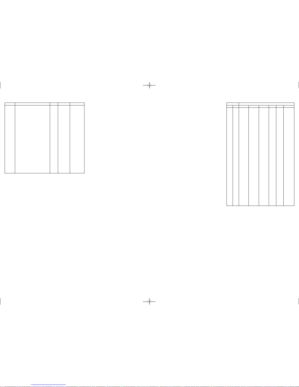
Parameter
SP
CA1
P0
P1
P2
P5
r0
r1
r2
r3
r5
C1
C2
C3
C4
C5
d0
d3
d4
d5
d6
A1
A2
A3
A4
A5
A6
A7
E9
Description
Set point
Ambient probe adjustment
Type of input probe
Decimal point position
Display units
Value displayed during normal operation
Set point differential
Minimum set point value
Maximum set point value
Set point locked
Cooling or heating
Minimum time between compressor starts
Minimum compressor stoppage time
Minimum on time of compressor
Off time of fault cycle
On time of fault cycle
Interval between defrost
Duration of defrost cycle
Defrost on power up
Defrost delay upon power up
Display during defrost cycle
Alarm set point 1
Alarm delay for A1
Alarm 1 type
Alarm delay upon set point modification
Alarm set point 2
Alarm delay for A2
Alarm 2 type
Reserved for future use
Units
Degrees
Degrees
Option
Option
Option
Option
Degrees
Degrees
Degrees
Option
Option
Minutes
Minutes
Seconds
Minutes
Minutes
Hours
Minutes
Option
Minutes
Option
Degrees
Minutes
Option
Minutes
Degrees
Minutes
Option
None
Range
r1 to r2
-25 to 25
0 to 3
0 or 1
0 or 1
0 or 1
0.1 to 99.0
-199.0 to r2
r1 to 1999
0 or 1
0 or 1
0 to 240
0 to 240
0 to 240
0 to 240
0 to 240
0 to 99
0 to 99
0 or 1
0 to 99
0 or 1
-199 to 1999
0 to 240
0 to 4
0 to 240
-199 to 1999
0 to 240
0 to 4
None
Factory Setting
0.0
0.0
0
1
0
0
2.0
0.0
350.0
0
1
0
0
0
10
10
8
0
1
0
1
0.0
0
0
0
0.0
0
0
None
PARAMETER LIST
PARAMETER DESCRIPTION
SP Sets ambient temperature set point between r1 and r2
CA1 Ambient probe calibration adjustment
P0 Type of input probe
0 = J type thermocouple
1 = K type thermocouple
2 = 3 wire Pt100 RTD
3 = 2 wire Pt100 RTD
P1 Position of decimal place
P2 Display engineering units
0 = °C
1 = °F
2 = No units
P5 Value shown during normal operation
0 = Probe temperature
1 = Set point
r0 Set point differential or hysteresis
r1 Minimum value for set point
r2 Maximum value for set point
r3 Set point lock out
0 = Unlocked
1 = Locked
r5 Selection of heating/cooling operation
0 = Cooling
1 = Heating
C1 Minimum time between compressor starts
C2 Minimum time compressor must remain off before being restarted
C3 Minimum time compressor must remain on after being started
C4 During probe error, time compressor is off
C5 During probe error, time compressor is on
d0 Interval of time between defrost cycles
(if 0, defrost will never be activated)
d3 Duration of defrost cycle
d4 Start defrost cycle upon power up
0 = No
1 = Yes
d5 Defrost delay time upon power up (d4 must be 1)
d6 Temperature shown during defrost
0 = Display probe temperature
1 = Display probe temperature up to (set point + r0)
if probe temperature is below (set point + r0) at activation of
defrost cycle. Display probe temperature if the probe
temperature is above (set point + r0) at activation of defrost cycle.
A1 Alarm 1 temperature set point
A2 Alarm 1 not activated unless temperature remains in alarm state
for this time
A3 Alarm 1 type
0 = Alarm disabled
1 = Absolute low alarm (A1)
2 = Absolute high alarm (A1)
3 = Deviation low alarm (SP - A1)
4 = Deviation high alarm (SP + A1)
A4 Temperature alarms not activated for this time after modifications
to set point
A5 Alarm 2 temperature set point
A6 Alarm 2 not activated unless temperature remains in alarm state
for this time
A7 Alarm 2 type
0 = Alarm disabled
1 = Absolute low alarm (A1)
2 = Absolute high alarm (A1)
3 = Deviation low alarm (SP - A1)
4 = Deviation high alarm (SP + A1)
E9 Reserved
RESISTANCE VS TEMPERATURE TABLE
°C
-55
-50
-45
-40
-35
-30
-25
-20
-15
-10
-5
0
5
10
15
20
25
30
35
40
45
50
55
60
65
70
75
80
85
90
95
100
105
110
115
120
125
130
135
140
145
150
°F
-67.0
-58.0
-49.0
-40.0
-31.0
-22.0
-13.0
-4.0
5.0
14.0
23.0
32.0
41.0
50.0
59.0
68.0
77.0
86.0
95.0
104.0
113.0
122.0
131.0
140.0
149.0
158.0
167.0
176.0
185.0
194.0
203.0
212.0
221.0
230.0
239.0
248.0
257.0
266.0
275.0
284.0
293.0
302.0
Temperature
A
607800.00
441200.00
323600.00
239700.00
179200.00
135200.00
102900.00
78910.00
61020.00
47540.00
37310.00
29490.00
23460.00
18780.00
15130.00
12260.00
10000.00
8194.00
6752.00
5592.00
4655.00
3893.00
3271.00
2760.00
2339.00
1990.00
1700.00
1458.00
1255.00
1084.00
939.30
816.80
712.60
623.60
547.30
481.80
425.30
376.40
334.00
297.20
265.10
237.00
B
963849.00
670166.00
471985.00
336479.00
242681.00
176974.00
130421.00
97081.00
72957.00
55329.00
42327.00
32650.00
25392.00
19901.00
15712.00
12493.00
10000.00
8057.00
6531.00
5326.00
4368.00
3602.00
2986.00
2488.00
2083.00
1752.00
1480.00
1255.00
1070.00
915.50
786.60
678.60
587.60
510.60
445.30
389.60
341.90
301.00
265.80
235.30
208.90
186.10
C
289154.70
201049.80
141595.50
100943.70
72804.30
53092.20
39126.30
29.124.30
21887.10
16598.70
12698.10
9795.00
7617.60
5970.30
4713.60
3747.90
3000.00
2417.10
1959.30
1597.80
1310.40
1080.60
895.80
746.40
624.90
525.60
444.00
376.50
321.00
274.65
235.98
203.58
176.28
153.18
133.59
116.88
102.57
90.30
79.74
70.59
62.67
55.83
D
78.32
80.31
82.29
84.27
86.25
88.22
90.19
92.16
94.12
96.09
98.04
100.00
101.95
103.90
105.85
107.79
109.74
111.67
113.61
115.54
117.47
119.40
121.32
123.24
125.16
127.08
128.99
130.90
132.80
134.71
136.61
138.51
140.40
142.29
144.18
146.07
147.95
149.83
151.71
153.58
155.46
157.33
E
783.2
803.1
822.9
842.7
862.5
882.2
901.9
921.6
941.2
960.9
980.4
1000.0
1019.5
1039.0
1058.5
1077.9
1097.4
1116.7
1136.1
1155.4
1174.7
1194.0
1213.2
1232.4
1251.6
1270.8
1289.9
1309.0
1328.0
1347.1
1366.1
1385.1
1404.0
1422.9
1441.8
1460.7
1479.5
1498.3
1517.1
1535.8
1554.6
1573.3
F
2394000.00
1646200.00
1145800.00
806800.00
574400.00
413400.00
300400.00
220600.00
163.500.00
122280.00
92240.00
70160.00
53780.00
41560.00
32340.00
25360.00
20000.00
15892.00
12704.00
10216.00
8264.00
6722.00
5498.00
4520.00
3734.00
3100.00
2586.00
2166.00
1822.60
1540.00
1306.40
1112.60
951.00
815.80
702.20
606.40
525.60
N/A
N/A
N/A
N/A
N/A
Resistance Curves (in Ohms)
T-40T:Layout 1 12/4/09 11:27 AM Page 2
 Loading...