

Modt i975Xa– YDG Quick Manual
AOpen reserves the right to revise all the specifications and information contained in this
document, which are subject to change without notice.
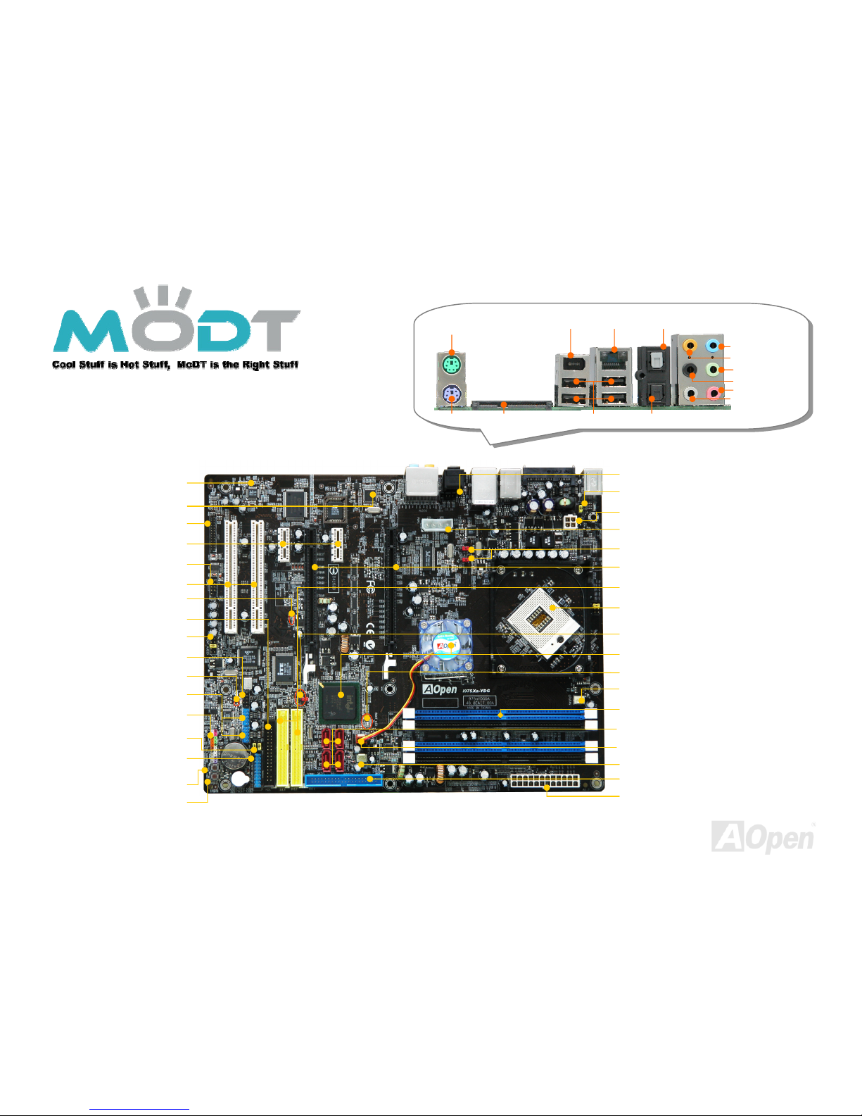
Speaker Out
RJ45 LAN Jack
Line-In
MIC-In
Rear Surround
Sub-woofer
USB 2.0 Ports
Side Surround
IEEE 1394 Port
PS2 Mouse
PS2 Keyboard Serial ATA II S/PDIF In
S/PDIF Out
i975Xa– YDG
i975Xa– YDG
FDD Connector
Power Master II Connector
Power Switch Connector
Reset Switch Connector
Front Panel Connector
USB 2.0 Connector x 2
Power Master Ready II LED
IEEE 1394 Connector
Front Audio Connector
32-bit PCI Expansion Slot x 2
Stand by LED
COM Connector
PCI Express x 1 Slot x 2
Printer Connector
Realtek HDA CODEC
Marvell Gigabit LAN Chip
JP28 PS2 KB/Mouse Wakeup Jumper
4-pin 12V ATX Power Connector
1x4 Peripheral Connector
J4, J5 Front Side Bus Frequency Jumper
PCI Express x16 Slot x 2
479 PIN Socket Supporting Intel Core
Due/Solo Processor
Intel 975X / ICH7
CPU Fan Connector
240-pin DDR II DIMM x 4
Boot LED
24-pin ATX Power Connector
System Fan1 Connector
ATA100 IDE Connector
Serial ATA II Connector x 4
ATA133 IDE Connector x 2
JP14 CMOS Data Clear Jumper
CD_In Connector
Power Fan Connector
Power Master II Jumper
May the Dual Force be with you
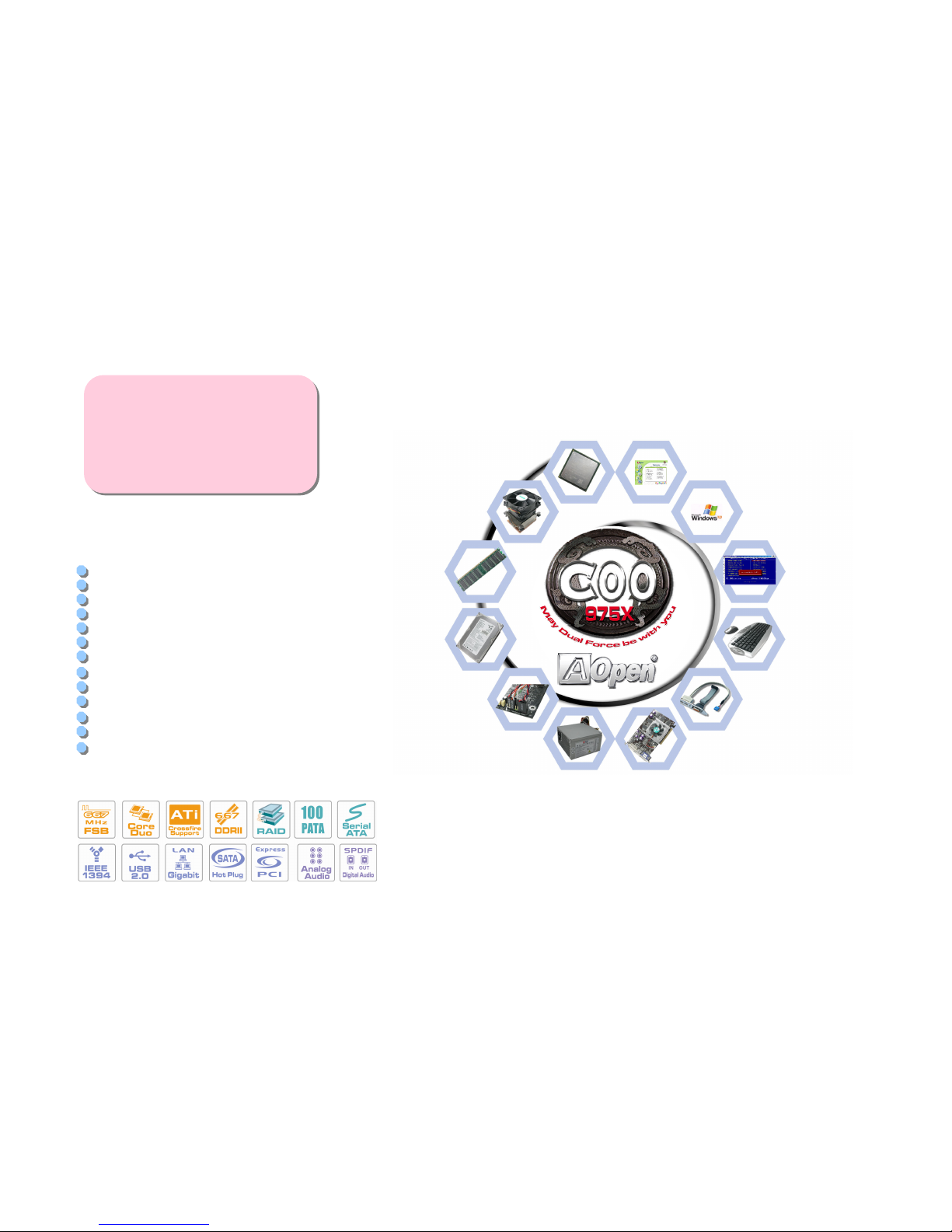
Easy Installation Guide x 1
Enhanced Full Pictured Manual x 1
80-Wire IDE Cable x 1
Floppy Drive Cable x 1
Serial ATA Cable x 1
Serial ATA Power Cable x 1
Hot Plug Serial ATA Cable x 1
Back Panel I/O Shield x 1
CPU Cooler x 1
IR Receiver x 1
IR Remote Control x 1
Bonus Pack CD x 1
ITE IDE RAID Driver Diskette x 1
PART NO: 49.8EM0E.EE10 DOC. NO: I975XAYDG-EG-E0601A
Everything you need is included in
this Easy Installation Guide. For
more information, please refer to
our complete User's Manual in the
Bonus Pack CD.
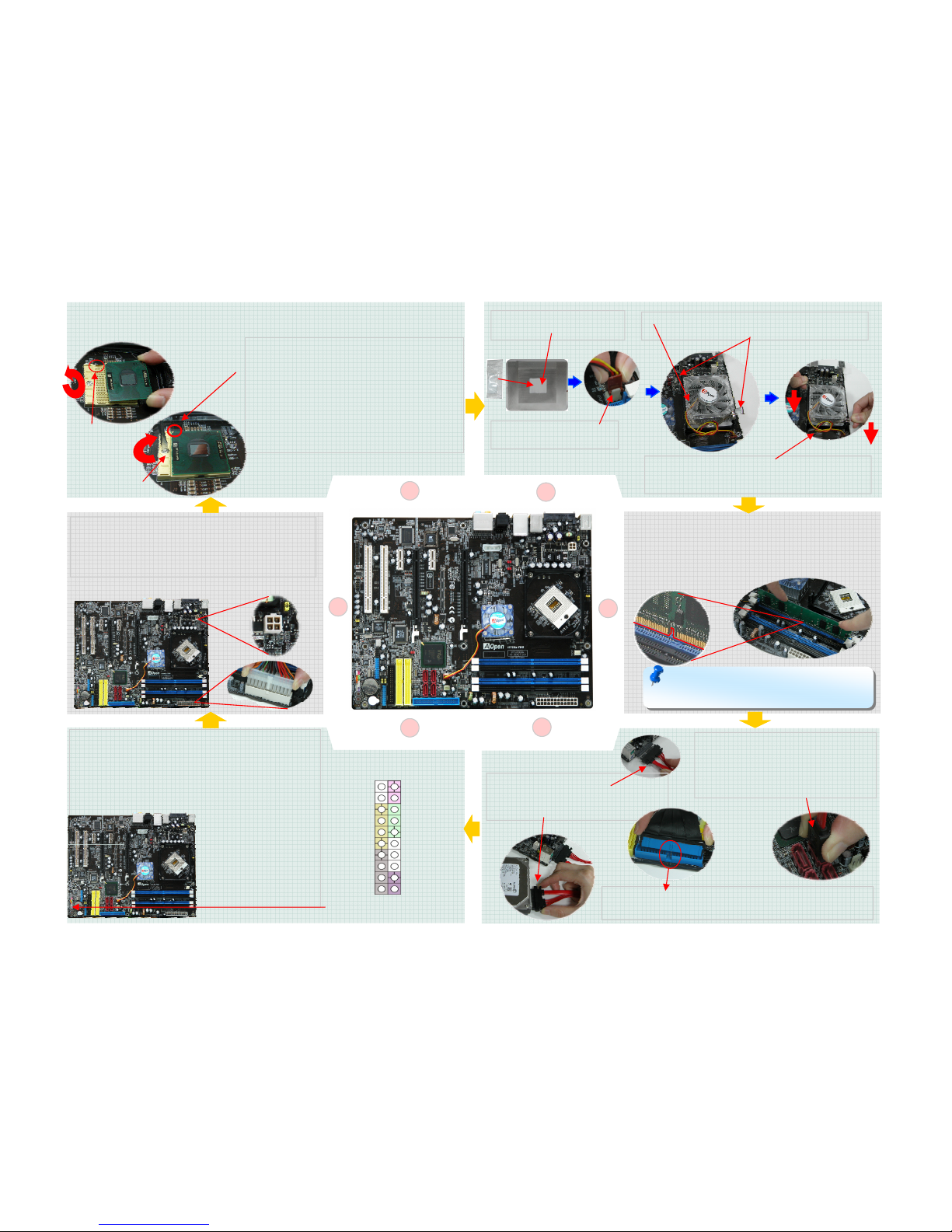
1. Installing CPU
2. Installing CPU Fan
3. Installing
Memory Module
4. Installing HD,
CD-ROM and SATA
6. Connecting ATX
Power Cabl e
5. Connecting Front
Panel Cabl e
7. Installing PCI Express x16
Graphics card & PCI Express
x1 Cards & PCI Cards
8. Installing Other
Devices (USB, Front
Audio, etc)
9. Connecting
Back Panel Ports
(Keyboard, Mouse,
etc)
10. Enter BIOS
setup and setting
CPU Frequency
11. Installing Operating
System such as
Windows XP
12. Installing Drivers & Utilities
Before You Start
Installing By Yourself
Accessory Checklist
4
5
6
1
This socket supports uFCPGA package CPU, which is the latest Yonah Core Duo/Solo
CPU package developed by Intel.
1. Unscrew socket screw counter- clockwise.
2. Locate Pin 1 in the socket and look for a
golden arrow on the CPU upper interface.
Match Pin 1 and golden arrow. Then insert
the CPU into the socket.
3. Lock the socket screw clockwise to fasten
CPU.
Socket Screw
Pin 1
2
Paste the Glue on the center of
Cooler’s back side.
Plug CPU cooler power cable
into power connector.
1. Place CPU cooler properly into CPU retention
2. Plug CPU holder x 2 properly into CPU retention
1. Press CPU holder x 2 in the same time
2. Hook CPU Holder with the hole of retention to
fix CPU cooler
3
DIMM slots are designed in black and navy blue
which are very easy to recognize. Insert the module
straight down to the DIMM slot with both hands and
press down firmly until the DIMM module is securely
in place.
Note: The tabs of the DIMM slot will close-up to hold the
DIMM in place when the DIMM touches the slot’s bottom.
External Hot Plug SATA HDD:
1. Plug SATA cable to onboard External
SATA Connector properly
2. Plug SATA cable to SATA HDD
1. Plug IDE cable into IDE connector with IDE HDD
2. Take care the direction of cable to meet the hole in IDE slot
Internal SATA HDD Connection:
1. Plug SATA cable to onboard internal
SATA Connector properly
2. Plug SATA cable to SATA HDD
3. Plug Power connector to SATA HDD
Power Switch
1
Front Panel Connector
GND
Power LEDGND
Power LED+
GND
NC
GND
RESET
GND
NC
NC
+5V
HDD LED
HDD LED
+5V
+5V
GND
NC
SPEAKER
Attach the power LED, speaker, and reset switch
connectors to the corresponding pins. If you enable
“Suspend Mode” item in BIOS Setup, the ACPI &
Power LED will keep flashing while the system is in
suspend mode. Locate the power switch cable from
your ATX housing. It is
2-pin female
connector from the
housing front panel.
Plug this connector to
the soft-power switch
connector marked
1. Plug CPU power 4pins cable to CPU power connector
2. Plug ATX power cable to power connector on board
Above two cables and connector had directional
mechanism. Please plug it according it. If not plug or not
plug properly, the MB will not work.
 Loading...