

Page 1
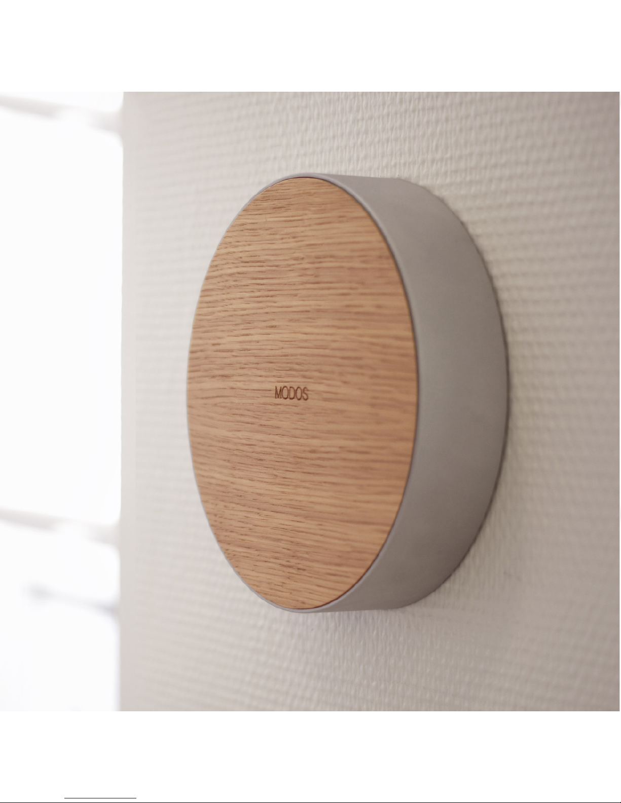
MODOS one
INSTALLATION MANUAL
Page 2
2
Page 3

1
Welcome to the MODOS family
This guide provides steps on how to set up your MODOS one.
Page 4

2
INDEX
1. SAFETY AND HANDLING 4
2. OVERVIEW
Components 8
Contents 10
Before you start 12
2: SETUP
Installation instructions 14
3: CABLING
MODOS one connector diagram 26
Connecting cables to the MODOS one 28
4: CONFIGURATION 36
5: TECHNICAL DATA 38
6: SERVICE AND SUPPORT 40
7: PRODUCT MARKINGS & OTHER INFORMATION 42
Page 5

3
Page 6

4
1. SAFETY AND HANDLING
WARNING: Read all safety information below and operating instructions
before using your MODOS one to avoid injury. Failure to follow these safety
instructions could result in fire, electric shock, or other injury or damage to
your MODOS one or other property.
• Read these instructions.
• Keep these instructions.
• Heed all warnings.
• Follow all instructions.
• Do not use your MODOS one near water.
• Do not install near any heat sources such as radiators, heat register
vents, stoves or other devices that produce heat.
• Unplug your MODOS one during lightning storms.
• Refer all servicing to qualified service personnel. Servicing is required
when your MODOS one has been damaged in any way, such as when
cables are damaged, liquid has been spilled into your MODOS one, or
it has been exposed to rain or moisture, does not operate normally, or
has been dropped.
Power: Your MODOS one has no on/off switch. To disconnect your MODOS
one from power, unplug the power lead. When connecting or disconnecting
your MODOS one, always hold the plug by its sides. Keep fingers away from
the metal part of the plug.
Page 7

5
Location: Do not use your MODOS one outdoors. The MODOS one is an
indoor product. Do not place naked flame sources, such as lighted candles,
on or near your MODOS one. Do not use your MODOS one near water. Do
not expose your MODOS one to dripping or splashing. Do not move your
MODOS one if cables are connected to it.
Jacks and terminals: Never force a connector into a jack. When installing
wires into the terminal blocks on the MODOS one, 3 mm of wire should be
exposed. Press down on the top of the terminal with a screwdriver and push
the wire into the terminal.
Cleaning and care: To clean your MODOS one, use a soft, dry, lint-free
cloth. Avoid getting moisture in openings. Don’t use window cleaners,
household cleaners, aerosol sprays, solvents, alcohol, ammonia or abrasives
to clean your MODOS one.
Handling: Your MODOS one may be damaged by improper storage or
handling. Be careful not to drop your MODOS one when transporting it.
If your MODOS one has a glass face and it gets cracked or damaged,
exercise caution when handling the unit and order a replacement cover.
Operating temperature: Your MODOS one works best in ambient
temperatures between 0° and 35° C (32° and 95° F) and can be stored at
temperatures between -20° and 45° C (-4° and 113° F).
Device information: Information such as the model number, serial number
Page 8

6
and electrical rating is located on the mounting plate inside your MODOS
one.
Use with medical-grade equipment: The MODOS one has not been
tested for use as a controller for medical-grade equipment, and as such
should not be used to control monitoring equipment and other sensitive
devices.
Electrical surge protection: To prevent risk of shock and/or damage to
your MODOS one, always use an in-line electrical surge protection device
between your MODOS one and the mains power.
Page 9

7
Page 10

8
The MODOS one is a sophisticated room management device that connects
and controls all elements in a room.
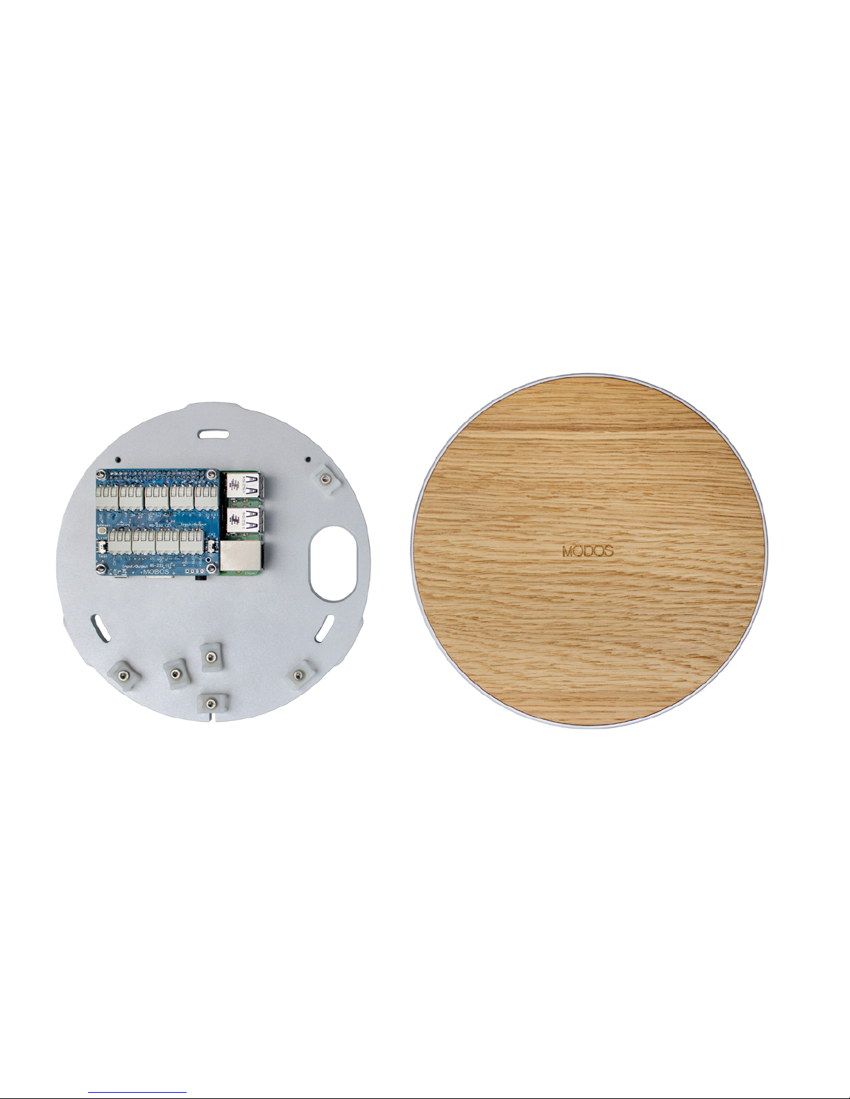
Your new MODOS one consists of three parts: the front cover, the
electronics, and the wall mounting plate. In the following section we will
show you how to install your MODOS one in your room.
2. OVERVIEW
COMPONENTS
Page 11
9
MOUNTING PLATE,
CLIPS, ELECTRONICS
COVER
Page 12
10
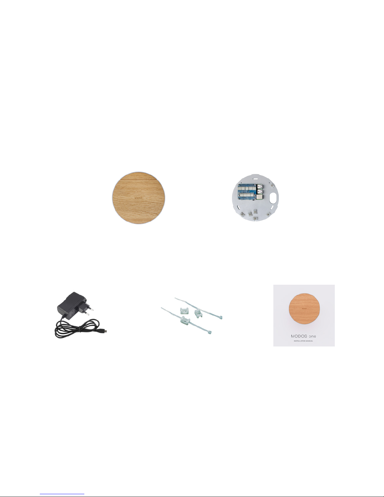
ManualPower supply Cable ties & clips
Here’s what’s in the box:
Case & faceplate Mounting plate
& electronics
CONTENTS
Page 13
11
Page 14
12
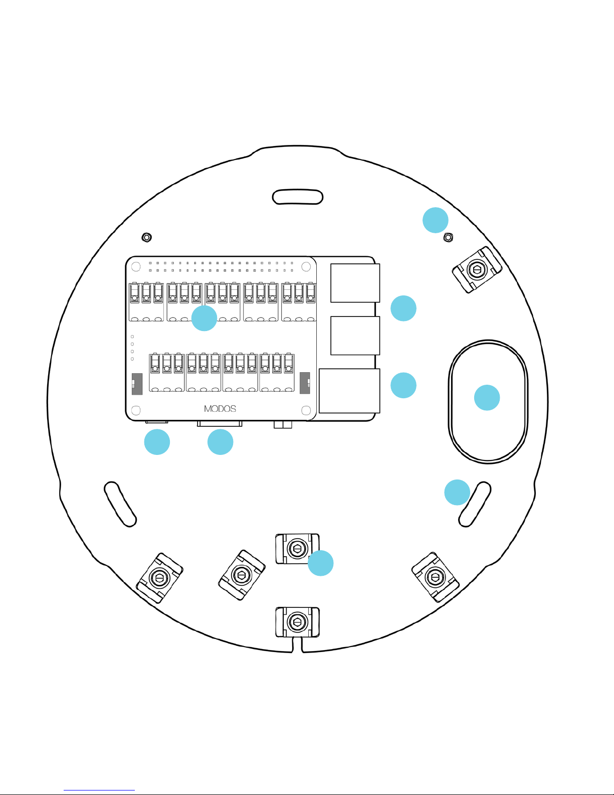
BEFORE YOU START
The following overview of the installation process should be understood
before mounting your MODOS one on the wall.
REMOVING THE COVER
To open the MODOS one, unscrew the securing screw located at the
bottom of the unit. The cover can then be rotated counter-clockwise and
removed to expose the contents.
A
B
C
D
E
F
G
H
I
Connector terminal
Horizontal alignment guides
Mounting holes
USB
Ethernet
Cable tie clips
Cable hole
Power jack
HDMI
WHAT’S INSIDE
Page 15
13
A
H
I
F
C
G
E
D
B
Page 16

14
2. SETUP
INSTALLATION INSTRUCTIONS
Page 17
15
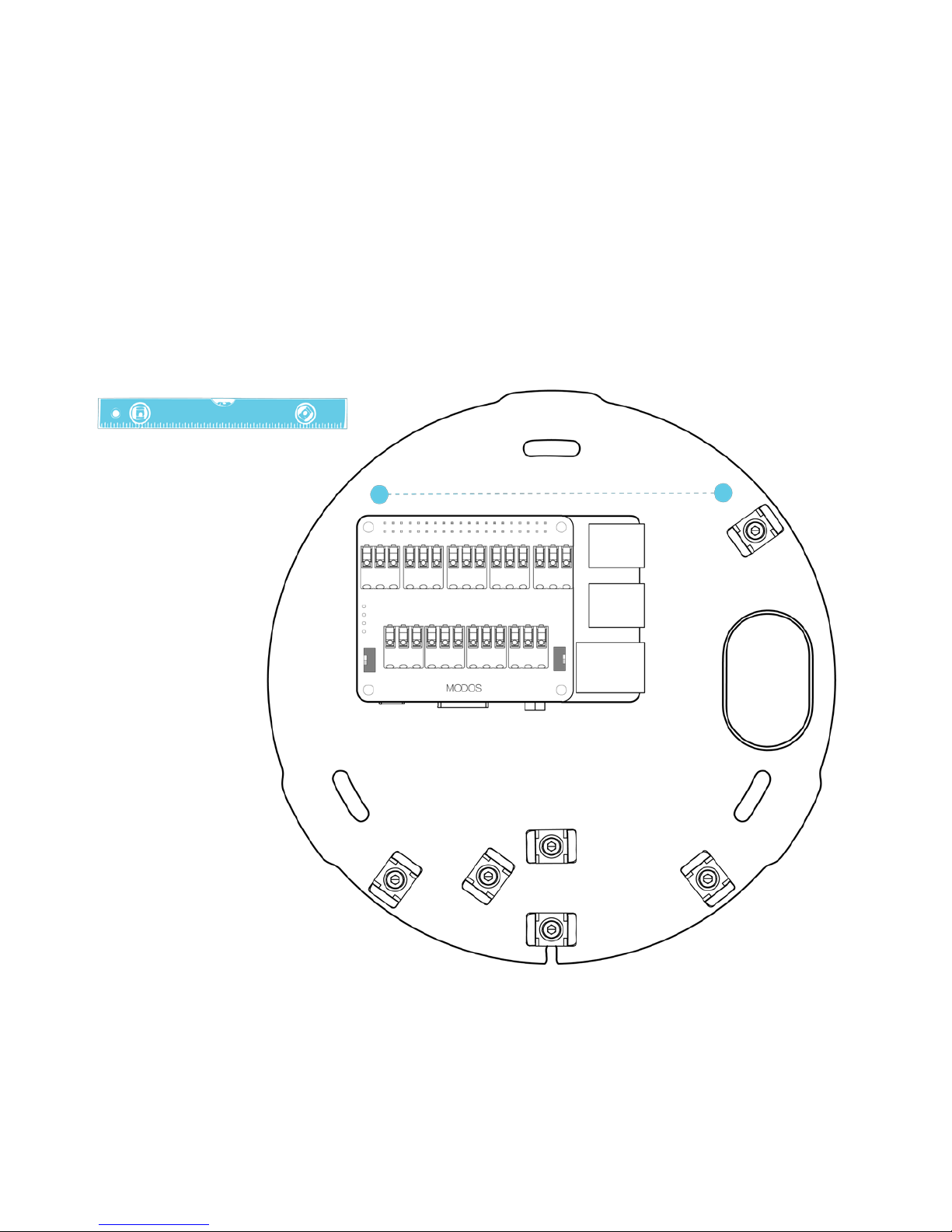
Step 1: Using a level, align the mounting plate against the wall so that the
two horizontal guide holes are level.
Page 18
16
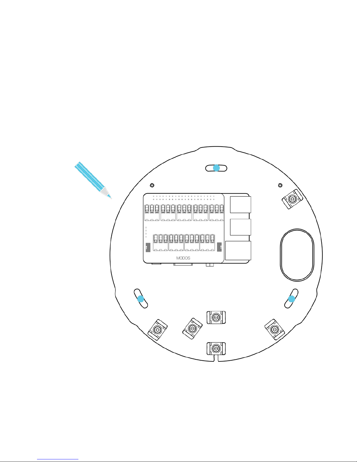
Step 2: Use a pencil to mark the points where the holes will be drilled for the
mounting screws.
Page 19
17
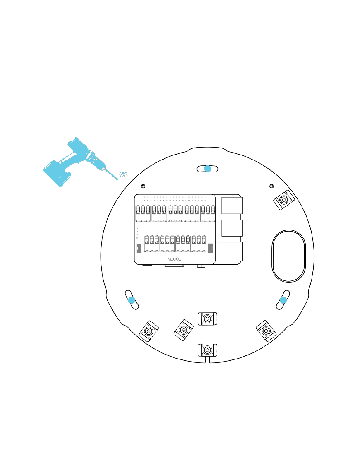
Step 3: Remove the mounting plate from the wall and use a 3mm drill bit to
drill the mounting holes, using wall anchors where necessary.
Page 20
18
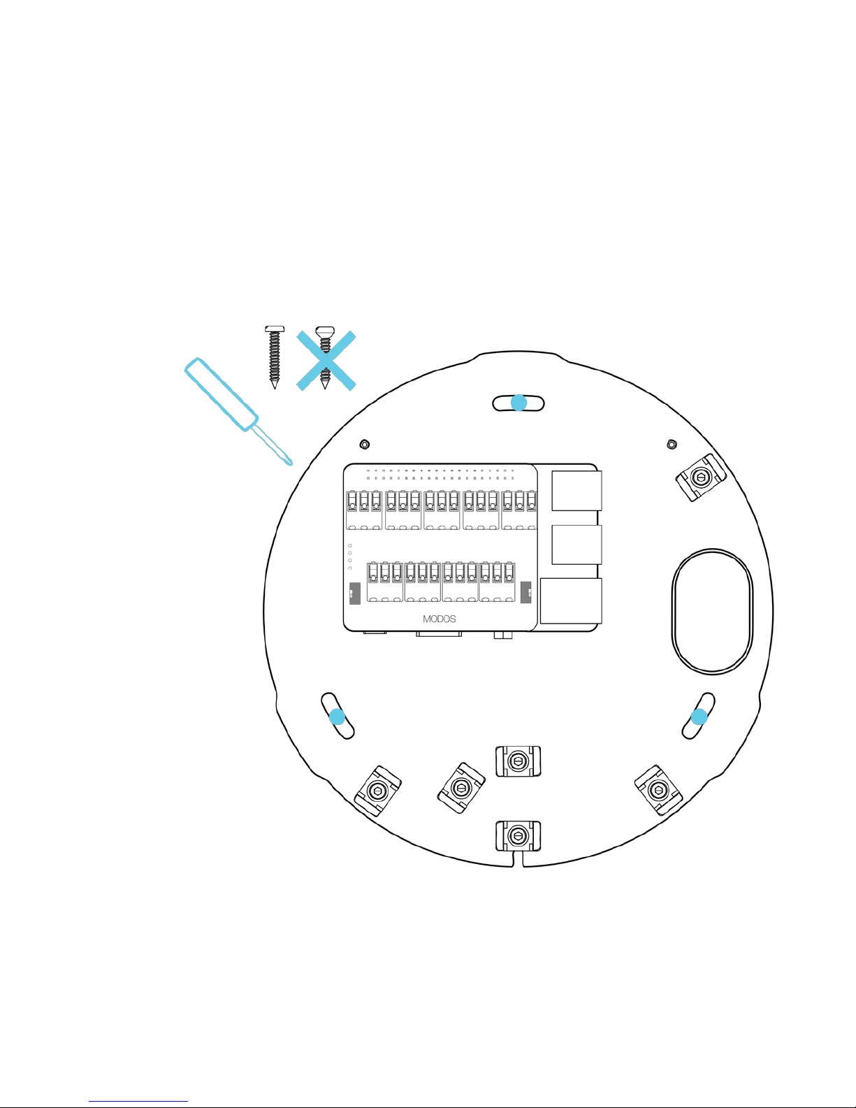
Step 4: Using pan-headed screws, affix the mounting plate to the wall. Do
not use screws with tapered heads, as this can damage the mounting plate.
Page 21
19
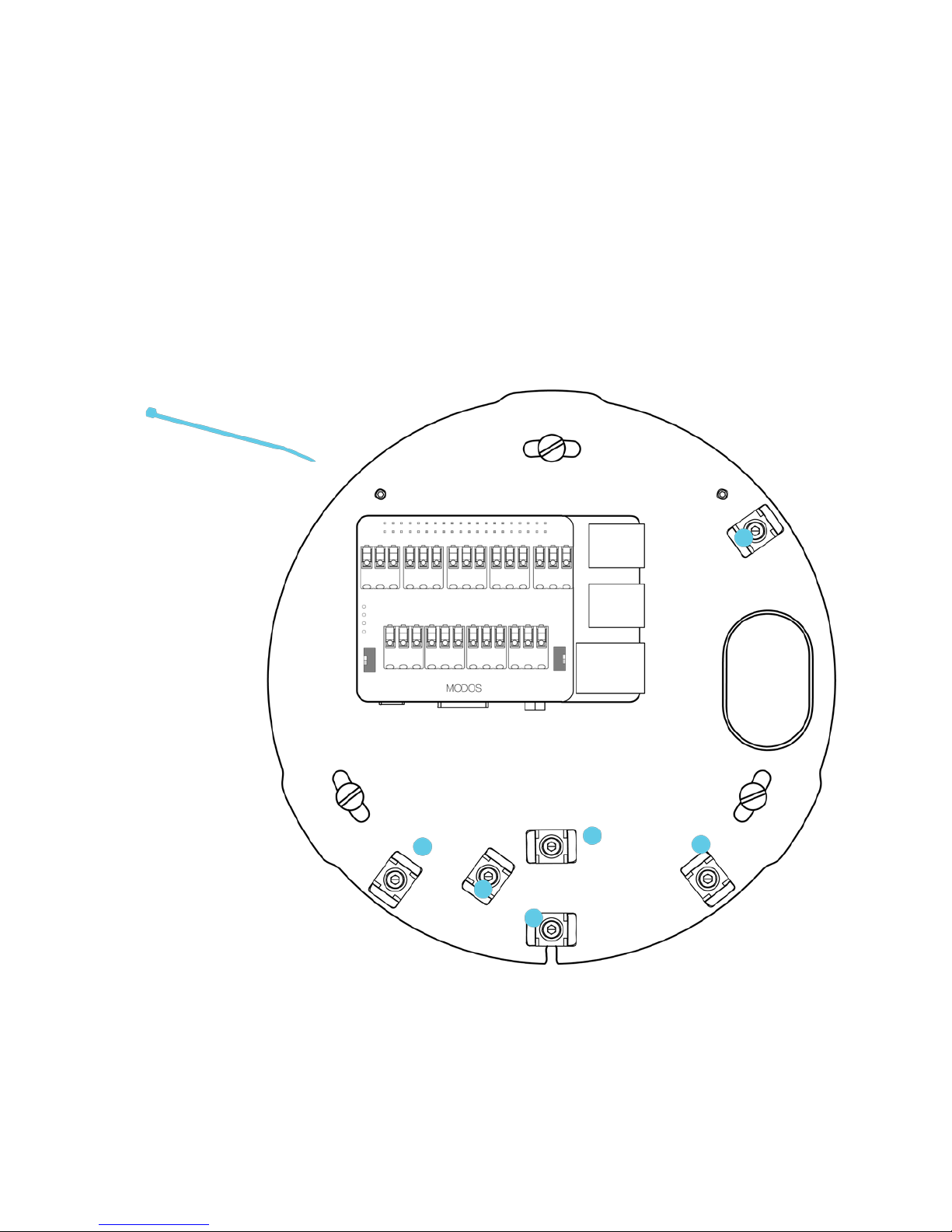
Step 5: Insert the cable ties through the mounting clips and leave them open
for now - they are used for cable management in the next steps.
Page 22
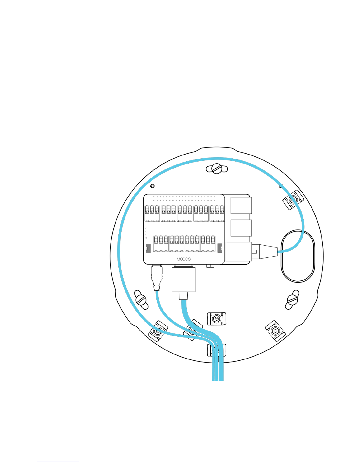
20
FOR CABLE-ON-WALL INSTALLATION:
Step 6: Plug in the power, HDMI, and ethernet cables, using the cable ties
to securely route the cables to the cable exit hole.
Page 23
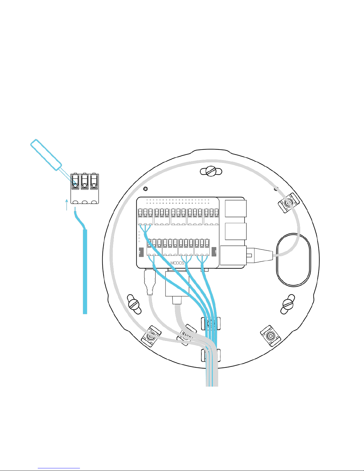
21
FOR CABLE-ON-WALL INSTALLATION:
Step 7: Using a flat-head screwdriver, press down on the terminal
connectors and inser the wires into the MODOS one board. Route the
cables through the cable ties as necessary.
Page 24
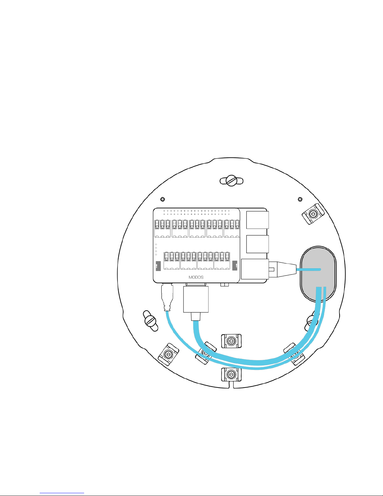
22
FOR CABLE-IN-WALL INSTALLATION:
Step 6: Plug in the power, HDMI, and ethernet cables, using the cable ties
to securely route the cables to the cable exit hole.
Page 25
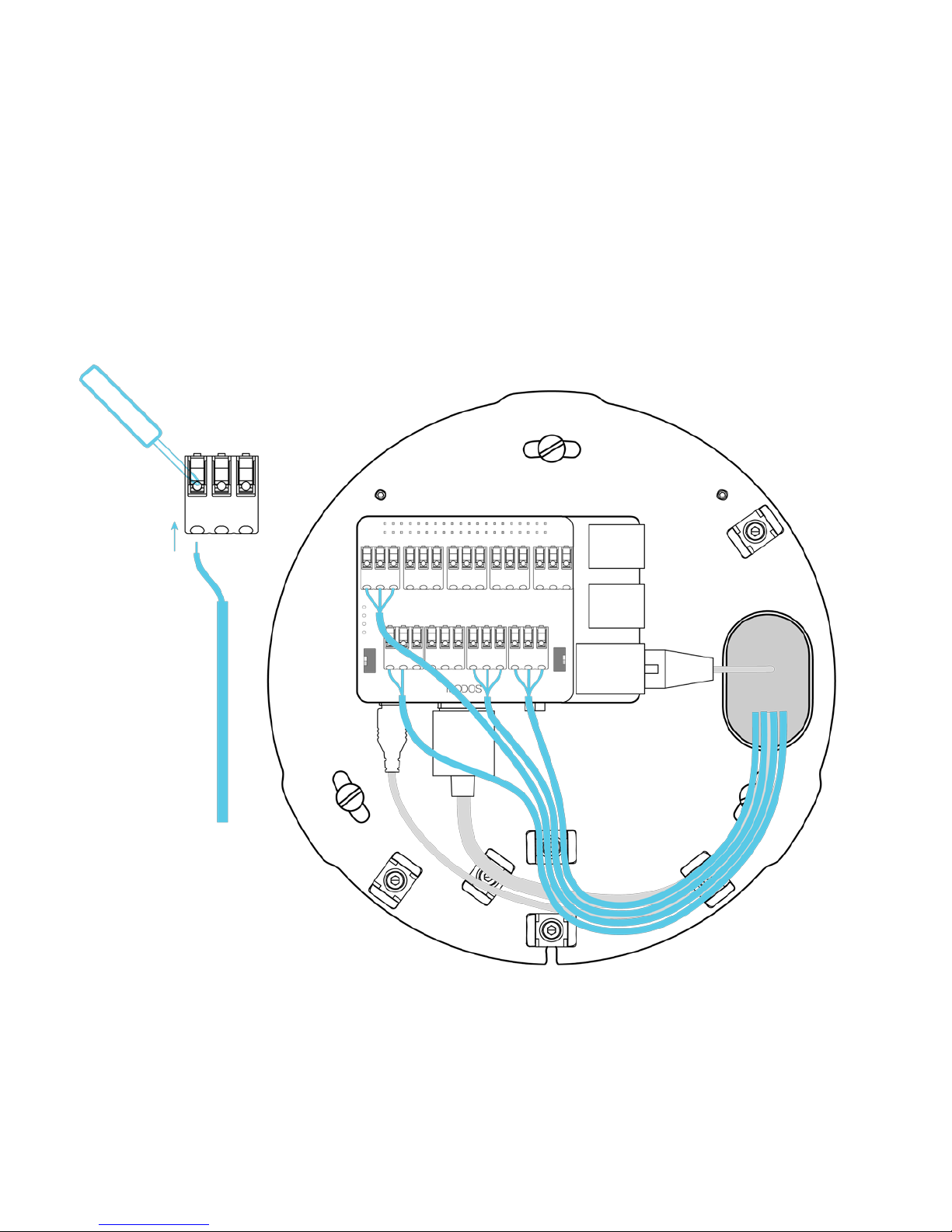
23
FOR CABLE-IN-WALL INSTALLATION:
Step 7: Using a flat-head screwdriver, press down on the terminal
connectors and inser the wires into the MODOS one board. Route the
cables through the cable ties as necessary.
Page 26
24
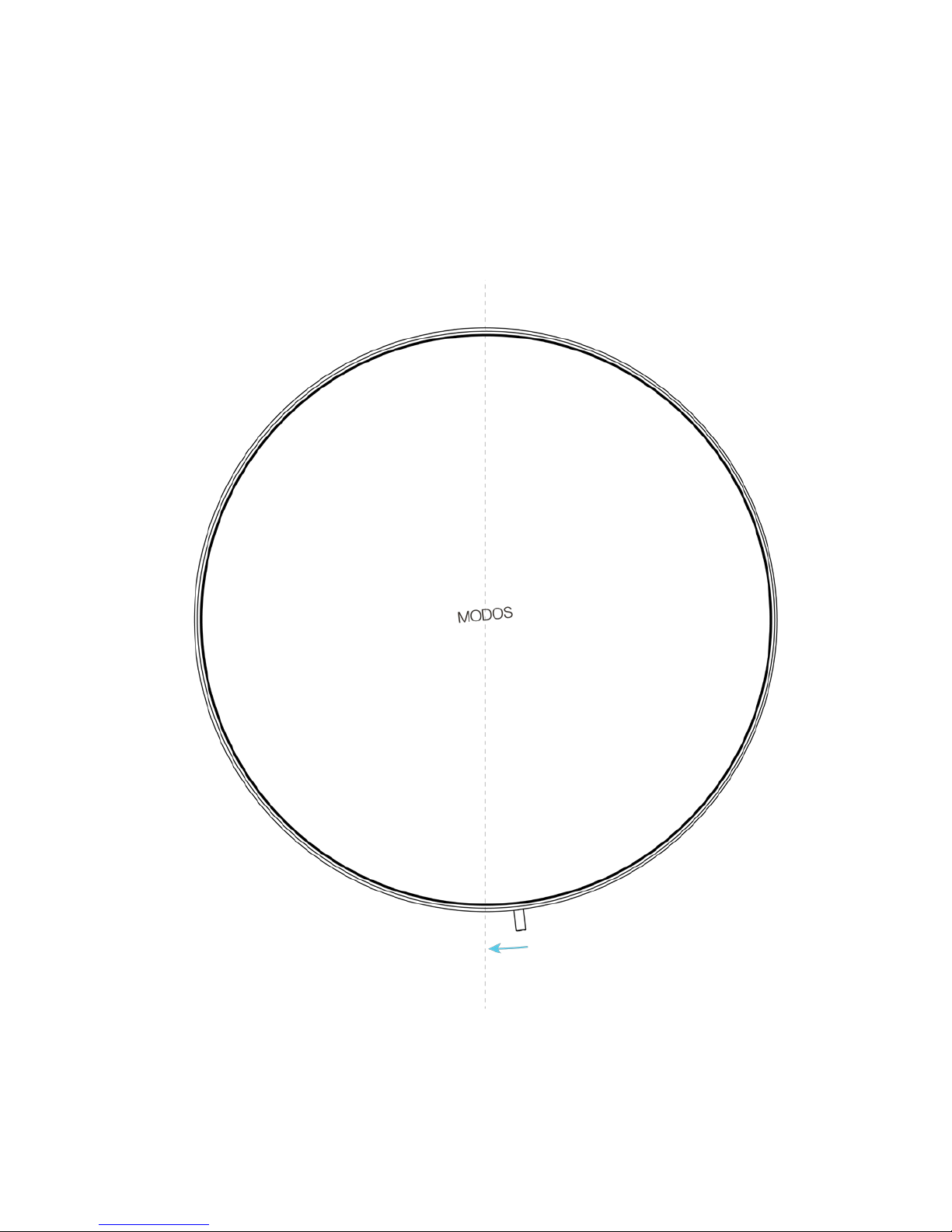
Step 8: Place the cover on the mounting plate, and turn it slightly to lock it
in place.
Page 27
25
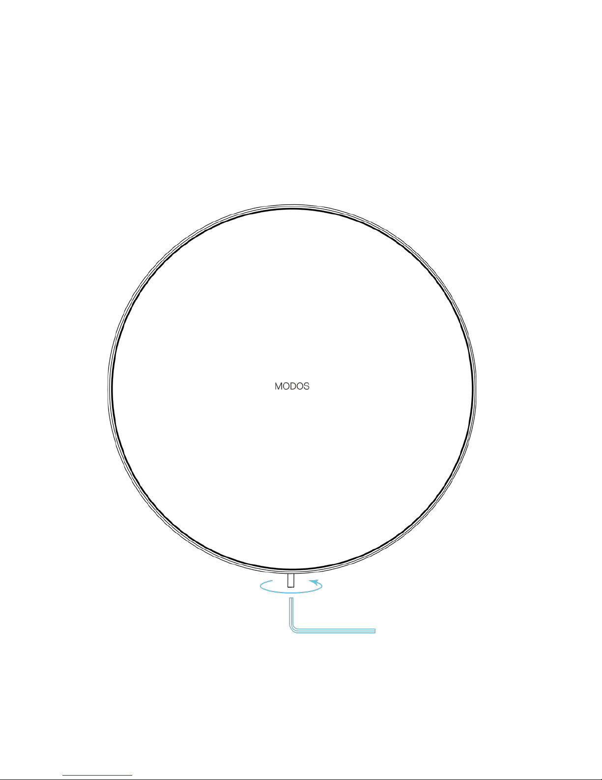
Step 9: Use a hex key to secure the cover in place using the screw at the
bottom of the case. The MODOS one is now safely mounted on the wall.
Page 28

26
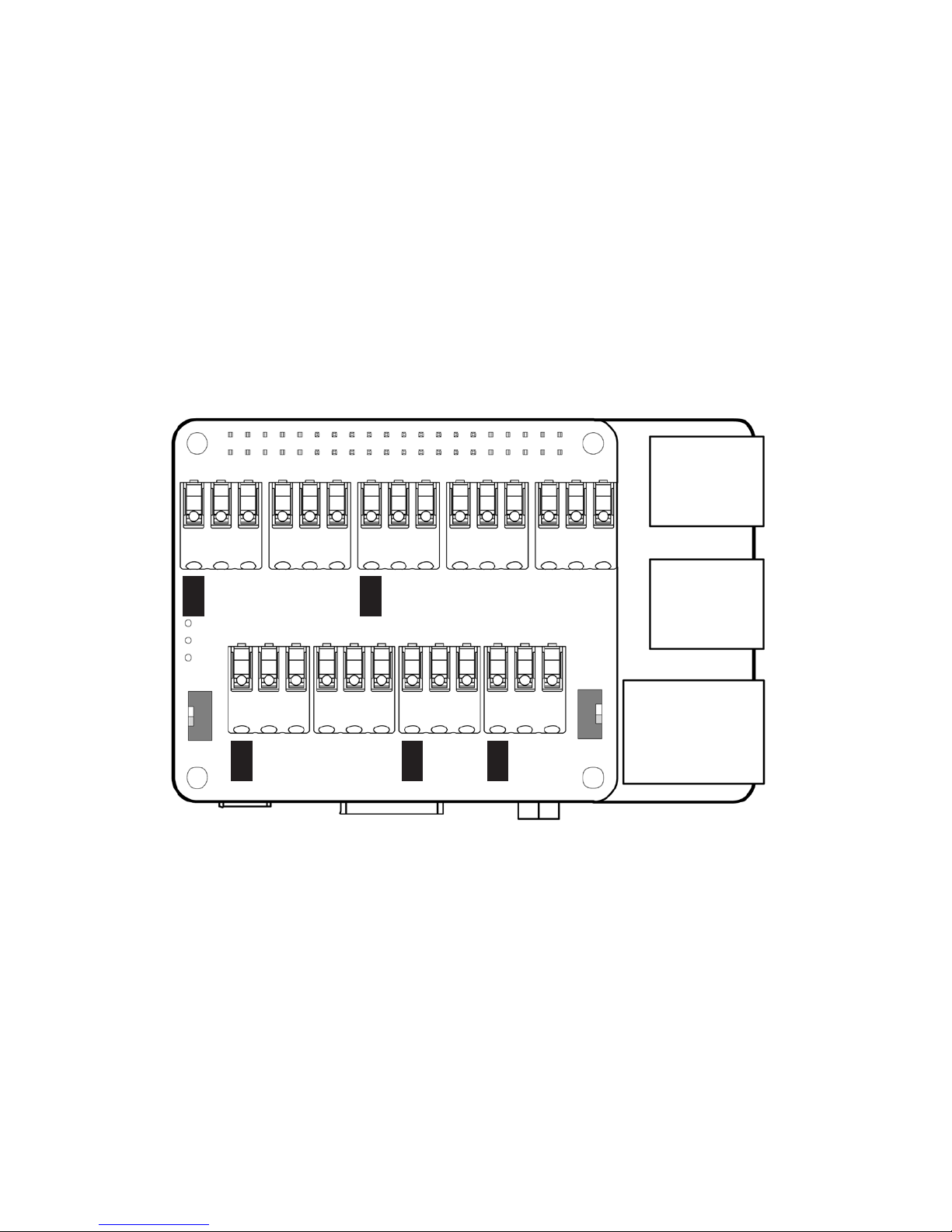
MODOS ONE CONNECTOR DIAGRAM
3. CABLING
+5V output : +5V
RS-232 input #1 : GND, Tx1, Rx1
RS-232 input #2 : GND, Tx2, Rx2
Digital input/output : IO1 - IO10
Analogue input/output : A1 - A4
DMX output : GND, DMX-, DMX+
External power supply input : EXT, GND (set 5V/EXT switch to EXT)
Page 29
27
GND
+5V
GND
Tx2
Rx2
A1
A2
A3
A4
IO6
IO7
IO8
IO9
IO10
EXT
GND
IO1
IO2
IO3
Rx1
GND
DMX-
DMX+
RS-232(2)
RS-232(1) DMX
EXT
5V
IO4
IO5
GND
Tx1
Page 30

28
A
B
C
Ethernet jack
Power jack
HDMI cable
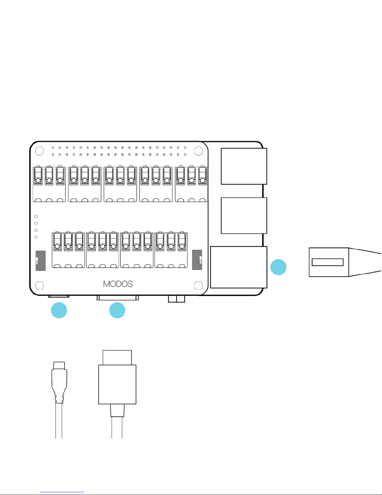
Step 1: Insert the ethernet, power, and HDMI cables into the proper jacks
on the MODOS one board.
CONNECTING CABLES TO THE MODOS ONE
Page 31
29
ETHERNET
HDMIPOWER
A
B C
Page 32
30
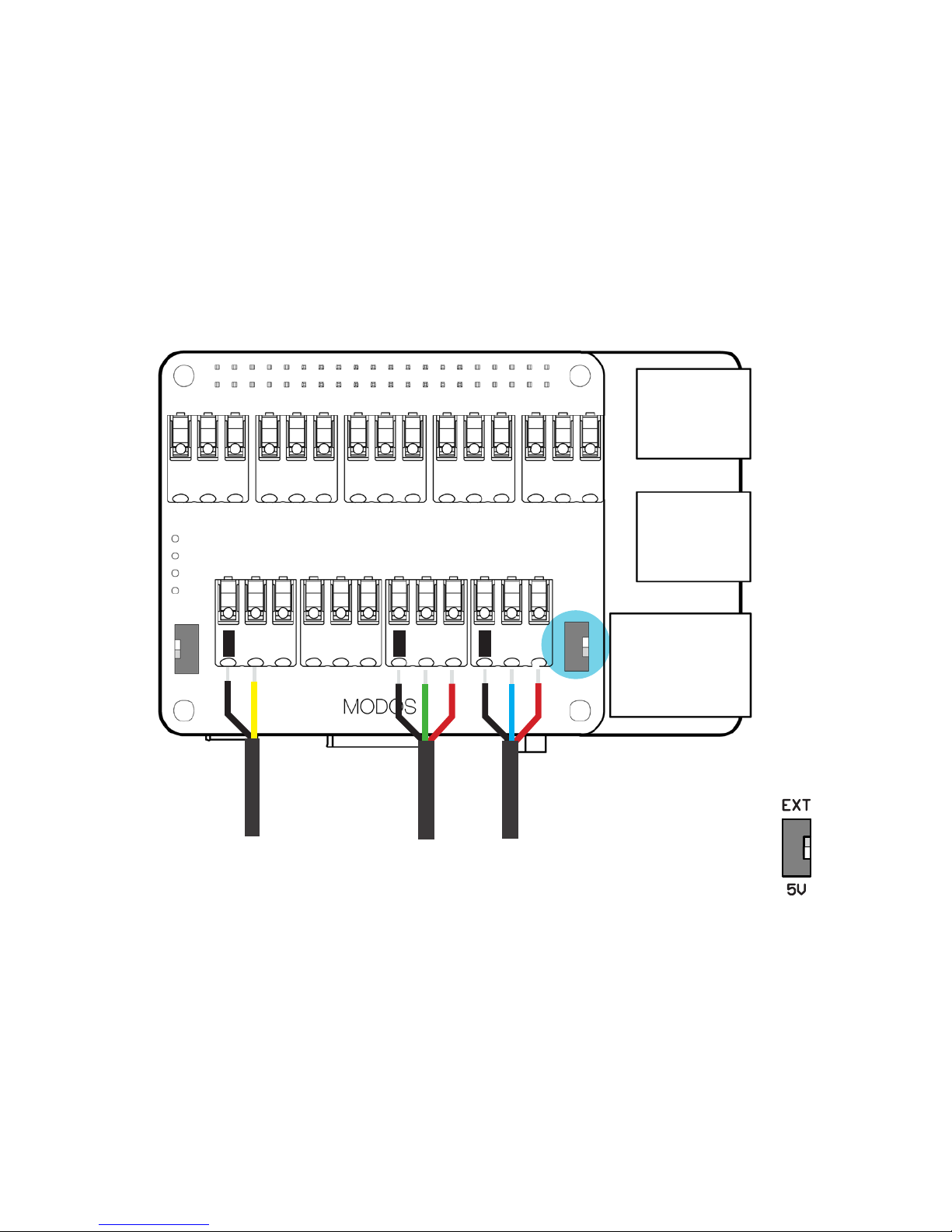
Step 2: Connect switches, sensors, lights, and other devices to the MODOS
one board.
CONNECTION SPECIFICATIONS
Inputs for switches and digital sensors:
• Switches/sensors being used with the MODOS one must be default
open types (eg. open collector type).
• Connect the switch/sensor between one of the digital IO connectors
(IO1-IO10) and GND.
• Use 0.5 mm2 shielded cable, max. 20 m long. Remember to ground
the shielding.
• The voltage level of the IO connectors is 5V when the 5V/EXT switch is
in the 5V position. When the switch is in the EXT position, the voltage
level of the IO connectors will match the source voltage of the external
power supply connected to the MODOS one. Using switches/digital
sensors with different input voltages will require external voltage level
conversion.
5V output:
• Use +5V and a GND connector to power external devices requiring 5V.
• The MODOS one board can supply up to 490 mA total across all
connectors.
Using an external power supply:
• Set the 5V/EXT switch to EXT if using an external power supply.
Page 33
31
DMXRS232 DIGITAL
SWITCH
Example connections for a digital switch, RS-232,
and DMX
EXT/5V
switch
detail
GND
IO1
GND
Tx1
Rx1
GND
DMX-
DMX+
Page 34

32
• Connect the external power supply to EXT and GND.
• The voltage level of the IO connectors will match the source voltage of
the external power supply connected to the MODOS one.
• The max voltage for an external power supply is 24V.
DMX:
• Connect the first lamp’s DMX+, DMX-, and GND to DMX+, DMX-, and
GND on the MODOS one respectively.
• The cable type should be shielded twisted pair with a max cable length
of 500 m, and the DMX+/DMX- wires should be paired in the cable.
Serial (RS-232):
• The MODOS one board offers two RS-232 ports for controlling devices
using serial RS-232 communication.
• To connect an external device to the MODOS one:
Tx on the external device to Rx1/2 on the MODOS one
Rx on the external device to Tx1/2 on the MODOS one
GND on the external device to GND on the MODOS one
• The cable type should be RS-232 cable with a max cable length of 15
m at 9600 baud.
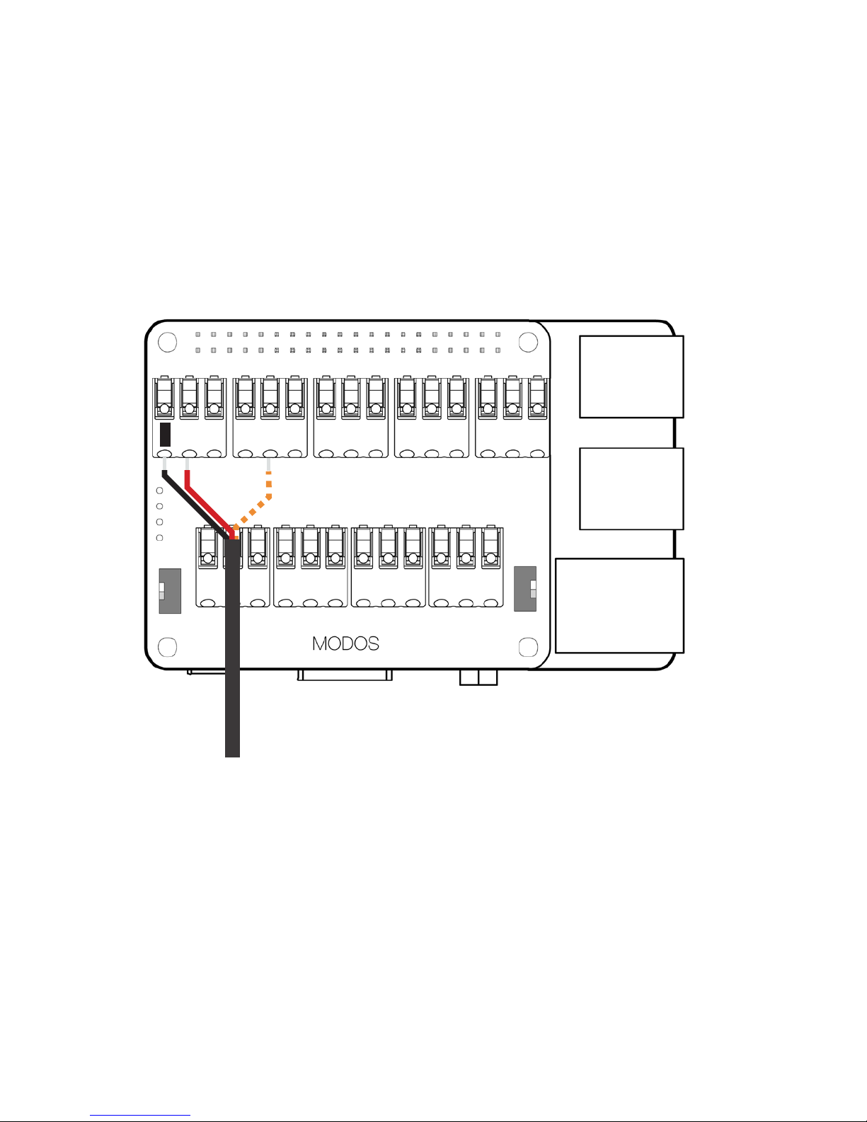
Analogue inputs for switches and analogue sensors:
• Connect the switch/sensor between one of the analogue IO connectors
(A1-A4) and GND.
• Use 0.5 mm2 shielded cable, max. 20 m long. Remember to ground
the shielding.
Page 35
33
ANALOGUE
SWITCH
Example connections for an analogue switch
GND
+5V
A3
Page 36

34
• The voltage level of the IO connectors is 5V when the 5V/EXT switch is
in the 5V position. When the switch is in the EXT position, the voltage
level of the IO connectors will match the source voltage of the external
power supply connected to the MODOS one. Using switches/analogue
sensors with different input voltages will require external voltage level
conversion.
• The voltage output of the analogue switch/sensor must be between
0-3.3V.
Page 37

35
Page 38

36
4. CONFIGURATION
The technician installing your MODOS one system will use the technician
setup guide to configure the various connected devices in your room.
You can find the latest version of the technician setup guide at
www.modos.dk/downloads.
Page 39

37
Page 40
38
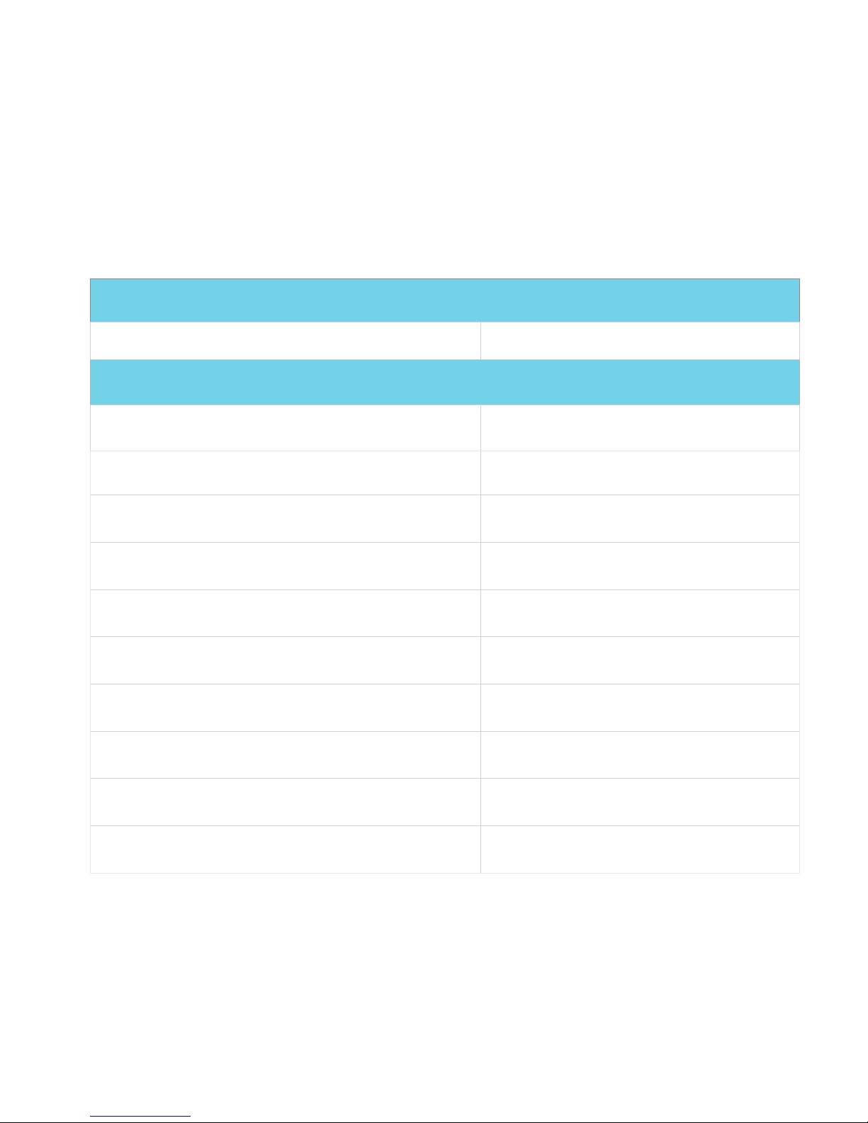
Model
MODOS one v0.5
General specifications
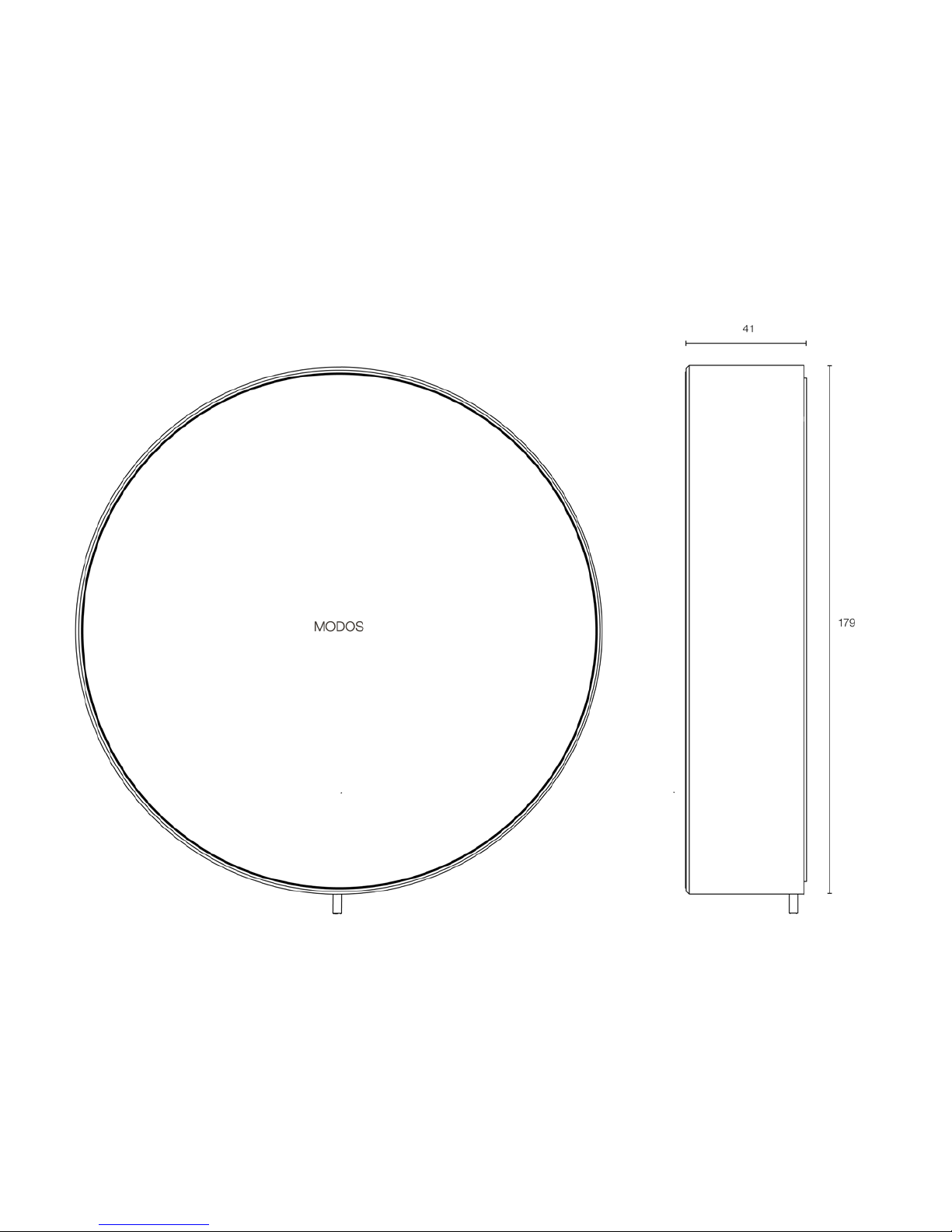
Dimensions (diameter x depth) 179 x 41 mm
Weight 750 g (wood), 900 g (glass)
Power 5V DC
Operating temperature 0 - 40 ºC
Operating humidity 0 - 80%, no condensation
Protection class IP20
Materials Aluminum, glass, wood
Input GPIO
Output 5V, DMX, RS-232
Certification CE
5. TECHNICAL DATA
Page 41
39
DIMENSIONS
ALL DIMENSIONS IN MM
Page 42

40
6. SERVICE AND SUPPORT
If you need help with installing your MODOS one or configuring it, visit our
website at www.modos.dk/support to get access to guides, videos, and
more.
Page 43

41
Page 44
42
MODOS Aps. declares that the MODOS one complies with the essential
requirements and other relevant provisions of directives 2014/30/EU EMC,
2014/35/EU Low Voltage, 2011/65/EU ROHS, and the WEEE directive.
PRODUCT DISPOSAL
In order to help reduce the impact of electronic waste on the environment,
the MODOS one requires specialised disposal.
This symbol indicates that your product must be disposed of separately from
household waste. When you decide to dispose of the product, you must do
so in accordance with local environmental laws and guidelines.
7. PRODUCT MARKINGS & OTHER INFORMATION
Page 45

43
© 2016 MODOS Aps. All rights reserved.
Under applicable copyright laws, all or part of this material may not be
copied without prior written consent from MODOS.
MODOS
Skivevej 2
7500 Holstebro
Denmark
www.modos.dk
The MODOS logo is a trademark of MODOS Aps. Using the MODOS logo
for commercial purposes without prior written consent from MODOS may
constitute trademark infringement and unfair competition and be in violation
of Danish law.
MODOS one is covered under EU-Trademark No. 014556229.
MODOS one manual v0.5 2016-10
 Loading...