

Page 1
MODOR DIGITAL POLYPHONIC SYNTHESIZER
USER MANUAL
Page 2

Page 3

Contents
1 Getting Started . . . 1
1.1 Connections and settings . . . . . . . . . . . . . . . . . . . . . . . . 1
1.2 Menu navigation . . . . . . . . . . . . . . . . . . . . . . . . . . . . 2
1.3 Loading patches . . . . . . . . . . . . . . . . . . . . . . . . . . . . . 3
1.4 Saving patches . . . . . . . . . . . . . . . . . . . . . . . . . . . . . 3
1.5 Patch initialisation . . . . . . . . . . . . . . . . . . . . . . . . . . . 4
2 Overview 5
2.1 Structure of a patch . . . . . . . . . . . . . . . . . . . . . . . . . . . 5
2.2 Frontpanel overview . . . . . . . . . . . . . . . . . . . . . . . . . . 6
3 Oscillator section 9
3.1 Using the oscillators . . . . . . . . . . . . . . . . . . . . . . . . . . 9
3.2 Oscillator waveforms . . . . . . . . . . . . . . . . . . . . . . . . . . 10
3.2.1 Sawtooth PWM oscillator . . . . . . . . . . . . . . . . . . . 10
3.2.2 Square PWM oscillator . . . . . . . . . . . . . . . . . . . . . 11
3.2.3 Triangle PWM oscillator . . . . . . . . . . . . . . . . . . . . 11
3.2.4 Sync oscillator . . . . . . . . . . . . . . . . . . . . . . . . . 12
3.2.5 Additive harmonics oscillator . . . . . . . . . . . . . . . . . 12
3.2.6 Sonar noise oscillator . . . . . . . . . . . . . . . . . . . . . . 13
3.2.7 Wind noise oscillator . . . . . . . . . . . . . . . . . . . . . . 13
3.2.8 Arcade noise oscillator . . . . . . . . . . . . . . . . . . . . . 14
3.2.9 Sine FM oscillator . . . . . . . . . . . . . . . . . . . . . . . 14
3.2.10 Sine feedback FM oscillator . . . . . . . . . . . . . . . . . . 16
3.3 White noise . . . . . . . . . . . . . . . . . . . . . . . . . . . . . . . 16
3.4 Ring modulator . . . . . . . . . . . . . . . . . . . . . . . . . . . . . 17
4 Filter section 18
4.1 LP/HP/BP/BS filter . . . . . . . . . . . . . . . . . . . . . . . . . . . 18
4.2 Formant filter . . . . . . . . . . . . . . . . . . . . . . . . . . . . . . 20
4.3 Filter configuration . . . . . . . . . . . . . . . . . . . . . . . . . . . 22
i
Page 4

5 Amplifier section 23
6 Effects section 24
6.1 Chorus/Flanger effect unit . . . . . . . . . . . . . . . . . . . . . . . 24
6.2 Delay effect unit . . . . . . . . . . . . . . . . . . . . . . . . . . . . . 26
7 Modulation section 28
7.1 LFOs . . . . . . . . . . . . . . . . . . . . . . . . . . . . . . . . . . 28
7.2 Sample&Hold . . . . . . . . . . . . . . . . . . . . . . . . . . . . . . 29
7.3 Envelopes . . . . . . . . . . . . . . . . . . . . . . . . . . . . . . . . 30
7.4 Modulation Matrix . . . . . . . . . . . . . . . . . . . . . . . . . . . 31
7.5 Pitch Modulation . . . . . . . . . . . . . . . . . . . . . . . . . . . . 33
7.6 Amplitude Modulation . . . . . . . . . . . . . . . . . . . . . . . . . 34
7.7 Other popular modulations . . . . . . . . . . . . . . . . . . . . . . . 35
8 Menu Reference 37
8.1 Load . . . . . . . . . . . . . . . . . . . . . . . . . . . . . . . . . . . 37
8.2 Save . . . . . . . . . . . . . . . . . . . . . . . . . . . . . . . . . . . 38
8.3 Name . . . . . . . . . . . . . . . . . . . . . . . . . . . . . . . . . . 38
8.4 Init Patch . . . . . . . . . . . . . . . . . . . . . . . . . . . . . . . . 38
8.5 Parameter . . . . . . . . . . . . . . . . . . . . . . . . . . . . . . . . 39
8.6 System Settings . . . . . . . . . . . . . . . . . . . . . . . . . . . . . 39
8.7 Formant Frequencies . . . . . . . . . . . . . . . . . . . . . . . . . . 40
8.8 Tonescale . . . . . . . . . . . . . . . . . . . . . . . . . . . . . . . . 40
8.9 Sysex Dump . . . . . . . . . . . . . . . . . . . . . . . . . . . . . . . 41
8.10 Menu overview . . . . . . . . . . . . . . . . . . . . . . . . . . . . . 43
9 MIDI Implementation 44
9.1 Midi implementation chart . . . . . . . . . . . . . . . . . . . . . . . 44
9.2 Midi controller list . . . . . . . . . . . . . . . . . . . . . . . . . . . 46
ii
Page 5

1
Getting Started . . .
1.1 Connections and settings
Before you can start playing the Modor NF-1 a few connections have to be made.
This chapter is written to help you make the very first connections and some system
settings so that you can immediately start playing your instrument. By following these
instructions, you will have your Modor synth up and running in a few minutes time.
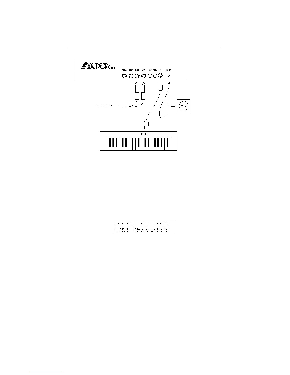
Audio Connections Connect the Modor NF-1 to an external amplifier or mixing device with an audio cable set via the Left and Right jack connectors on the backside of
the instrument. These are two mono 6mm jack sockets. The external amplifier or mixing device should be switched off before making this connection, and only be switched
on after the connection has been made to prevent damage to the equipment.
Don’t mistake the left- and right-audio connectors for the sustain- and volume pedal
connectors next to it. These don’t output audio signals, but bear a weak electrical
tension that might damage your audio equipment in some cases.
Midi Connection To play the instrument, it should also be connected to an external
keyboard or (computer) sequencer via a midi connection. Connect the midi-out output
of this external midi source to the midi-in connector on the backside of the Modor
NF-1.
Power Connection Finally, the Modor NF-1 has to receive power via the power connector. Connect the adaptor, and turn the volume knob (POW/VOL) on the upper left
corner of the front panel counterclockwise to get the instrument running. Theoretically,
any 9V DC-adaptor with 5W power (600mA) will be sufficient, but there are many DCadaptors around providing unstable or even plain wrong electrical tensions. Only use
the DC-adaptor delivered with the Modor NF-1 or refer to a specialised electronics
dealer. Damage to the instrument caused by using a wrong adaptor is excluded from
warranty.
1
Page 6
1.2. MENU NAVIGATION CHAPTER 1. GETTING STARTED . . .
Setting Midi Channel Finally the instrument has to be set to the right midi channel
such that the channel numbers of the external midi keyboard and the Modor NF-1
match with each other. Look up in the midi source device on which channel the midi
data for the Modor is being transmitted, so that we can set the same channel on both
devices.
You can find the Midi channel setting in the System Settings menu. Quickly push
the MENU button 6 times to access the System Settings menu (see §1.2 below for
more info on menu navigation). Next, select the system parameter ”Midi Channel” by
turning the SELECT data encoder, and set the correct MIDI receive channel with the
VALUE control [1-16]. Next press MENU again or press NO/DEST to leave the menu.
1.2 Menu navigation
The menu of the Modor NF-1 exists out of 9 menu items. When the MENU button is
hit you enter the menu, and the first menu item is shown on the upper display line. A
black dot starts running from right to left over the display. By pressing MENU again
before the dot reaches the left side of the screen, the next menu item is selected. If you
stop hitting MENU, after about 1 sec the black dot reaches the left side of the display,
and you enter the indicated menu. Following menus can be entered:
1. LOAD: Load a patch from internal memory
2. SAVE: Save a patch into the internal memory
3. NAME: Give your patch a name
4. PATCH INIT: Initialise the patch
2
Page 7
1.3. LOADING PATCHES CHAPTER 1. GETTING STARTED . . .
5. PARAMETER: To adapt a few sound parameters that have no dedicated knob on
the front panel
6. SYSTEM SETTINGS: To set some global system parameters
7. TONESCALE: Change the tuning of a patch with quarter tones up or down
8. FRMFRQ: Set the formant frequencies of the formant filter
9. MIDI DUMP: Dump a single patch or the complete patch memory using Midi
Sysex messages
Next, after entering a certain menu, data can be selected and altered using the SELECT encoder and VALUE control. Sometimes you need to validate your choice by
pressing the MENU button again, or you might need to approve or cancel your choice
by using SRC/YES or DEST/NO. While in the menu, on any moment you can press
DEST/NO to cancel and leave the menu.
1.3 Loading patches
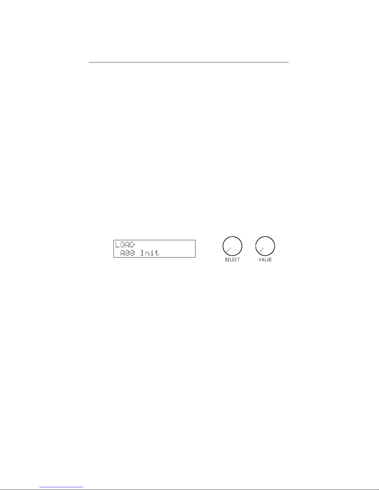
Hit the MENU button 1 time and wait 2 seconds to enter the LOAD menu. You should
see the following screen: On the first line you see ”LOAD” to indicate you are in
the LOAD menu, on the second line you see the active patchbank and -number and
patchname (of course, possibly with another patchnumber and patchname as in the
example below).
You can now scan through all the available patches in the Modor’s memory using
the SELECT and VALUE controls and YES/SRC-button. Press MENU again to select
and load a chosen patch, and confirm your choice with SRC/YES.
You can push DEST/NO at any time to cancel the load operation and return to the
patch you were using before. This way you can listen to the patches in the memory
without loosing your actual work, and compare your active patch to any patch in the
Modor NF-1’s memory.
1.4 Saving patches
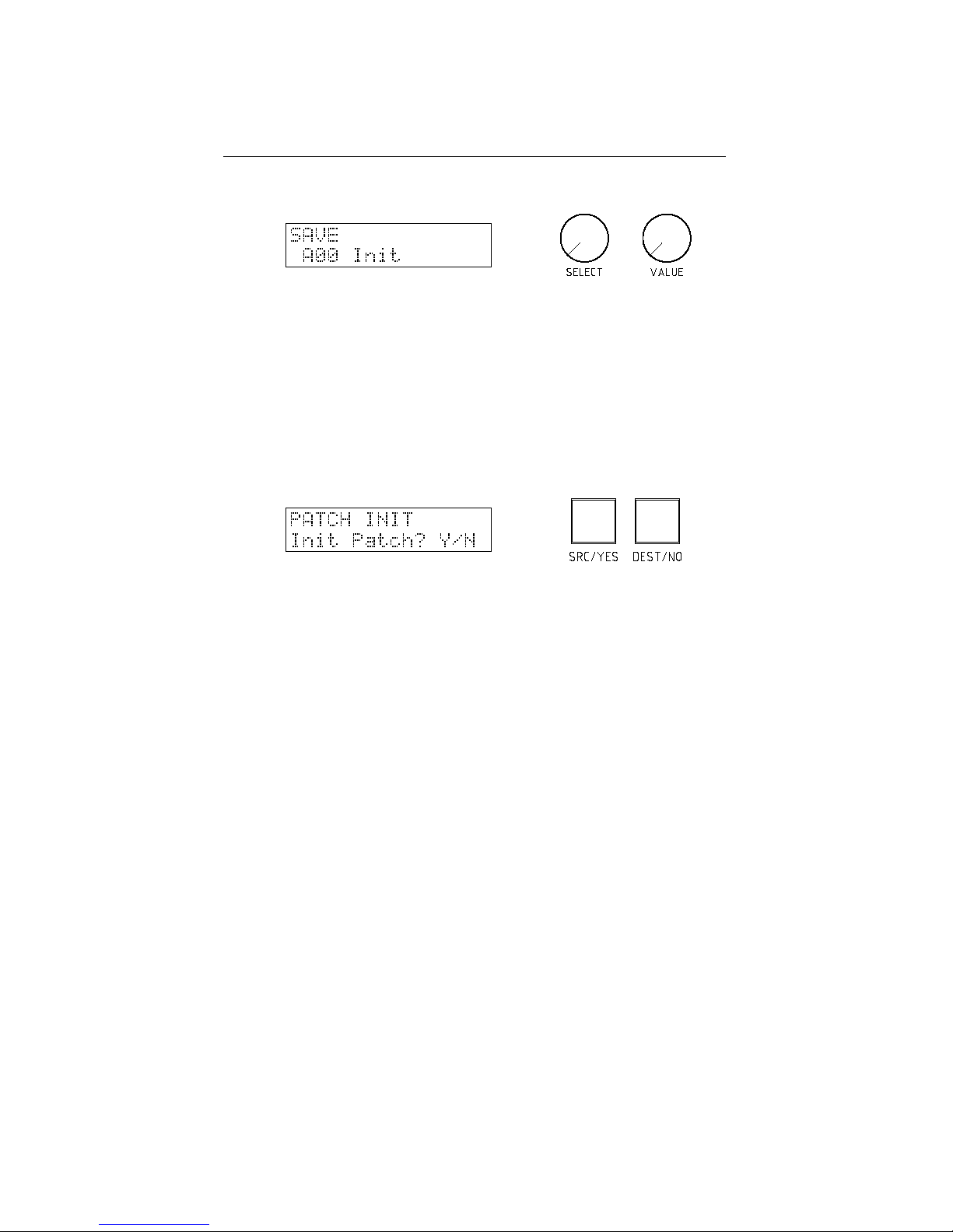
Saving patches goes identically to loading: press the MENU button twice within one
second to enter the SAVE menu. Select a slot in the memory using the SELECT and
VALUE controls and YES/SRC-button. This slot will be overwritten with the actual
patch and patchname if you now hit MENU again and confirm with SRC/YES.
When you play the keyboard during the save operation, you can hear the patch in
the Modor NF-1’s memory that’s about to be overwritten. This way you can check
which memory position can be overwritten before actually doing it.
Hitting DEST/NO at any time cancels the save operation and exits the menu of the
Modor NF-1.
3
Page 8
1.5. PATCH INITIALISATION CHAPTER 1. GETTING STARTED . . .
1.5 Patch initialisation
A last thing we explain in this ”Getting Started ...”-chapter is how to reinitialise the
actual patch. If you want to start building up a new patch completely from scratch, this
might be helpful. Quickly hit the MENU button four times to select the INITIALISEmenu and wait one second to select it (the black dot reaches the left side of the screen).
You now just get two options: Initialise or Cancel, make your choice with SRC/YES
or DEST/NO.
After initialisation, you have a patch consisting of a sawtooth wave on OSC1, the
other oscillators have their volumes at zero. The lowpass filter is fully opened and has
no resonance, and the amplifier envelope just has a gate-function. No effects are added
to the init sound.
4
Page 9

2
Overview
2.1 Structure of a patch
In this part, we consider how to create or adapt a patch. A ’patch’ might also be called
a ’sound’ or an ’instrument’, a patch is defined by a series of parameter settings that
determine on how the sound is generated, processed and transformed by the different
sections of the synthesizer. When you push a key on the keyboard, a sound is generated by the Oscillator section, filtered by the Filter section, amplified by the Amplifier
section and finally somehow altered by the Effects section. That is the general basic
structure of many so-called ’subtractive’ synthesizers, among which the Modor NF-1.
There is also a fifth section, the Modulation section. In this section a number of modulation signals is produced which can be used to alter or ’modulate’ the sound creation
parameters in the oscillator, filter, amplifier and effect sections. Each of these parts of
the synthesizer is further explained in the next chapters.
Oscillators
Filters
Amplifier
Effects
Modulation
The Modor synth contains:
• Oscillator section, chapter 3
– 3 oscillators with 10 waveforms
– a white noise source
– a ring modulator combining oscillators 2 & 3
• Filter section, chapter 4
– a classic LP/HP/BP/BS-filter with output drive
– a formant filter creating voice-like sounds
• Amplifier section, chapter 5
5
Page 10
2.2. FRONTPANEL OVERVIEW CHAPTER 2. OVERVIEW
– an amplifier with volume and pan settings (in PARAMETER menu) and
input drive
• Effects section, chapter 6
– a combfilter effects unit, creating chorus and flanger effects
– a delay effects unit
• Modulation section, chapter 7
– 3 low frequency oscillators (LFO’s)
– 4 envelope generators
– a random sample-and-hold (or noise) modulator and a lowpass-filtered ver-
sion of this
– velocity, aftertouch, expression pedal, ... and a number of other modulation
signals
– a modulation matrix with 7 freely assignable modulation ”wires” to route
any source to any destination
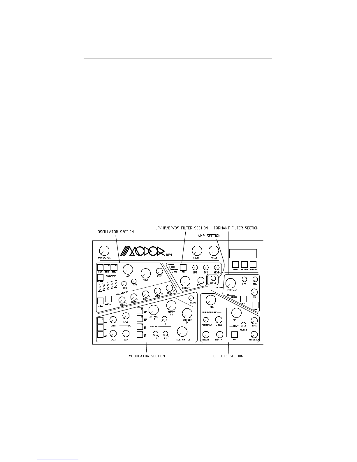
2.2 Frontpanel overview
You can find 43 rotary knobs and 20 pushbuttons on the frontpanel of the Modor NF-1,
grouped in the sections described above. Each of these sections get further detailing in
the next chapters.
In a short overview, following controls are found:
• Oscillator section, chapter 3
– OSC1, OSC2 and OSC3 selection buttons to select which oscillator is being
edited
6
Page 11

2.2. FRONTPANEL OVERVIEW CHAPTER 2. OVERVIEW
– WAVEFORM selection button, to set the selected oscillator’s waveform
– FM CARRIER and FM MODULATOR buttons, to select harmonics of the
ADD, FM and FBFM waveforms. These buttons have no function if the
selected oscillators have other waveforms than ADD, FM or FBFM.
– MOD control, to modificate the sound of the oscillator [0,127]. The effect
is depending on the active waveform. For example, it sets the pulse width
for the pulse wave.
– LFO control to set the amount of modulation of the MOD parameter by
LFO1 [-64,+63]. If no OSC is selected with the OSC1, OSC2 and OSC3
selection buttons, this control sets the amount of pitch modulation by an
LFO source.
– ENV control to set the amount of modulation of the MOD parameter by
the envelopes [-64,+63]. This is ENV1 for OSC1 MOD, ENV2 for OSC2
MOD and ENV3 for OSC3 MOD. If no OSC is selected with the OSC1,
OSC2 and OSC3 selection buttons, this control sets the amount of pitch
modulation by ENV1.
– TUNE and FINE controls to set the pitch of the selected oscillators. TUNE
sets the pitch in half tone steps [-32,+31], FINE ranges a half tone up or
down [-64,+63].
– OSC1, OSC2 and OSC3 oscillator volume controls to set the volume of
each oscillator [0,127].
– NOISE control to set the volume of white noise [0,127].
– RING control to set the volume of an additional ringmodulator acting on
oscillators 2&3 [0,127].
• Filter section, chapter 4
– Switchable LP/HP/BP/BS-filter
∗ TYPE button to select between hipass, lowpass, bandpass or notch
(bandstop) filters.
∗ CUTOFF control to set the filter’s cutoff frequency [0,127].
∗ LFO, ENV and KEYB controls to set the amount of modulation of the
cutoff frequency by LFO2, ENV2 and the keyboard position [-64,+63].
A setting of +32 of the KEYB control makes the filter frequency follow
the pitch 1:1.
∗ RES control to set the ”resonance” or ”filter quality” of the filter [0,127].
– FORMANT filter
∗ ROUTE button to choose between a parallel or serial configuration of
the LP/HP/BP/BS-filter and the formant filter
∗ VOWEL button to select 3 sets of formant frequencies (vowels)
∗ FORMANT control to morph between the 3 chosen vowels [0,127].
∗ LFO and ENV controls to set the amount of modulation of the formant
morph by LFO2 and ENV3 [-64,+63].
∗ MIX control to mix the formant filtered signal with other signals [0,127].
• Amplifier section, chapter 5
– DRIVE control to set the amount of distortion of the signal [0,127].
– the volume and pan controls are hidden in the parameter menu.
• Effects section, chapter 6
7
Page 12

2.2. FRONTPANEL OVERVIEW CHAPTER 2. OVERVIEW
– Comb filter effect unit, to mix the signal with a slightly delayed version of
itself (up to a few milliseconds). To make chorus, flanger and a number of
other effects.
∗ MIX control to mix between the dry signal and the altered signal
[0,127].
∗ SPEED control to set the delay modulation speed [0,127]
∗ DELAY control to set the delay modulation range [0,127]
∗ DEPTH control to set the delay modulation depth [0,127]
∗ FEEDBACK control to set the amount of feedback [-64,+63]
– a delay effects unit, to mix the signal with a delayed version of itself (up to
750 milliseconds) to create echo effects.
∗ MIX control to mix between the dry signal and the delayed signal
[0,127]
∗ TIME control to set the delay time [0,127]
∗ FEEDBACK control to set the feedback amount [0,127]
∗ FILTER control to activate a lowpassfilter on the delayed signal [0,127]
∗ SYNC button to syncronise the delays with a MIDI clock fed to the
Modor synth by an external sequencer.
• Modulation section, chapter 7
– GLIDE control to set the portamento time
– The envelope subsection, containing 4 3-stage envelopes. By setting T2=0
and L1=L2=127 this turns into a classic ADSR-envelope.
∗ ENV1, ENV2, ENV3 and ENV4 selection buttons to select the en-
velopes to edit.
∗ T1, T2, T3 and T4 time controls [0,127].
∗ L1, L2 and L3 level controls [0,127].
– The LFO subsection, containing 3 LFO’s and a random sample-and-hold
modulator. LFO3’s amplitude is set by the modwheel.
∗ SYNC button to syncronise LFO2 with a MIDI clock fed to the Modor
synth by an external sequencer.
∗ WAV1 and WAV2 buttons to set the waveforms of LFO1&2.
∗ LFO1, LFO2 and LFO3 speed controls [0,127].
∗ S&H random sample-and-hold speed control [0,127].
• Menu, chapter 8
– MENU button to enter the menu and select a submenu.
– SRC/YES button to set the modulation wire sources (§7.4) or to choose
”Yes” in certain menu’s.
– DEST/NO button to set the modulatione wire destinations (§7.4), to cancel
or to choose ”No” in certain menu’s.
– SELECT encoder and VALUE control to set the menu parameters, select a
patch to load, ...
8
Page 13
3
Oscillator section
3.1 Using the oscillators
The oscillators are the sources of the sound in a synth. There are three identical fully
independent oscillators in the Modor synth, oscillators 1, 2 & 3. Every oscillator has a
”modification” parameter (MOD), a pitch (TUNE and FINE) and 2 modulation controls
to set an amount of low frequency oscillator and/or an envelope modulation (LFO and
ENV). Further every oscillator has it’s harmonics settings for the ADD, FM and FBFM
waveforms.
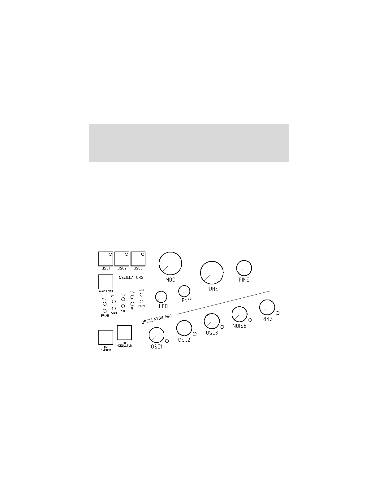
Selecting an oscillator: In the oscillator section on the frontpanel we find six pushbuttons and ten rotary knobs. Three of the pushbuttons are used to select which oscillator is being edited (OSC1, OSC2 and OSC3). The accompanying leds show which
oscillators (1,2 and/or 3) are selected, several oscillators can be selected at the same
time. If now any setting in the oscillator section is changed by turning a rotary button
are pushing waveform, this parameter is changed identically for all the selected oscillators. If for example, oscillators 1 and 3 are selected, and the ’coarse pitch’ knob is
set to +12, oscillator 1 and 3 are pitched up 12 semitones, while oscillator 2 stays at it’s
original pitch.
9
Page 14

3.2. OSCILLATOR WAVEFORMS CHAPTER 3. OSCILLATOR SECTION
Remark that these selection pushbuttons are not enabling or disabling the oscillators. This might be a little confusing when using the NF-1 for the first time. To enable
or disable an oscillator, just set its volume with the OSCILLATOR MIX controls.
Pitch modulation: When none of the three oscillators is selected (the leds in the
OSC1, OSC2 and OSC3 buttons are off) the LFO and ENV controls double up as pitch
modulation controls. By turning these controls an amount of LFO and ENV modulation
of the pitch is possible. ENV1 is the pitch envelope, the LFO source can be chosen in
the PARAMETER-menu (§8) between LS&H, S&H, LFO2 and LFO1.
Selecting a waveform: The first choice to make is the waveform of an oscillator.
There are 10 possible waveforms, treated in the following paragraphs. Every waveforms has a MOD (modify) parameter changing the oscillator’s output in a certain way,
for example the pulsewidth modulation on the Square PWM wave or the modulation
depth for FM waveforms.
Sawtooth PWM Pulse width modulation
Square PWM Pulse width modulation
Triangle PWM Pulse width modulation
Sync OSC Pitch of osc synced to base freq
Additive harmonics Harmonic separation
Sonar noise Filter Resonance
Wind noise Hipass filter
Arcade noise Hipass filter
Sinus FM FM amount
Sinus Feedback FM FM amount
This MOD-parameter can be modulated by LFO1 or an Envelope (ENV1, ENV2
and ENV3) using the rotary buttons MOD LFO and MOD ENV.
LFO1 → MOD OSC1, OSC2 en OSC3
ENV1 → MOD OSC1
ENV2 → MOD OSC2
ENV3 → MOD OSC3
The pitch of every oscillator can be adjusted independently using TUNE for semitone steps, and FINE for finer subdivisions in the semitones.
Oscillator mix Each of the three oscillators, the white noise source and the ring
modulator have their own level control in the OSCILLATOR MIX. By turning the
volume up, you enable a sound source. The accompanying led wil be lit if the volume
is set to a value bigger than zero.
3.2 Oscillator waveforms
3.2.1 Sawtooth PWM oscillator
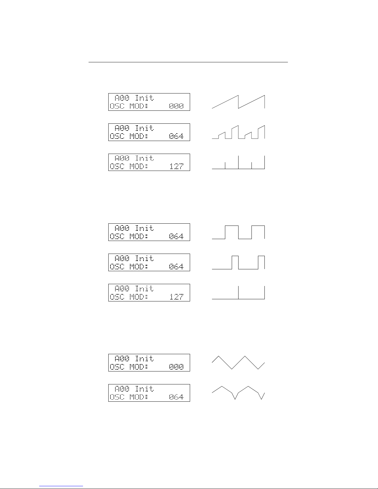
The sawtooth oscillator generates a sawtooth wave with a pulse width modulation as
in the figure below. With the modification parameter MOD at zero this gives a regular
10
Page 15
3.2. OSCILLATOR WAVEFORMS CHAPTER 3. OSCILLATOR SECTION
sawtooth waveform, turning up MOD creates ”holes” in the sawtooth that sound a bit
like the classic PWM on a square waveform.
3.2.2 Square PWM oscillator
The square oscillator generates a classic ”square” or ”pulse” waveform in which the
MOD parameter determines the duty cycle of the pulse. The sound of this waveform
gets more and more ”thin” with increasing MOD-parameter.
3.2.3 Triangle PWM oscillator
The triangle oscillator creates a classic triangle waveform, from whom the width of the
two halves of the waveform can be changed, as in the figure below. With higher MOD
setting, more and more overtones are added to the sound of the triangle wave.
11
Page 16
3.2. OSCILLATOR WAVEFORMS CHAPTER 3. OSCILLATOR SECTION
3.2.4 Sync oscillator
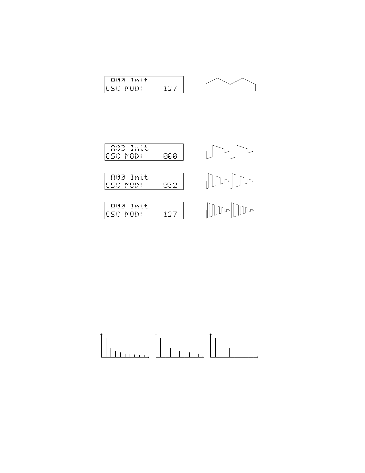
This oscillator creates a synced square wave with a decaying amplitude as shown in the
figures below. This sounds very much like a synced waveform found on many other
subtractive (virtual) analog synthesizers.
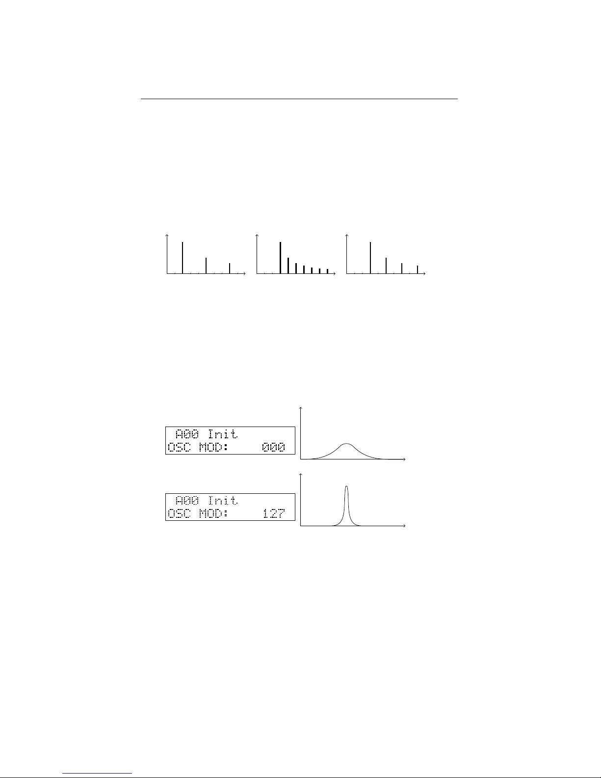
3.2.5 Additive harmonics oscillator
The additive harmonics waveform creates harmonic sine waves with frequencies in
multiples of the base frequency f. The modification parameter (MOD) determines the
distance N between consecutive sinewaves in multiples of f, N can be varied from 1 to
16.
N=1 : f, 2f, 3f, 4f, . ..(sawtooth)
N=2 : f, 3f, 5f, 7f, . ..(square wave)
N=3 : f, 4f, 7f, 10f, . ..
N=4 : f, 5f, 9f, 13f, . ..
and so on . . .
f
1 234
5 678
9
f
1 234
5 678
9
f
1 234
5 678
9
For N=1, we have a sound carrying all the harmonic overtones of f, which creates
a sawtooth wave, and for N=2 we have only the odd harmonics, which creates a square
wave. The only difference is that the number of harmonics that can be created in realtime is limited. On the lower part of the keyboard we hear that the ”additive sawtooth”
sounds more dull than the ”real sawtooth” of the SAW PWM oscillator.
12
Page 17
3.2. OSCILLATOR WAVEFORMS CHAPTER 3. OSCILLATOR SECTION
The additive harmonics oscillator still has another parameter: The FM-carrier parameter can be used to make the harmonic series start with another harmonic than f.
Juse the FM CARRIER button and the SELECT encoder to set another start harmonic.
For example:
S=2 en N=3 : 2f, 5f, 8f, 11f, . ..
S=3 en N=1 : 3f, 4f, 5f, 6f, . ..(a sawtooth with missing lower 2 harmonics)
S=3 en N=2 : 3f, 5f, 7f, 9f, . ..
f
1 234
5 678
9
f
1 234
5 678
9
f
1 234
5 678
9
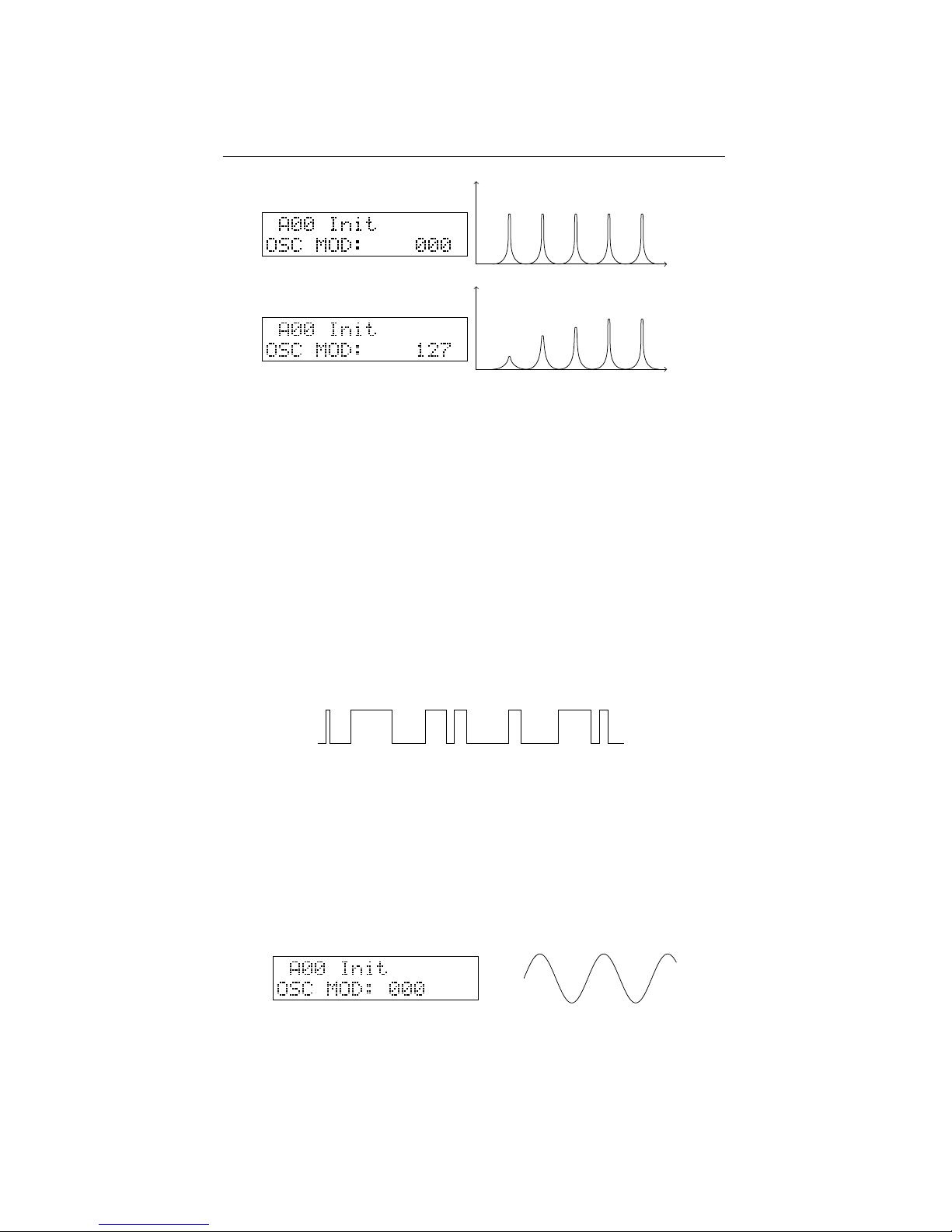
3.2.6 Sonar noise oscillator
This oscillator creates white noise filtered by a resonant bandpass-filter. The modification parameter controls the resonance of this filter. With MOD at zero, you get
bandpass filtered noise, the filter frequency depending on the played note’s pitch. With
increasing MOD, the sound gets more and more tonal, filtering out more and more
noise frequencies around the central peak frequency while enhancing frequencies close
to the peak. At maximum resonance this goes up to an almost pure sine wave of selfoscillation. A sound that resembles that of a U-boat sonar.
f
f
3.2.7 Wind noise oscillator
The Wind noise oscillator creates a tonal noise. A source of white noise is being filtered
to pronounce the note’s main frequency and it’s harmonics, creating a sound with noisy
harmonics, sounding not unlike a blow on a bottle or a panflute.
The modification parameter controls a 1-pole hipass filter. With MOD at zero, all
the noisy peak harmonics come through, increasing MOD gradually diminishes the
sometimes disturbing lower parts of this.
The wind noise oscillator sounds particularly well on higher notes, where it can
give the sounds of other oscillators a special bright character in a mix.
13
Page 18
3.2. OSCILLATOR WAVEFORMS CHAPTER 3. OSCILLATOR SECTION
f
f
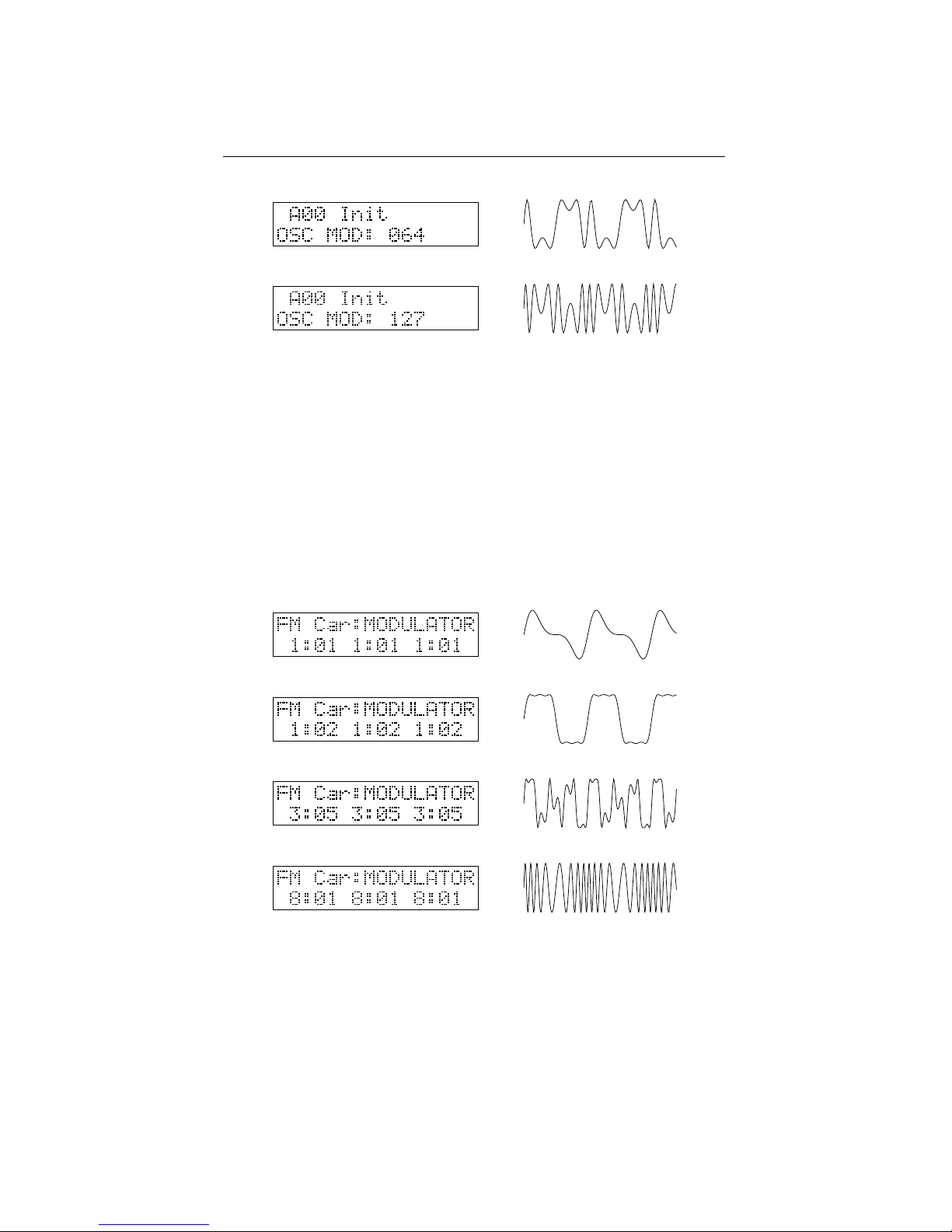
3.2.8 Arcade noise oscillator
This oscillator creates a type of hard noise with a certain tonal character. This type of
noise is remodelled after the noise creation algorithms present in early arcade video
game machines. It creates waves that look like pulses with randomly varying pulse
length.
In the age of early arcade video games the computer processors didn’t have the capacity to create digital sounds themselves. Instead, computer game consoles had dedicated sound/music chips under the hood, able of creating simple basic waveforms to
play melodies, and a rude noise generator for sound effects and ”percussion”. Some of
these chips had the ability to create this typical arcade noise, which had a ”frequency”
to simulate some kind of ”filtered noise”.
It might sound a bit unusual and unusable on its own in a synthesizer, but this
waveform can be used together with other oscillators to produce a noisy, tearing kind
of sound. The MOD-parameter controls a 1-pole hipass filter like on the wind noise
oscillator, eliminating the sometimes annoying lower noise frequencies.
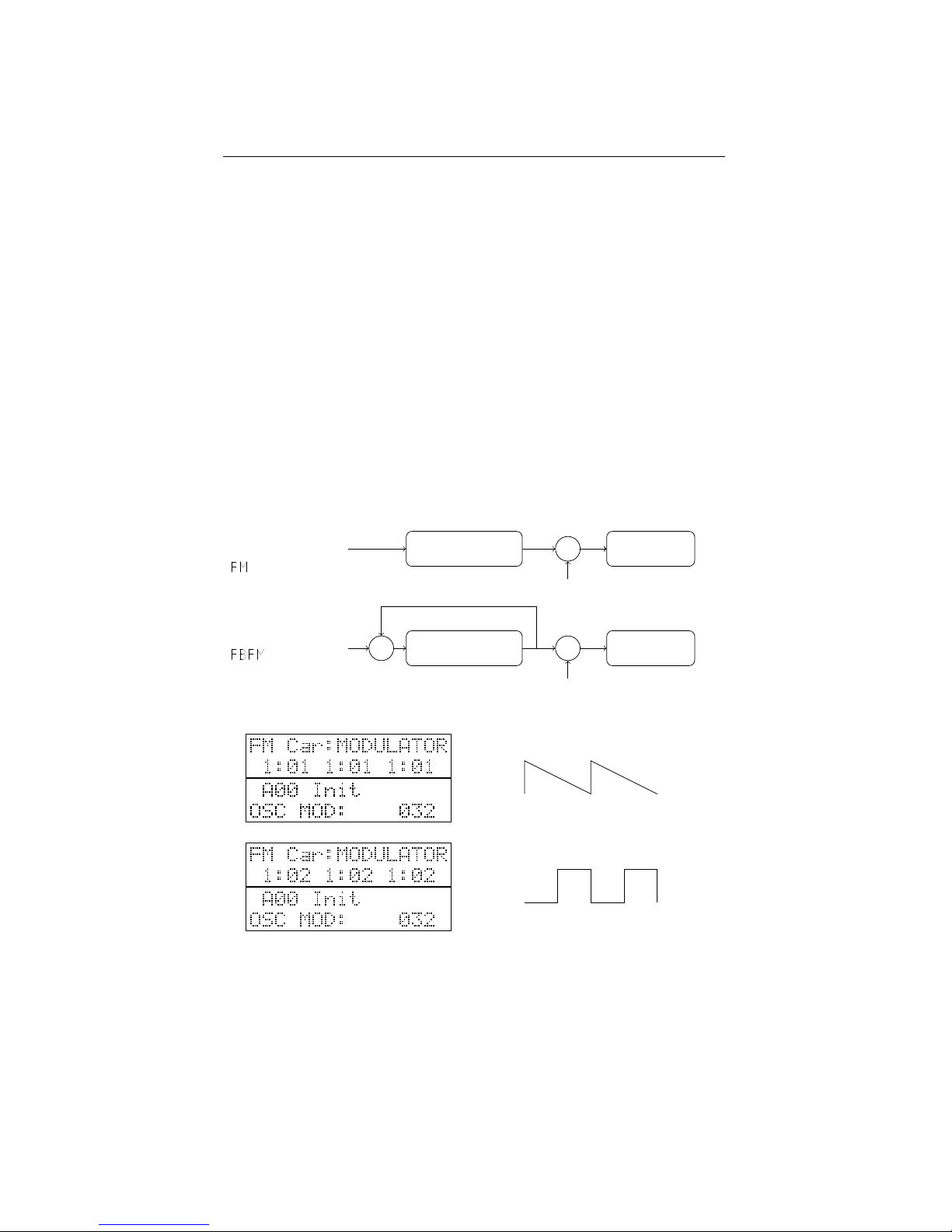
3.2.9 Sine FM oscillator
The sine FM oscillator creates a sine waveform called ”the carrier”, whose frequency
is being modulated by another sine waveform, ”the modulator”. You don’t hear the
modulator itself, but you hear its effect upon the carrier. The MOD-parameter in this
oscillator is the amount of this frequency modulation. With MOD set to zero (and no
modulation of MOD) you will hear a pure sine wave. When turning up the MODcontrol, you hear the sound changing, becoming more and more ”rich” with increasing
MOD. More and more harmonic overtones are added to the basic sine wave.
14
Page 19
3.2. OSCILLATOR WAVEFORMS CHAPTER 3. OSCILLATOR SECTION
The modulator’s frequency is in the audio range, just as the carrier frequency. You
won’t hear a sine wave going up and down in pitch, as you might expect when hearing
the term ”Frequency Modulation”, as if it’s frequency is modulated by an LFO. The
modulation process goes that fast that it changes the ”character” of the sound, not it’s
pitch. This is caused by the fact that also the modulator has an audio-scale frequency.
Upon initialisation of a patch, the frequency of the FM-oscillator’s modulator is equal
to the frequency of the carrier. It is said they have a frequency ratio of 1:1.
This ratio can be changed using the FM CARRIER and FM MODULATOR buttons. Both carrier and modulator can have their frequency changed to a multiple of the
base frequency. This makes it possible to work with frequency ratios of for example
2:1, 3:1, 3:2, 9:7, 8:5, ... . Each one of them resulting in a different timbre. Push the
FM CARRIER button to change the carrier’s harmonic, push the FM MODULATOR
button a second time for the same action on the modulator. You can try out any setting
with the carrier up to 8x and the modulator upto 16x the base frequency.
This kind of FM-synthesis is similar to the Yamaha FM-synthesizers of the 80’s
era. The use of sine waveforms keeps the amount of harmonics relatively low and
under control as opposed to modulating a sawtooth’s frequency with another sawtooth.
As such, it is somewhat different in character from the FM or ”cross-modulation” often
found on analog(-modelling) synths where one overtone-rich oscillator modulates the
frequency of another, creating even more overtones.
The carrier and modulator are generated independantly of what happens in other
15
Page 20
3.3. WHITE NOISE CHAPTER 3. OSCILLATOR SECTION
oscillators. This way, it gives the unique possibility of combining for example a glassy
80’s style-FM oscillator with classic analog or other waveforms. You don’t have to use
one oscillator to frequency-modulate another.
Some very typical 80’s FM-style patches can be made using an envelope to modulate the fm amount (MOD ENV). After initialising a patch, set the waveform to FM.
Choose a frequency ratio with FM MODULATOR, and set a certain (positive) amount
of envelope modulation on it using the ENV control of the oscillator. This gives you
a sound with a bright attack as found in vintage electric piano’s and toy instruments,
especialy with a higher modulator frequency.
3.2.10 Sine feedback FM oscillator
The sine feedback FM oscillator does something very similar to sine FM. But in this oscillator the modulator first modulates itself, before modulating the carrier. This results
in timbres with a lot more harmonics than with simple sine FM, sounding a lot brighter
than a sine FM oscillator having the same settings. For example: at a frequency ratio
1:1 and MOD set around +32, a sawtooth appears. Playing with the MOD-parameter,
the character can be varied to other ”sawtootish” sounds. The same thing happens with
ratio 2:1 where a square wave appears.
MODULATOR CARRIER
+
f
modulator
f
carrier
MODULATOR CARRIER
+ +
f
modulator
f
carrier
3.3 White noise
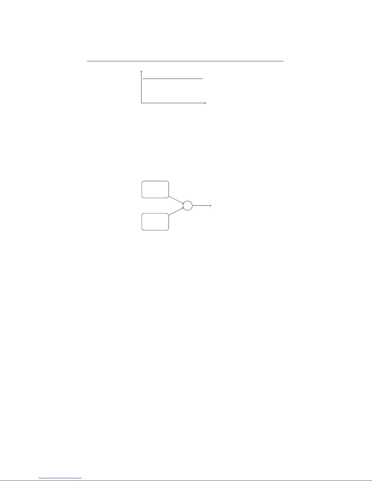
In the oscillator mix section on the front panel, an amount of white noise can be added
to the oscillator mix. White noise is a form of noise that has an equal amplitude on all
frequencies, it is completely atonal.
16
Page 21
3.4. RING MODULATOR CHAPTER 3. OSCILLATOR SECTION
f
3.4 Ring modulator
The ring modulator creates a multiplication of the signals from oscillator 2 and 3,
which results in a mix of sums and differences of the frequencies present in the source
oscillators. This mix of sums and differences gets most interesting when OSC2 and
OSC3 have a different tuning, which might induce inharmonic frequency peaks in the
sound.
OSC2
OSC3
∗
RING
17
Page 22
4
Filter section
4.1 LP/HP/BP/BS filter
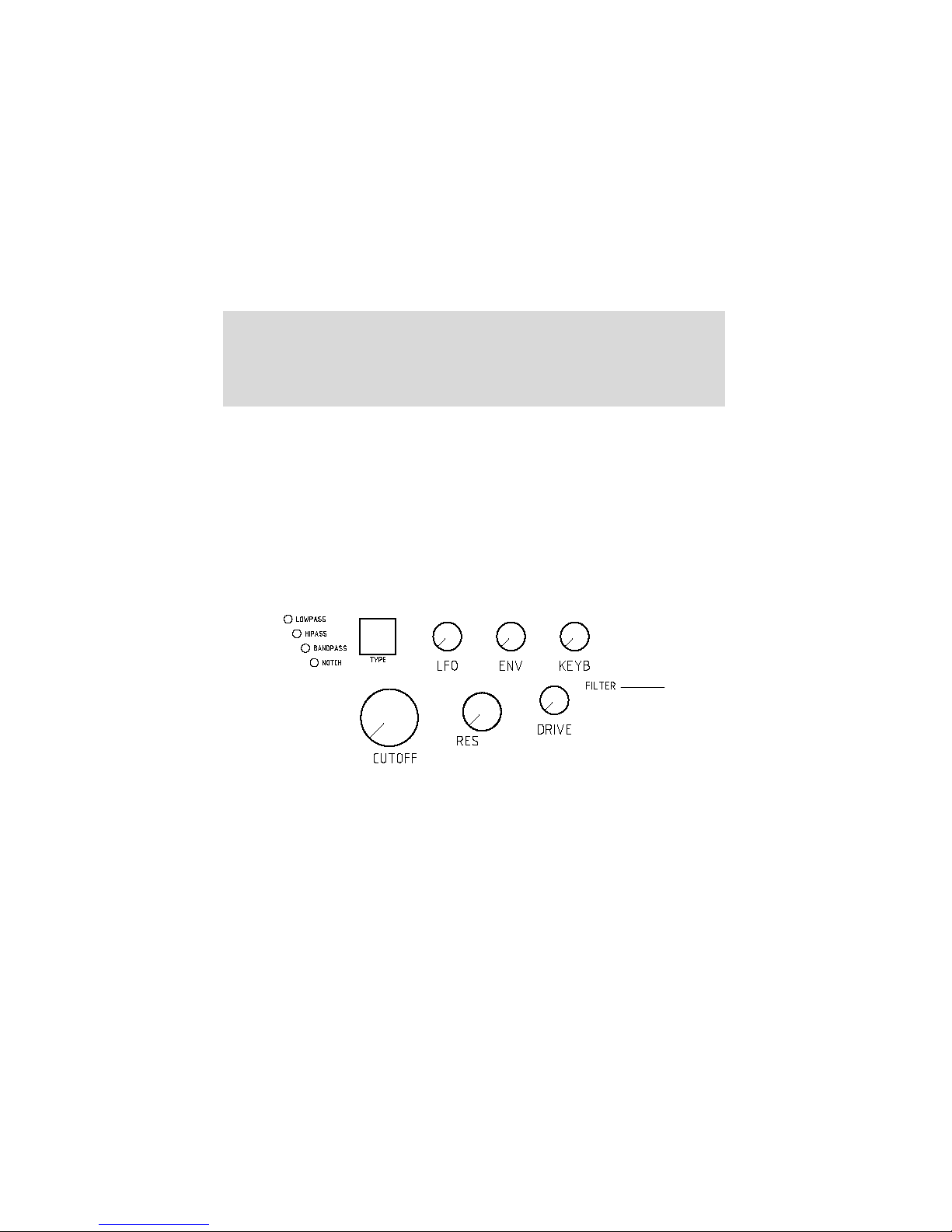
The main filter of the modorsynth is a selectable LP/HP/BP/BS resonant filter. You can
select it to be a lowpass (LP), highpass (HP), bandpass (BP) or bandstop (BS) filter. A
filter eliminates a certain part of the sound and and lets another part pass. In a lowpass
filter for example, the sound frequencies above a certain cutoff frequency are blocked,
while the frequencies below this cutoff frequency pass trough the filter.
Resonant means that it is possible, by turning up the RES control (filter Resonance) to enhance the frequencies close to the cutoff point. This results in a certain
sound character, quit typical to synthesizer sounds. With increasing resonance, these
frequencies are amplified more and more, upto selfoscillation, where the original sound
is oppressed by a cutoff frequency wave generated by the filter itself.
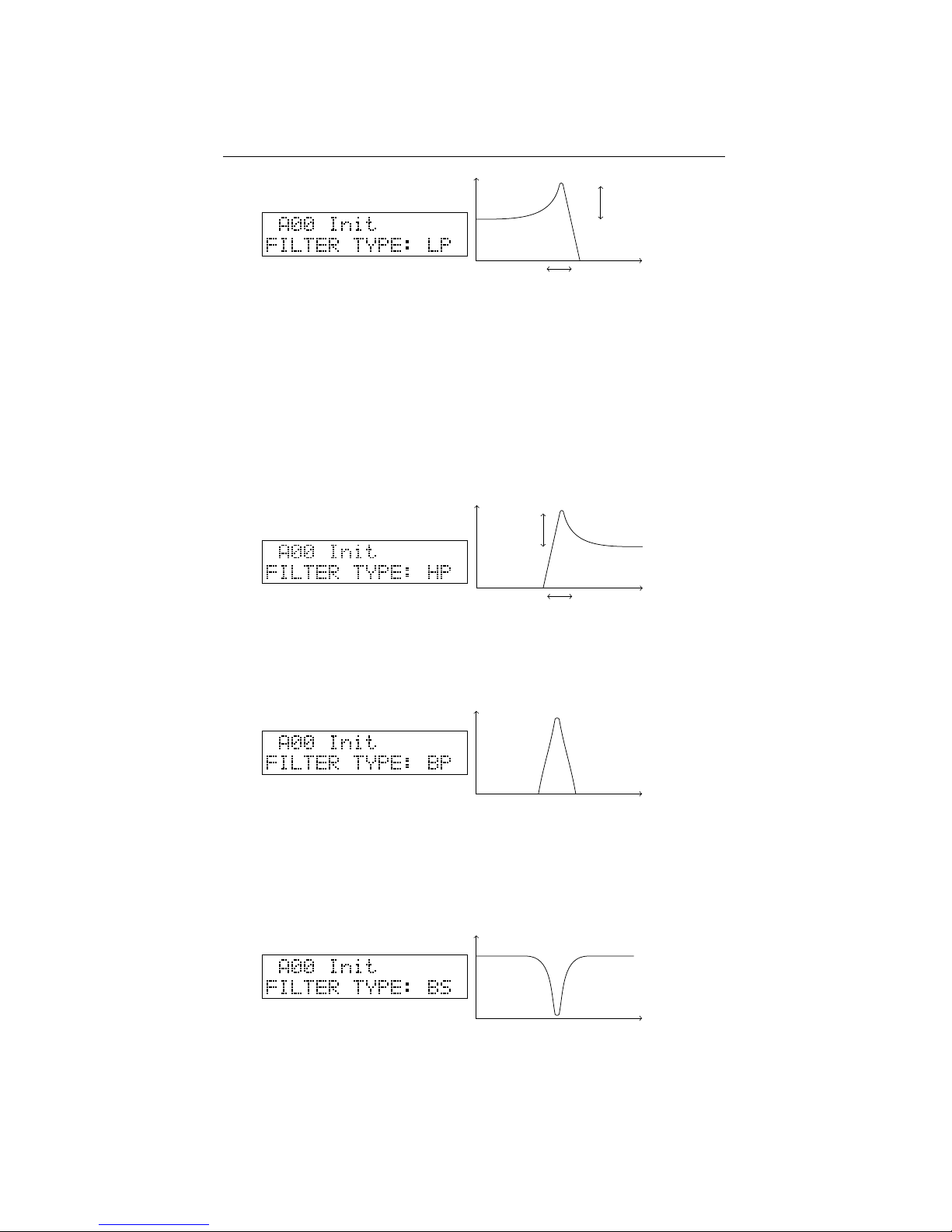
LP The lowpass filter blocks the higher frequencies and lets the lower frequencies
pass. This is the most popular, widely used filter in synthesizers. Especially in combination with a filter envelope (turn up the ENV-knob) and a high RES setting very
typical synthesizer sweeps are made. A faster envelope can alter a sound by giving it a
short, bright attack and a darker body.
18
Page 23
4.1. LP/HP/BP/BS FILTER CHAPTER 4. FILTER SECTION
cutoff
resonance
With the RES control at maximum [127] the filter goes into selfoscillation. This
means that a bright, sinusoidal wave is generated by the filter itself. Even without
input, with all oscillator volumes set to zero, the filter keeps producing sound. With the
KEYB control set at +32, you can even ”play the filter”. To do this however, it can be
necessary to feed a very little bit of sound or noise into the filter (ex. NOISE control at
very low level) to ”excitate” the filter.
HP The highpass filter reverses this behaviour, it passes the higher frequencies and
blocks the lower, resulting in bright sounds, or upto very thin sounds for high cutoff
settings. The resonance parameter again enhances the frequencies around the cutoff
frequency, upto selfoscillation.
cutoff
resonance
BP The bandpass filter only passes a certain amount of frequencies around the center,
cutting away the higher and the lower frequencies. Higher Q results in a smaller but
higher frequency peak, upto self oscillation.
BS The bandstop or notch filter is the reverse of the BP, it passes all frequencies,
except for a certain range around the central frequency. sweeping the cutoff-frequency
of the BS-filter results in a somewhat phaser-like sound. With increasing RES, this
stopband becomes smaller and smaller, until the effect of the filter is almost unhearable.
If the BS-filter seems to have no effect, decrease the resonance control.
19
Page 24
4.2. FORMANT FILTER CHAPTER 4. FILTER SECTION
Three standard modulation sources are hardwired to the filter’s cutoff frequency.
You can modulate the filter by a low frequency oscillator (LFO), an envelope (ENV)
and/or by the note’s base frequency (KEYB) using the three rotary knobs LFO/ENV/KEYB
of the filter section. The LFO that is wired to this knob is the global LFO2, of which
the speed and waveform can be set in the LFO section. The envelope wired to the filter
is ENV2. Modulating with the KEYB-knob means that the cutoff frequency will go
higher with increasing pitch, and lower with decreasing pitch, or reverse for a negative
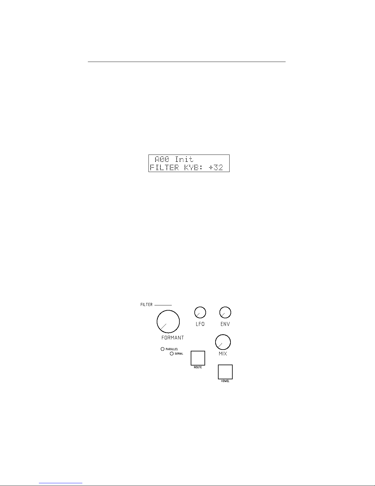
modulation amount. At a setting of +32 the cutoff frequencies exactly follows the note
frequency, necessary to keep the sound character unchanged with the pitch over the
whole keyboard.
Other modulations of the cutoff frequency or resonance, for example by velocity or
modwheel, is possible using the 7 freely assignable modulation lines (§7)
4.2 Formant filter
The formant filter is a very unique filter, never seen in any synthesizer hardware before.
It enhances so-called ”formants” or peak frequencies in the sound into specific combinations that make the filter sound like the vowels of the human voice. The formant filter
has 3 user-selectable vowels (or 3 sets of formants) behind the full-left, 12 o’clock and
full-right positions of the FORMANT control. After patch initialisation these vowels
are set at A (left) - E (center) - O (right). Turning the FORMANT control morphs the
sound between these three vowels.
The MIX parameter of the formant filter section mixes between a signal with and
without formant filtering. Turn it right to hear the effect of the formant filter. See also
§4.3
Formant frequencies The human brain recognises vowels as specific combinations
of peak frequencies. Depending on the movements one makes with it’s mouth and
throat, certain frequencies of the sound made by the vocal cords are emphasized, while
others are suppressed. For example, if a sound has peaks around 800Hz, 1200Hz and
20
Page 25
4.2. FORMANT FILTER CHAPTER 4. FILTER SECTION
2800Hz, it sounds like a ’A’. Ten presets of these peak frequency combinations are
programmed inside the Modor NF-1 and can be selected and placed in the three vowel
slots at left, center and right positions of the FORMANT-control.
Vowel Formant 1 Formant 2 Formant 3 Format 4
[Hz] [Hz] [Hz] [Hz]
A 808 1132 2848 3852
E 345 1195 2725 3852
O 412 808 2725 4845
I 264 2153 2973 3298
OE 194 945 2431 3298
EI 808 2100 2848 3852
EU 389 1132 1995 4373
AO 566 808 2431 4685
U 227 1602 1995 3500
UI 622 1293 2207 3780
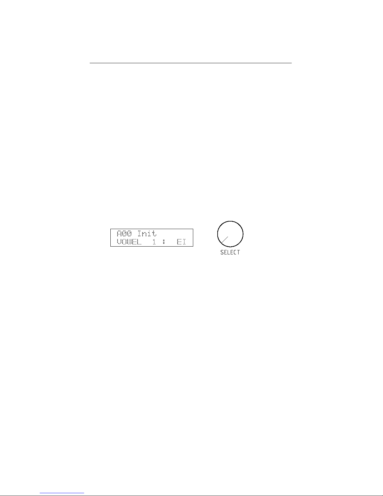
Push the VOWEL button to choose one of the three formant slots (1-2-3), and turn
the SELECT encoder to pick a vowel (A-E-O-I-OE-EI-EU-AO-U-UI). Any combination of 3 vowels can be made.
Apart from these presets, you can also alter these formant frequencies by yourself
in the FRMFRQ-menu to any combination of formants you want. This is explained
further in the menu reference, §8.
Formant mix After patch initialisation, the effect of the formant filter isn’t heard, the
filter seems inactive. This is because the formant mix is set to zero. The formant mix
parameter has to be set at a non-zero value, by turning the MIX control of the formant
filter to hear the effect of the filter. What the MIX control exactly does depends on
the filter configuration (§4.3), but it always mixes the output of the formant filter with
a sound without formants. As such you can choose how ”present” the formants are
in your sounds by turning the mix-knob, from a slightly vowelish character to a real
singing voice.
Formant filter input To clearly hear the effect of the formant filter, the input signal
needs to contain a broad range of frequencies. This way the formant peaks get clearly
audible. That means that the input signal needs to have many overtones, it works very
well with sawtooth-waves, much less on a triangle wave, and is barely noticeable on a
sine wave. This also means that the input signal needs to carry sufficient low frequency
components. In the upper octaves of the keyboard, the vowels get less pronounced,
while overtone-rich waveforms like a sawtooth or square wave in the lower octaves
make the formant filter very present.
21
Page 26
4.3. FILTER CONFIGURATION CHAPTER 4. FILTER SECTION
4.3 Filter configuration
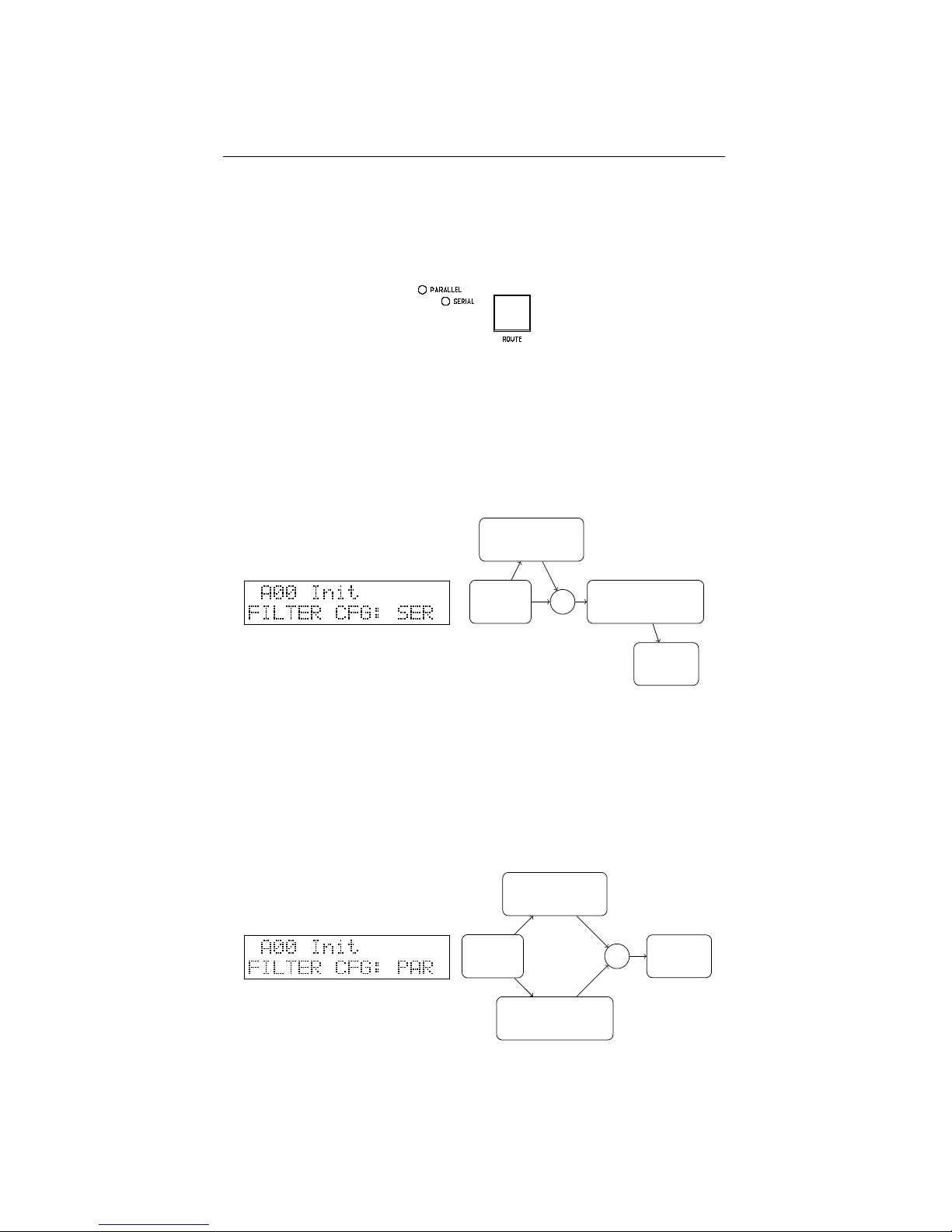
The filter configuration can be set to serial or parallel, using the ROUTE button in the
formant section. The corresponding leds on the frontpanel indicate which is the actual
configuration.
Serial In the serial configuration the sound of the oscillators is first led into the formant filter and then into the LP/HP/BP/BS-filter. The mix-parameter of the formant
filter forms a dry/wet-mix between the formant filter output and a dry, unfiltered signal. The result of this mix is then filtered by the LP/HP/BP/BS. In this configuration it
is for example possible to make a mix of a dry signal and a formant filtered signal, and
lead the result into a bandpassfilter to limit its frequency range. This way the output of
the formant filter can be further adapted using the LP/HP/BP/BS-filter.
OSC LP/HP/BP/BS
FORMANT
+
AMP
Parallel In the parallel configuration, the dry output of the oscillators is led to both
the formant filter and LP/HP/BP/BS-filter in parallel. The two output signals of the
two filters are then mixed together by the MIX-parameter. It is not possible to adapt
the output of the formant filter with a LP/HP/BP/BS-filter, the two filters are separated.
In this configuration it is for example possible to work with a formant-filtered sound,
and to add an amount of high frequencies by adding some hipass-filtered ”original”
signal. This way you can brighten up the formant filtered signal which can sound
somewhat dull due to the lack of higher harmonics in the filter result.
OSC
LP/HP/BP/BS
FORMANT
+
AMP
22
Page 27
5
Amplifier section
The amplifier section is quite straight-forward. First the output of the filter section can
be overdriven using the DRIVE-control, next it sets the volume and panning of the
sound, using the Amp envelope (ENV4) and the VOLUME and PAN settings in the
PARAMETER menu. It finally mixes all the different polyphonic notes together and
sends the result into the effects section. So, after the amplifier section, the sound of a
single note can not be altered any more. The effects sections treats the polyphonic mix
of all the separate notes in bulk.
Drive The output of the filter section is sent into a rather soft sounding overdrive
unit. A higher setting of DRIVE adds some extra overtone harmonics to the sound.
This can for example sound well with higher RES-settings by creating overtones of the
RES peak frequency.
Amplifier envelope The amplifier envelope ENV4 is always hard-wired to the VOLUME parameter and sets the volume evolution over time. The volume can also be
modulated using one of the 7 freely assignable modulation wires (see §7), for example
by an LFO to create a tremolo effect. The panning parameter determines the position
of a note in the stereo left-right image. It can be set in the PARAMETER-menu and
can also be modulated using any modulation source.
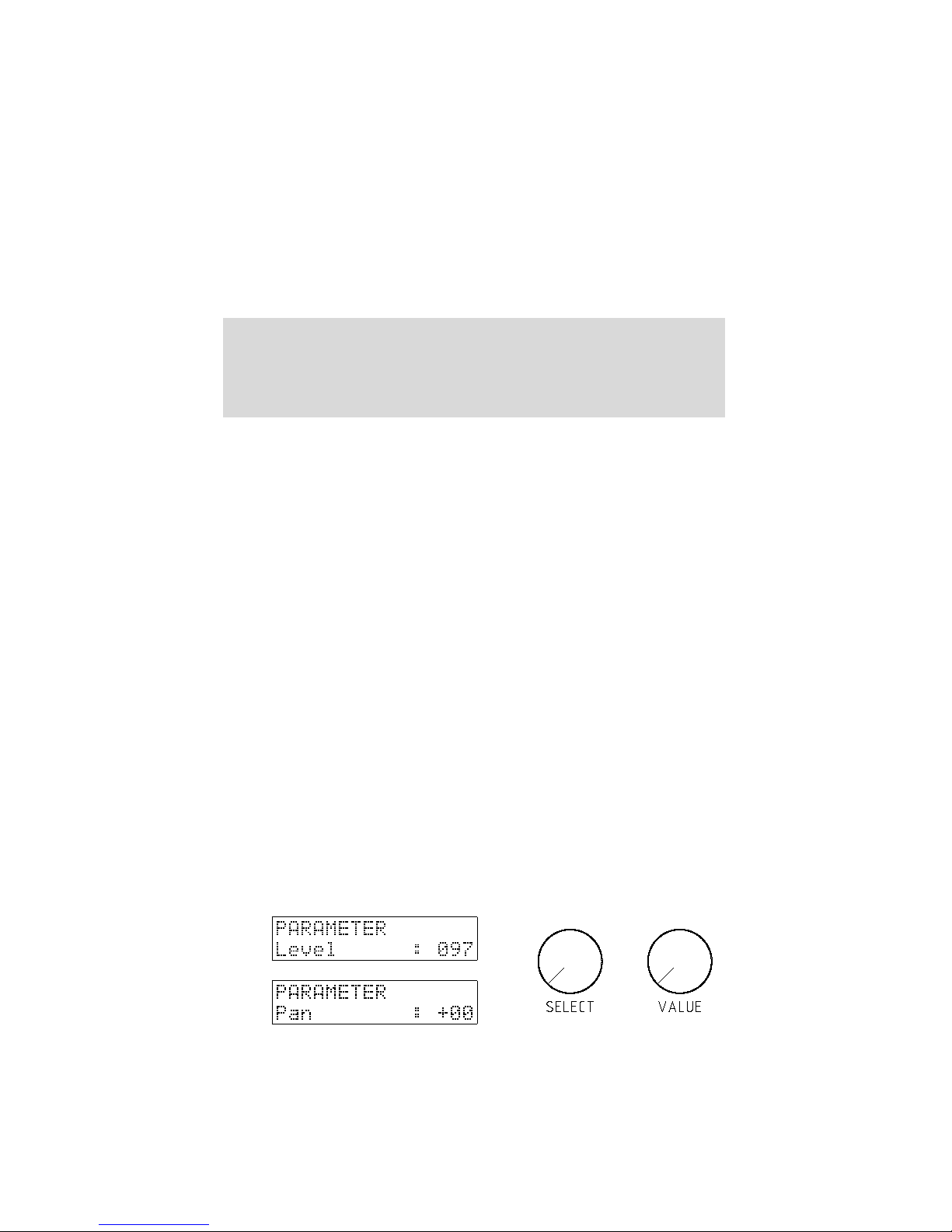
Level and Pan parameters To access the PARAMETER menu, push the MENU
button 5x shortly after each other. You can select a parameter by turning the SELECT
encoder, and change it using the VALUE-control.
23
Page 28
6
Effects section
6.1 Chorus/Flanger effect unit
Chorus, phaser and flanger effects are created by a so-called ’modulated comb filter’.
A comb filter takes a signal and adds a slightly delayed version of the same signal to
it, eventually with a feedback loop to repeat the delay multiple times. The delay time
stays in the order of maximally a few hundredths of a second. The delay time can be
modulated by a triangle LFO. The Modor NF-1 contains a comb filter effect unit in
which all the parameters can be set separately by a dedicated control, to offer maximal
freedom.
The comb filter is called that way because it creates a series of equally spaced peaks
and holes in the frequency spectrum of a signal, like the teeth of a comb. The space
between adjacent peaks is determined by the delay length, the depth of the peaks and
holes can be set with the feedback parameter, more feedback gives a more pronounced
comb filter effect.
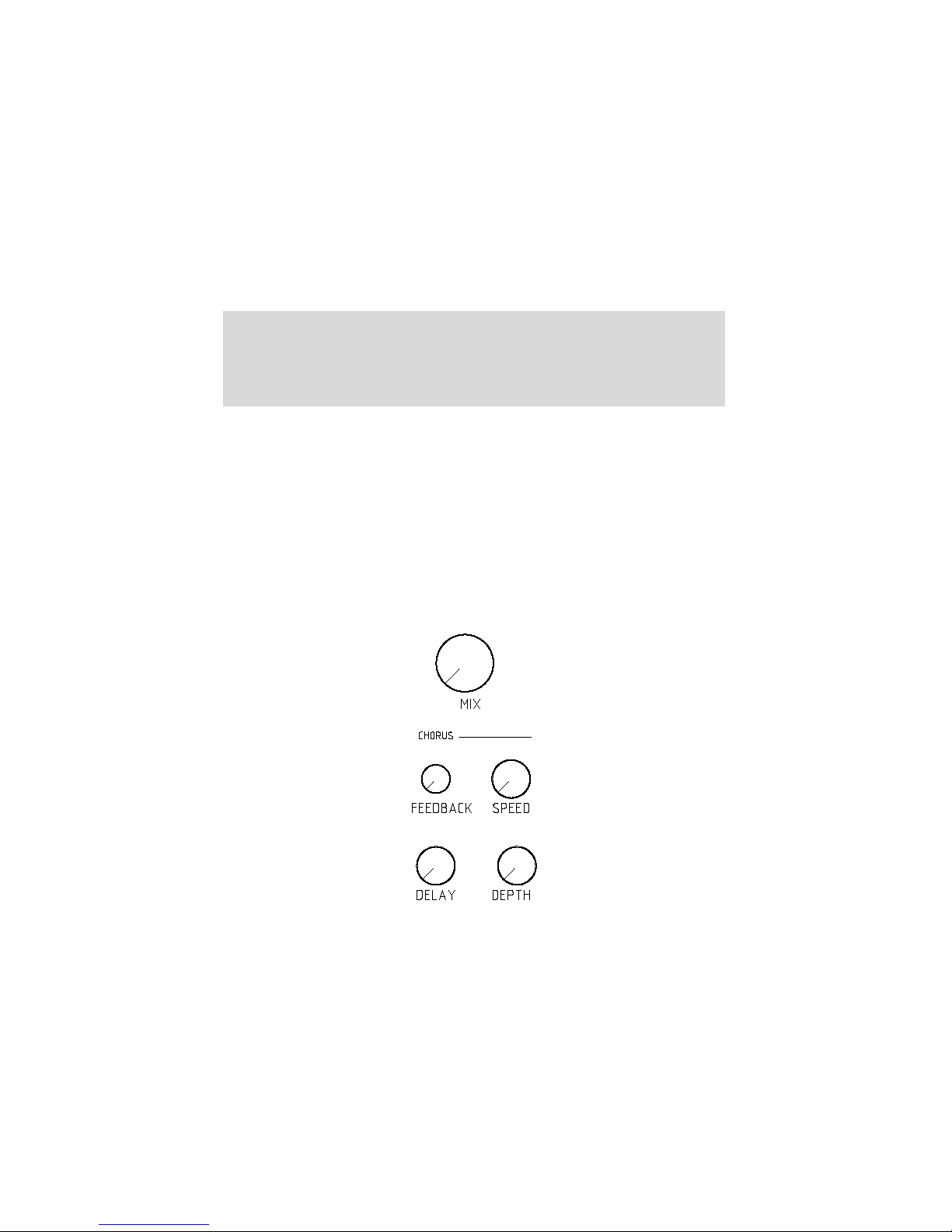
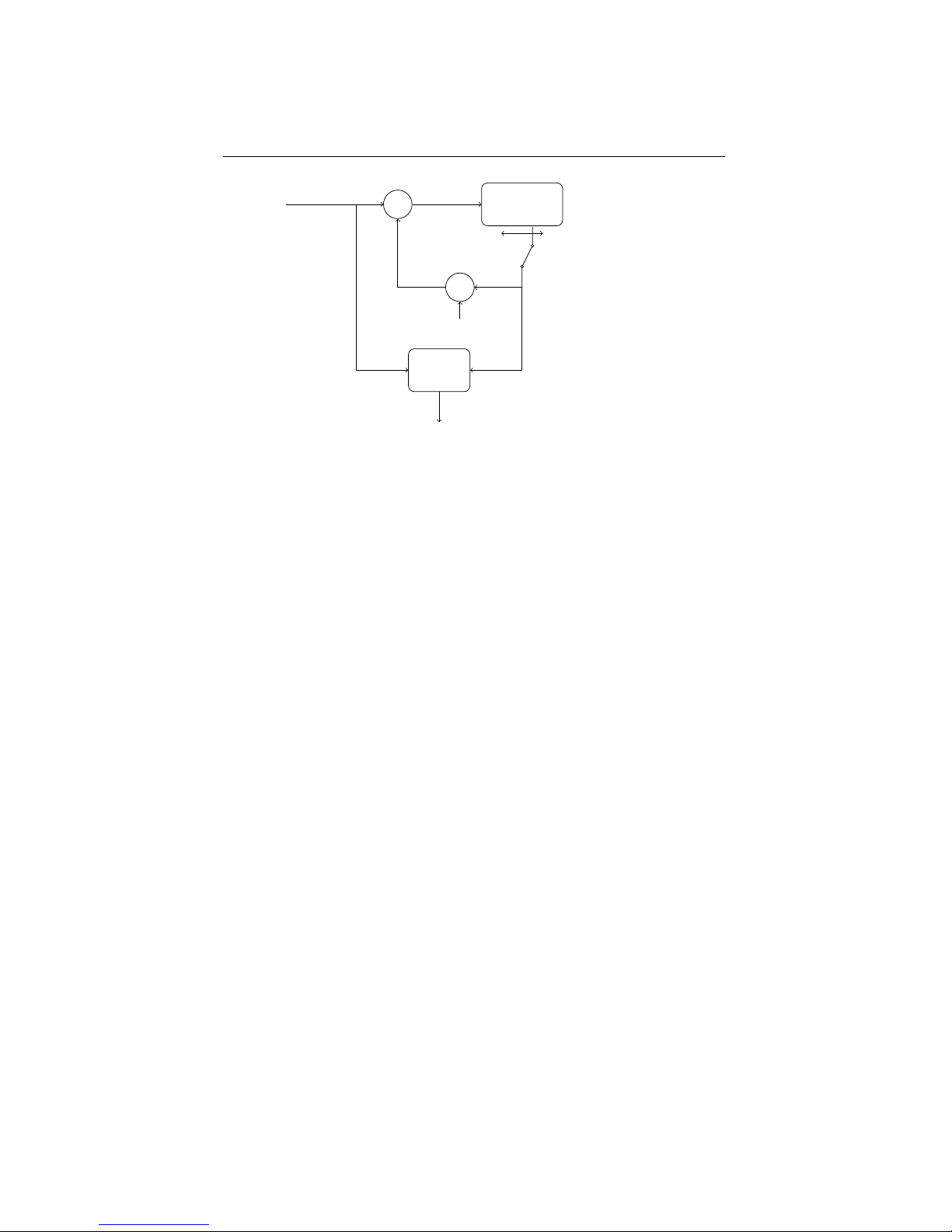
The parameters of the comb filter are:
24
Page 29
6.1. CHORUS/FLANGER EFFECT UNIT CHAPTER 6. EFFECTS SECTION
DELAY
+
×
FB
MIX
IN
OUT
Delay length modulation
Dry-wet mix This control sets the balance between the dry signal and the delayed
signal. This is set to zero to disable the comb filter effect unit, and often around halfway
to get a maximum chorus or flanger effect.
Delay length The delay length control sets the center around which the delay length
is modulated.
Delay length modulation depth The delay length gets continuously varied around
the central delay length by a separate triangle LFO. This control sets the modulation
depth, from zero (no modulation) upto maximum where the length is modulated between zero and 2x center length.
Delay length modulation speed This control sets the speed of the effect’s triangle
LFO.
Feedback With the feedback control, an amount of the comb filter’s delay is fed
back into the input, to enhance the filtering effect. This goes from a central zero (no
feedback) to a full negative or positive feedback where some very unmusical effect can
be created.
There are no effect presets, and every parameter can be set freely and independantly
to any value. So you might need some exercise to learn how to create a certain effect.
Following typical effects can be made using the combfilter unit:
• Vibrato: Fully turn the MIX-control right, such that only the delayed signal is
heard, and set the feedback to zero (center). Now play with the delay length
parameters to find a good vibrato.
• Chorus: A chorus effect tries to emulate multiple, slightly detuned voices, like
in a choir or ensemble. This is done by adding a delayed signal to the original
signal that is played alternately a little faster and a little slower than the original,
resulting in it’s pitch going up and down. To achieve a chorus effect, set the drywet mix around half way, creating a mix of the original with the delayed signal.
25
Page 30
6.2. DELAY EFFECT UNIT CHAPTER 6. EFFECTS SECTION
No or only very little feedback is added. Set the DELAY-control rather high, and
experiment with the SPEED- and DEPTH-control to receive a well-sounding
chorus
• Flanger: A typical flanger effect can be get with a quite high amount of positive
feedback and a very short delay line. Set the DELAY-control close to but not
equal to zero, turn up the FEEBACK-control close to maximum and set the MIX
somewhere halfway. Now play with the SPEED- and DEPTH-controls to get the
flanger effect you want.
• Pure comb filtering: When the modulation depth is set to zero the delay length
is not modulated. Set dry/wet around halfway to get a pure, static comb filtered
output.
• Feedback: With the modulation depth at zero, and the feedback fully positive or
negative, you get a heavy feedback signal almost like on an heavily distorted
feedbacking electrical guitar. Set the MIX-control somewhere halfway, and
DEPTH at zero. Turn the FEEDBACK-control fully up (positive feedback) or
down (negative feedback). The delay length control sets the feedback frequency.
Every parameter of the chorus/flanger effect unit can also be modulated using one
of the 7 free modulation ’wires’ (see §7.4), which creates possibilities for very special effects. You can for example modulate a feedback frequency with an envelope,
randomize your flanger speed or set the dry-wet mix with a foot pedal, or . . .
6.2 Delay effect unit
The delay effect unit creates echos in the sound, by adding a delayed version of itself
to the input signal. That is indeed quite identical to the comb filter effect unit, but
the delay lengths are much longer, such that separate echo’s can be heard instead of a
combfiltered signal. The delay lengths go up to around 750 milliseconds.
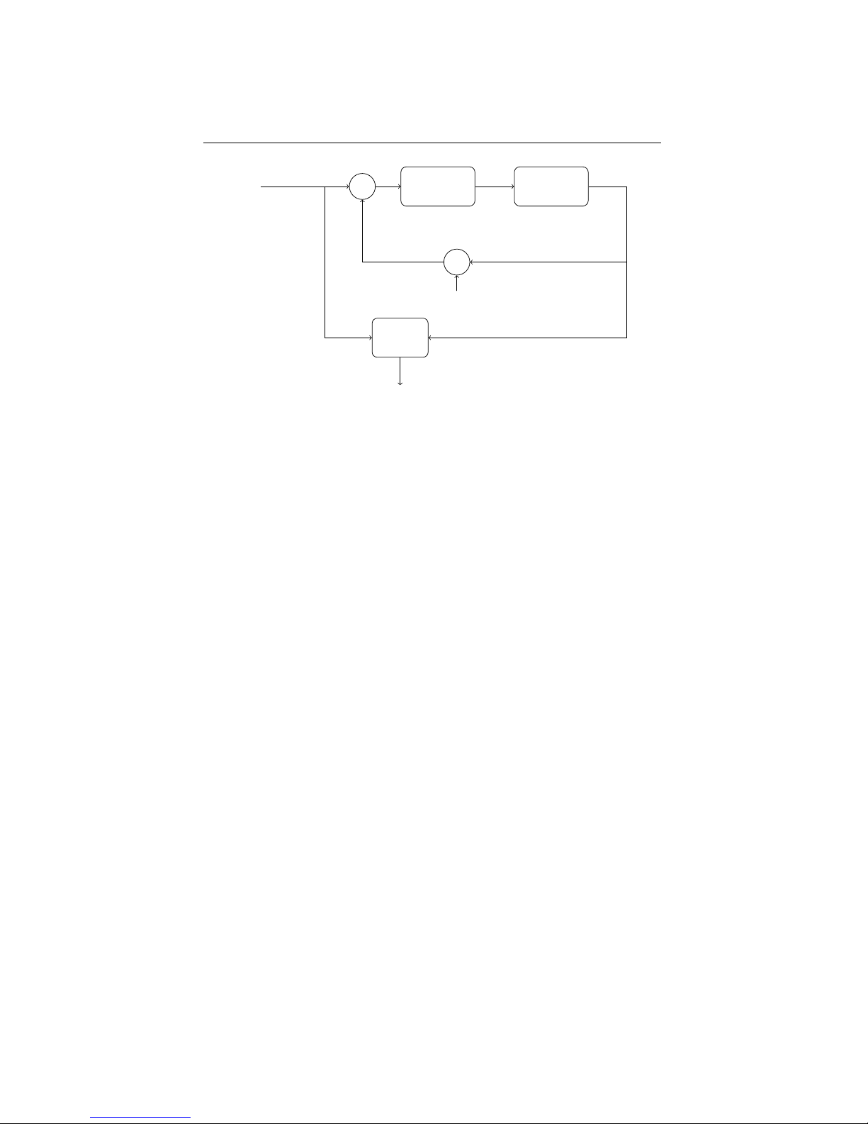
The Modor synth’s delay effect unit has a 1-pole lowpass filter in the delay line.
By setting it at maximum, the filter is inactive. Lowering this value applies a filtering
to the signal that gets more and more dull with each repeating echo. This sounds a bit
like older analog delay units.
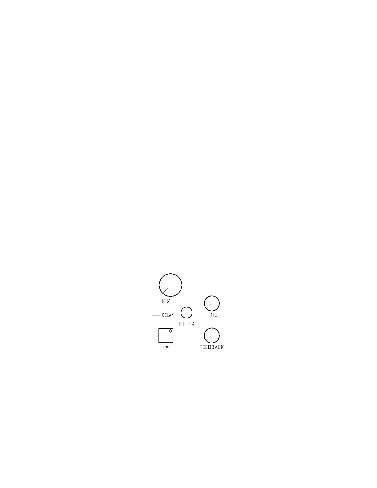
The parameters of the delay effect unit are:
Dry-wet mix This control sets the balance between the dry signal and the delayed
signal. This is set to zero to disable the delay effect unit.
26
Page 31
6.2. DELAY EFFECT UNIT CHAPTER 6. EFFECTS SECTION
DELAYFILTER
+
×
FB
MIX
IN
OUT
Time The delay length control sets the center around which the delay length is modulated.
Filter This control acts as a filter on the delay line. With the Filter control at maximum, the filter is fully open and no effect is heard.
Feedback The feedback sets the amount of delay output that is fed back into the
delay line. A feedback setting of zero blocks the feedback line, such that only a single
echo is heard. Setting it at maximum, the feedback gets high enough for the echo’s to
keep getting louder and louder. Mind your speakers and your ears!
Sync Button By pressing the Sync button, the delay syncronises to the midi clock
signals sent into the Modor synth by an external sequencer. The time control can now
be used to set the delay length from half notes to sixteenth notes.
Every parameter of the delay effect unit can also be modulated using one of the 7
free modulation ’wires’ (see §7.4).
27
Page 32
7
Modulation section
7.1 LFOs
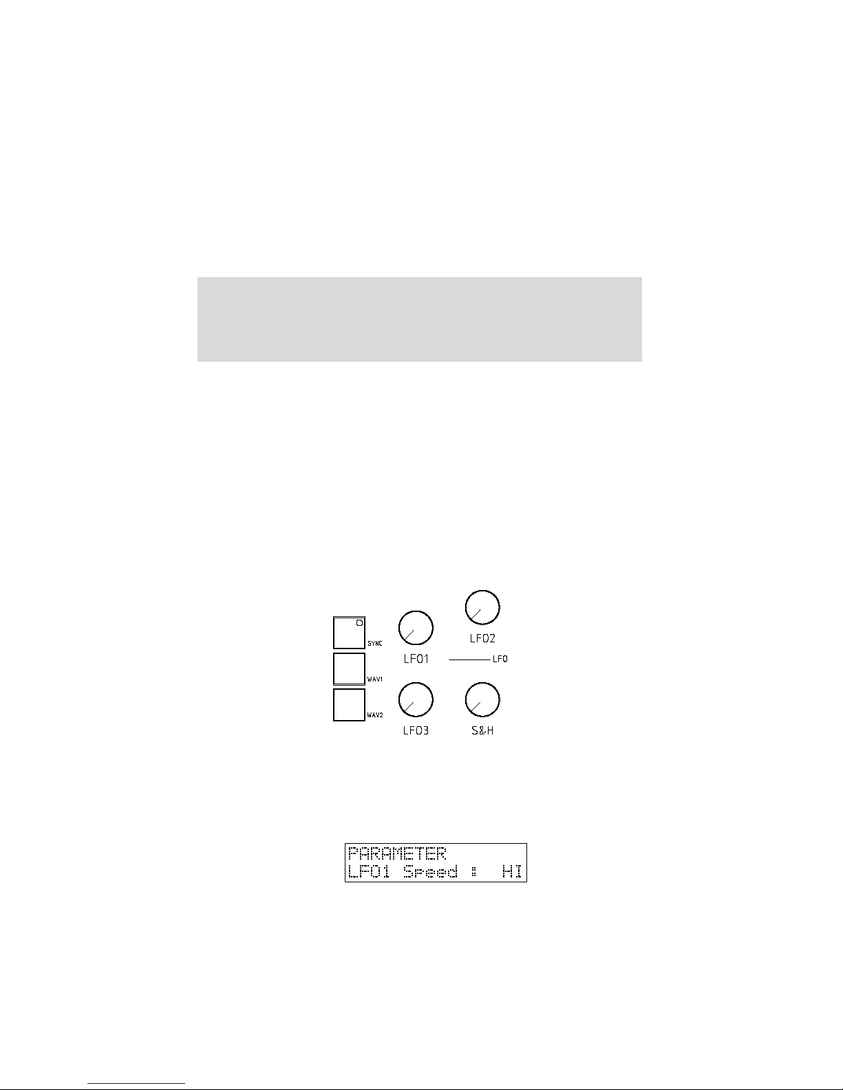
An LFO, or ”Low Frequency Oscillator” produces a cyclic modulation signal that can
be used to modulate a number of sound parameters. The frequency of the Modor
LFO’s can be varied between around 0,1Hz and 10Hz (or its cyclic period between 10
seconds and 100milliseconds). The speed of LFO1 can also be set alternatively to High
Speed mode in the PARAMETER-menu, in this mode the frequency can be varied from
around 2Hz to 200Hz.
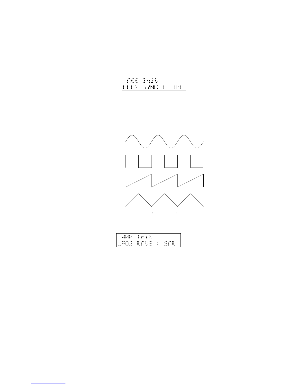
The waveform of LFO1 and LFO2 can be set to TRI (triangle), SAW (sawtooth),
SQU (square) and SIN (sinus) by pressing the WAV1 and WAV2 buttons.
• LFO1 is hardwired to the oscillator section to perform pulse width modulation
(PWM) and other modulations of the MOD parameter. LFO1 can be also be set
to High Speed mode, allowing its frequency to go up to a few hundreds of Hz.
LFO1 makes a ”separate” LFO for each active note, each played note starts its
own LFO1.
• LFO2 is hardwired to the filter section to modulate the cutoff frequency and the
formant morph. LFO2 is a global lfo, identical to all playing notes. LFO2 can
28
Page 33
7.2. SAMPLE&HOLD CHAPTER 7. MODULATION SECTION
be synced to an external MIDI clock, by hitting the SYNC button in the LFO
section.
• LFO3 is a global triangle LFO of which the amplitude depends on the setting of
the MODWHEEL, found next to the pitch bend wheel on most synth keyboards.
If the modwheel is down the amplitude of LFO3 is zero, with the modwheel fully
up LFO3’s amplitude is identical to the other LFO’s. If LFO3 seems to have no
effect, turn up the modwheel.
TRI
SAW
SQU
SIN
0,1s to 10s
7.2 Sample&Hold
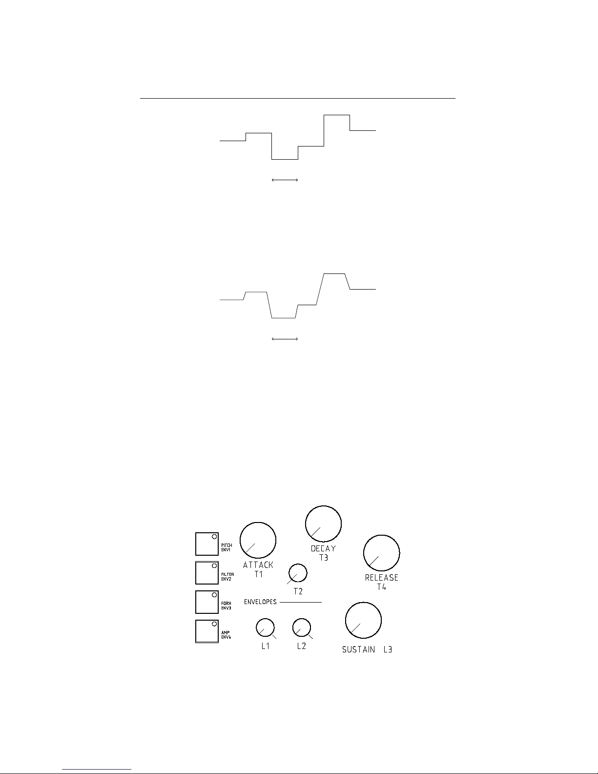
The Sample&Hold modulation signal is a signal that jumps to random values in a pace
set by the S&H speed control in the LFO-section. At lower speeds the separate steps
are clearly audible, while at high speeds the effect is quite identical to modulation using
a real noise source.
The sample&hold modulator is not hardwired to any parameter, but upon patch
initialisation it is selected as the source for pitch modulation (see also §7.5). When no
oscillator is selected (OSC1, 2 & 3 button leds are off), turning the LFO control in the
OSC section activates pitch modulation by a menu selectable source that is S&H after
patch initialisation.
29
Page 34
7.3. ENVELOPES CHAPTER 7. MODULATION SECTION
S&H speed
There is also a LS&H or lowpass sample&hold variant of this modulator that can
be chosen as modulation source. The LS&H makes a somewhat more fluent ”glide”
from one value to another, which can sometimes give beter effects in cases where too
sudden changes in a modulator can give unwanted effects.
S&H speed
7.3 Envelopes
The envelopes of the Modor NF-1 are more sophisticated than the classic ADSRenvelopes found on many synthesizers. The envelopes are 3 stage + release envelopes,
and therefore contain more controls than found on typical ADSR-envelopes.
There are four envelopes on the Modor NF-1. You select which envelopes you want
to edit using the ENV1 ... ENV4-buttons on the left side, much like the OSC-selection
buttons in the OSC section. The envelope which’ led is lit is being edited when you
turn one of the controls of the ENV-section.
30
Page 35
7.3. ENVELOPES CHAPTER 7. MODULATION SECTION
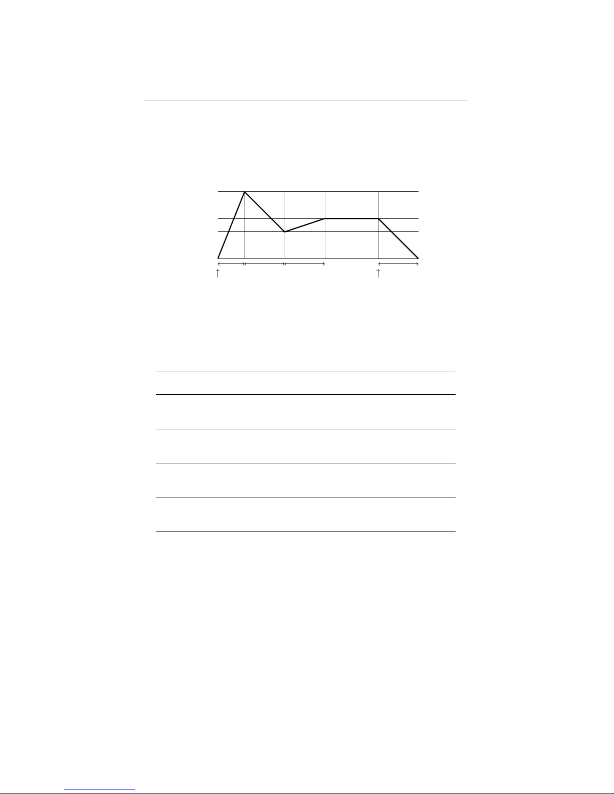
The envelope output level runs from zero over level L1 and level L2 to level L3
where it is held as long as the note is held on the keyboard. After the release of the
key it drops again to zero. The times to move from one level to another are set by the
time parameters T1 ...T4. T1 for 0→L1, T2 for L1→L2 and T3 for L2→L3. T4 is the
release speed at which an envelope shrinks back to zero after the key has been released.
L1
L2
L3
0
T1 T2
T3
T4
key pressed key released
There are 4 envelopes available on the Modor NF-1 (ENV1, ENV2, ENV3 and
ENV4). They are connected in hardware to the sound parameters in the table.
ENV1 ⇒ MOD OSC1
ENV1 alters the modification parameter of
OSC1 by an amount set using the MOD envelope control (MOD ENV OSC1)
ENV1 ⇒ PITCH
ENV1 can be set to alter the pitch using the
free modulation lines (§7.4)
ENV2 ⇒ MOD OSC2
ENV2 alters the modification parameter of
OSC2 by an amount set using the MOD envelope control (MOD ENV OSC2)
ENV2 ⇒ FILTER
ENV2 also alters the filter frequency by an
amount set using the filter envelope control.
(FILT ENV)
ENV3 ⇒ MOD OSC3
ENV3 alters the modification parameter of
OSC3 by an amount set using the MOD envelope control (MOD ENV OSC3)
ENV3 ⇒ FORMANT
ENV3 also alters the formant morph parameter
by an amount set using the formant envelope
control. (FORM ENV)
ENV4 ⇒ AMP
ENV4 determines the sound volume (AMP
ENV)
It is also possible to shape other sound parameters using the envelopes. There are
7 freely assignable modulation lines that can route the envelope to a large number of
modulatable parameters.
You can make a classic ADSR-envelope by setting L1 and L2 at maximum and T2
at zero. If you set these knobs, the other controls give you a classic ADSR-envelope.
• T1 = Attack
• L1 is set at maximum (127)
• T2 is set at minimum (0)
• L2 is set at maximum (127)
31
Page 36
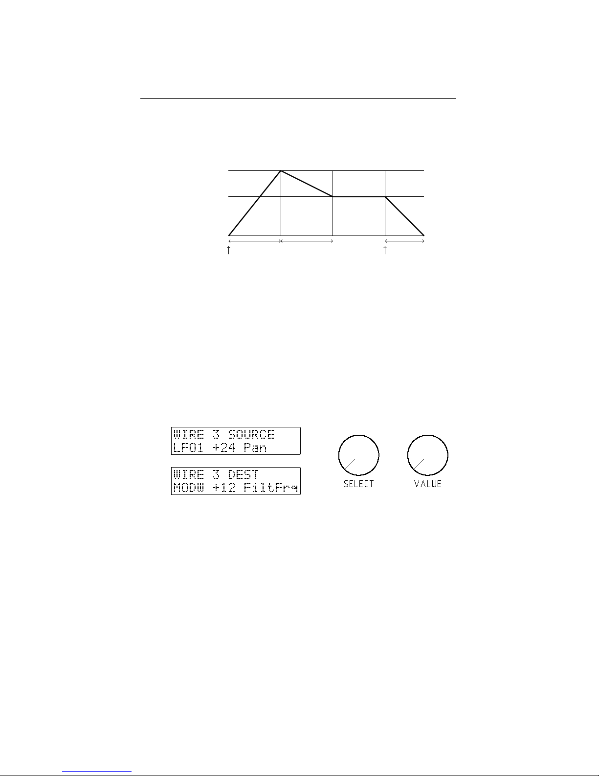
7.4. MODULATION MATRIX CHAPTER 7. MODULATION SECTION
• T3 = Decay
• L3 = Sustain
• T4 = Release
L1=L2=127
L3=S
0
T1=A
T2=0
T3=D
T4=R
key pressed key released
7.4 Modulation Matrix
The Modor NF-1 has a ”modulation matrix” of 7 freely assignable modulation lines that
can route some modulation source signals to a large number of destination parameters,
opening a near endless number of modulation possibilities.
To set up a modulation ”wire” push the source button (SRC/YES) a few times to
select WIRE 1, 2, ... 7, and turn the SELECT encoder to select a source signal. Next,
push the destination button (DEST/NO), turn the SELECT encoder to select a destination parameter and use the VALUE control to set a positive or negative modulation
amount.
Following source signals can be used:
• LFO1, 2 and 3
• ENV1, 2, 3 en 4
• VELO: Velocity. Gives a signal according to how hard a note’s key is hit. You
need a velocity sensitive keyboard for this.
• KEYB: A modulation signal dependent on a notes pitch. The higher the note,
the higher the modulation signal.
• MODW: The modulation wheel. This gives a high signal when the modulation
wheel is up, and a low signal when the wheel is down.
• PBND: The pitchbend signal gives a positive or negative signal depending on the
pitchbenders position relative to the center
• PEDL: the position of the volume pedal, that can be attached to the PEDAL-
connector at the backside. Also Midi control #007 sets this modulator.
32
Page 37

7.5. PITCH MODULATION CHAPTER 7. MODULATION SECTION
• RNDM: a random signal chosen at the start of a new note
• S&H: A modulation signal that changes to a new value on a regular interval, set
by the S&H speed control
• LS&H: LS&H is a lowpass filtered version of the S&H signal, it glides from one
level to another instead of suddenly jumping.
• AFTR: Aftertouch is a signal dependent on how hard a note key is pushed after
the initial attack. You need an aftertouch sensitive keyboard for this.
These modulation sources can be coupled to a long list of modulatable destination
parameters:
• Pitch, Modification (MOD) and Level of each of the 3 oscillators OSC1,2,3
• Pitch
• Level
• Pan
• Filter frequency and resonance
• Formant filter morph and formant mix
• Drive
• Ring modulator volume
• All Envelope parameters of every envelope
• LFO1 speed
• FM carrier and modulator harmonics
And also:
• LFO2, LFO3 and S&H speed
• Chorus/Flanger Mix, Speed, Delay and Depth controls
• Delay Mix, Time, Feedback and Filter controls
The second group are so-called ”global” parameters, and contain all of the effect
parameters and the lfo speed settings for all lfo’s except LFO1. The effect sections
work on the mix of all polyfonic notes together. Thus, for example if an ENV is chosen
as modulation source, which polyfonic note’s envelope is to be taken? In these cases,
it’s always the most recently played noted that delivers the modulation signal. The
same goes for the LFO2, LFO3 an S&H speeds as they are global modulation sources,
their phase and speed is always identical for all notes in the polyfony. LFO1 on the
contrary can show a different phase in different simultaneously played notes. Even the
LFO1 speed can be different for every note.
7.5 Pitch Modulation
The front panel of the Modor NF-1 doesn’t seem to show any pitch modulation controls. But they’re not far away. If all three oscillator selection buttons (OSC1, OSC2
and OSC3) are deselected, the LFO and ENV controls in the oscillator section double
up as pitch modulation controls. Other pitch modulation lines are preset in the free
modulation lines after patch initialisation.
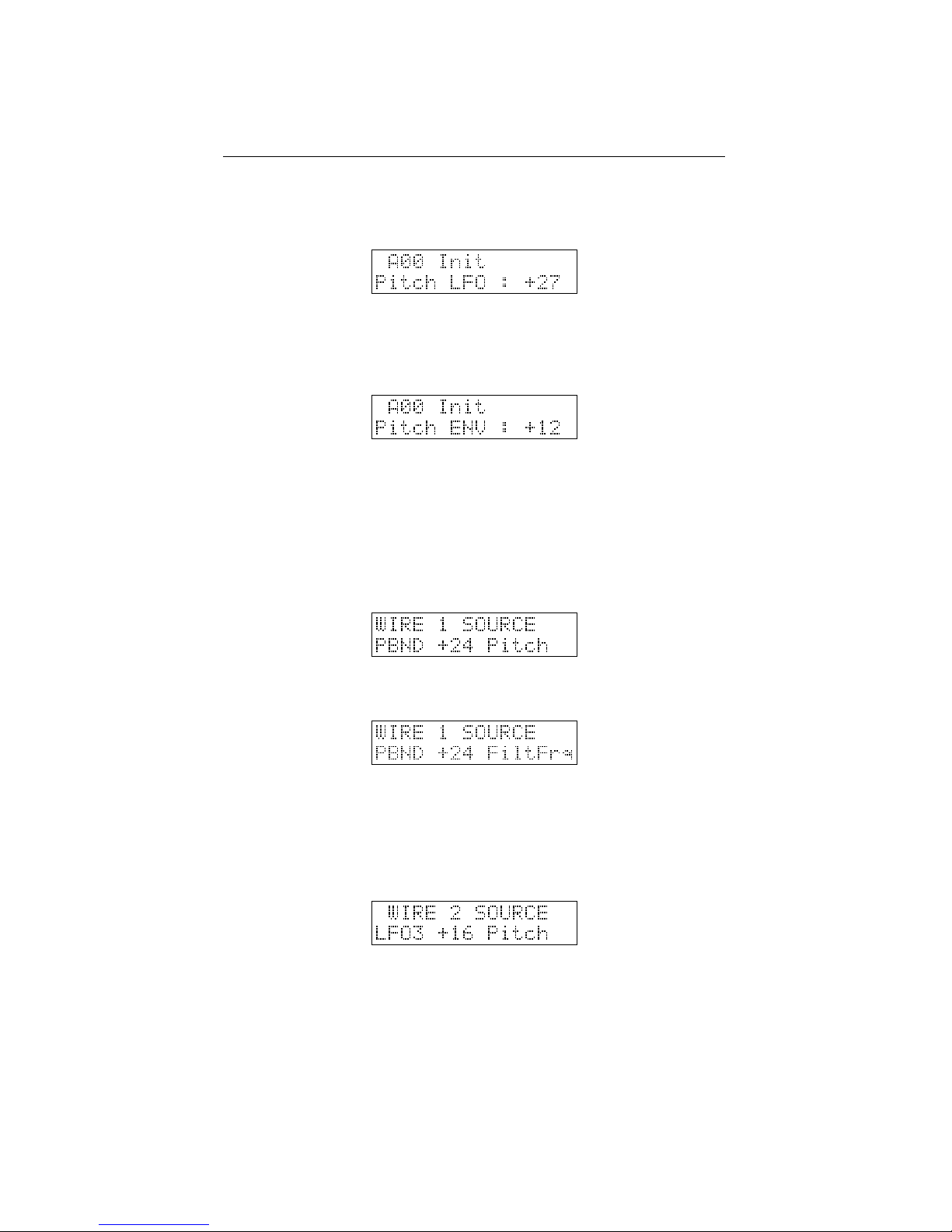
Pitch LFO When OSC1, OSC2 and OSC3 buttons are disabled, you can turn the
LFO-control in the OSC section to get an amount of LFO or S&H pitch modulation.
33
Page 38
7.6. AMPLITUDE MODULATION CHAPTER 7. MODULATION SECTION
After patch initialisation, the pitch LFO source is set to ”S&H”. This can be adapted
in the parameter menu (see §8), where you can select LFO1, LFO2, S&H and LS&H
as pitch LFO source.
Pitch Envelope Also, there is no dedicated pitch envelope control on the front panel
of the Modor NF-1, but with OSC1, OSC2 and OSC3 buttons disabled you can use the
ENV-control of the OSC section to set an amount of pitch modulation by ENV1.
Portamento Using the GLIDE-control on the frontpanel, a certain amount of ’glide’
or ’portamento’ is activated. The note pitches seem to glide to one another, with a
speed controlled by the GLIDE-control.
Pitch Bend Upon patch initialisation, the first of the seven free modulation wires
(§7.4) is used to set the pitchbend range. A setting of +24 makes this range 1 octave
up/down.
But of course you can alter this settings, to make the pitch bend alter the filter
frequency instead of the pitch for example.
Modwheel vibrato LFO3 can be used to create the very typical vibrato effect using
the modwheel, as found on almost any synthesizer. After patch initialisation, LFO3
is routed a certain amount to pitch. When you turn up the modwheel of your master
keyboard you’ll here the pitch going up and down. The LFO3-control sets the speed,
the modwheel sets the intensity of this effect (actually, it sets the amplitude of LFO3).
7.6 Amplitude Modulation
Apart from the pitch modulations, there are also a number of popular basic amplitude
modulations preset in the free modulation lines (§7.4).
34
Page 39
7.7. OTHER POPULAR MODULATIONSCHAPTER 7. MODULATION SECTION
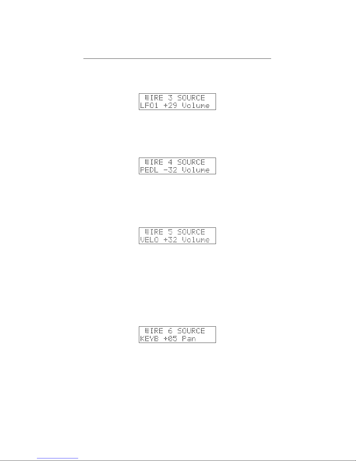
Tremolo After patch initialisation, the third modulation wire is preset as a tremolo
effect. Push the Src/Yes or Dst/No button 3 times and set the tremolo amount with the
VALUE-control.
Volume pedal The fourth modulation wire is preset at initialisation to use a foot pedal
to control the volume. The PEDL modulation source is controlled by a pedal connected
to the pedal connector on the backside, or using Midi control change CTRL#007 from
your sequencer or master keyboard.
Velocity The fifth modulation wire is preset to achieve a velocity effect. The harder
you play the notes on the keyboard, the higher the volume if you set a positive amount
on this modulation wire. It might be necessary to lower the Volume parameter in the
PARAMETER menu a bit to have more effect. Your master MIDI keyboard needs to
be velocity sensitive for this.
It is also very rewarding to route a certain amount of velocity to other mod destinations. This really livens up the sound of your synthesizer when playing on a keyboard,
making every note sound a bit different and more expressive.
7.7 Other popular modulations
Stereo panning It can be interesting to modulate the stereo position of a sound. For
example by the KEYB-modulator to put the higher notes a bit more to the right, and
the lower a bit to the left. Or route a small amount of the RNDM-modulator to the
Pan-parameter, to give every note a bit different position in the stereo image . . .
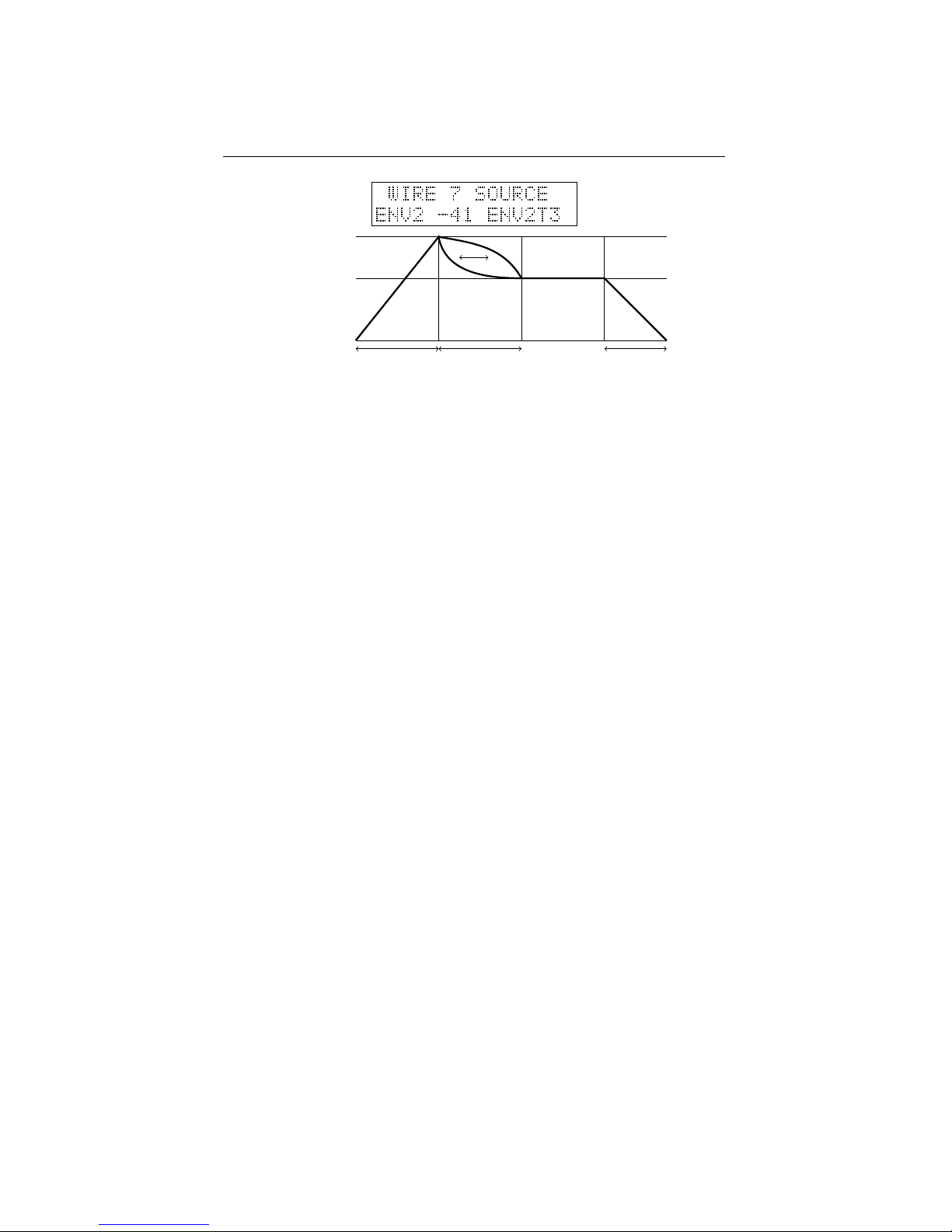
ENV decay curve Envelope self-modulation. A popular trick among professionals.
You can modulate the decay (or attack) of an envelope by the envelope itself. This
alters the decay (attack) curve, which often proves to be interesting, for example in
fast FM envelopes. Route the envelope (source) to the decayparameter of that same
envelope and set an amount of modulation...
35
Page 40
7.7. OTHER POPULAR MODULATIONSCHAPTER 7. MODULATION SECTION
L1=L2
L3=S
0
T1=A
T2=0
T3=D
T4=R
And so on . . . And of course, a lot more modulation wires can be set up! How about
an envelope that alters the oscillator mix? The aftertouch opening and closing your
filter? A random LFO speed? A pedal to set your envelopes attack speed? A velocity
sensitive formant filter? . . . Litteraly hundreds of combinations, only limited by your
imagination!
36
Page 41

8
Menu Reference
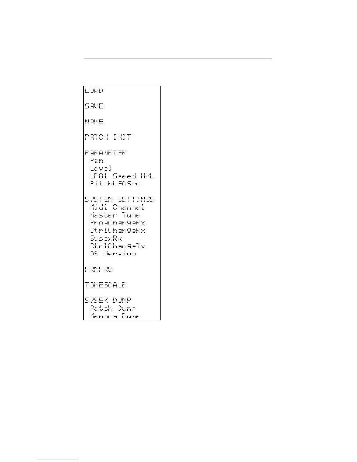
The menu of the Modor NF-1 exists out of 9 menu items. When the menu button is hit
you enter the menu, and the first menu item appears on the upper display line, while a
black dot moves from right to left over the screen. By pressing again before it reaches
the left side, the next menu item is selected. If you stop hitting ”Menu”, the black dot
reaches the left side. You now entered this submenu. Following menus can be entered:
1. LOAD: Load a patch from internal memory
2. SAVE: Save a patch in the internal memory
3. NAME: Give your patch a name
4. PATCH INIT: Initialise this patch
5. PARAMETER: To adapt a few sound parameters that have no knob on the front
panel
6. SYSTEM SETTINGS: To set some global system parameters
7. TONESCALE: Change the tuning of this patch with 1/4 notes up or down
8. FRMFRQ: Set formant frequencies of the formant filter
9. MIDI DUMP: Dump a single patch, the complete patch memory using Midi
Sysex messages
Next, after entering a certain menu, data can be selected an altered using the
SELECT-encoder and VALUE-knob. Sometimes you need to validate your choice by
pressing the MENU-button again, or you might need to approve or cancel your choice
by using SRC/YES or DEST/NO. While in the menu, on any moment you can press
DEST/NO to cancel and leave the menu.
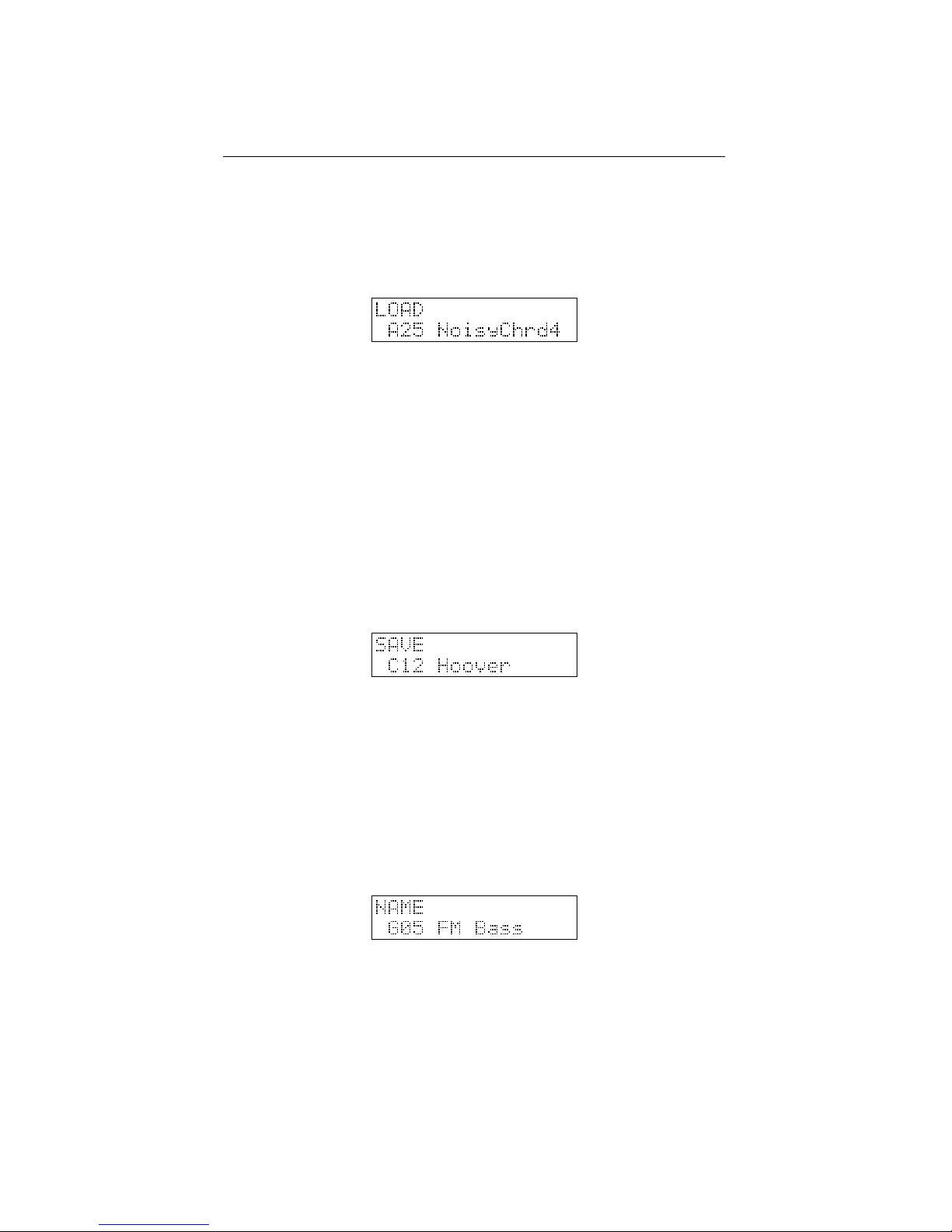
8.1 Load
After entering the Load-menu, you can select a patch in the synth’s memory using the
SELECT- and/or VALUE-control. The SELECT encoder selects a patch in the active
bank, with VALUE and/or the SRC/YES-button you choose the active patchbank. The
selected patch is temporarily loaded into the memory, and can be played on the keyboard. This way you can browse through the available patches in memory, while the
original patch you were working on does not yet get lost. Next:
37
Page 42
8.2. SAVE CHAPTER 8. MENU REFERENCE
• Pressing the No/Dest-button cancels the load-operation, exits the menu and re-
stores the active patch.
• Pressing the Menu-button gives you a choice: Load (Y/N). Use Yes/Src to finish
the load operation, or No/Dest to cancel and leave the menu. After choosing
Yes/Src the active patch is being overwritten by the selected patch from memory.
8.2 Save
After entering the Save-menu, you can use the SELECT- and VALUE-controls and
SRC/YES-button to select a spot in the synth’s memory to store your patch. The SELECT encoder selects a patch in the active bank, with VALUE and/or the SRC/YESbutton you choose the active patchbank. The patch you select is temporarily loaded in
the synth’s memory such that you can listen to the patch that’s going to be overwritten,
to make sure you don’t overwrite the wrong patch.
• Pressing the No/Dest-button cancels the save operation, and exits the menu.
• Pressing the Menu button gives you a choice: Save (Y/N). Use Yes/Src to write
the actual patch into the synth’s memory on the selected spot. No/Dest cancels
the save operation and exits the menu.
8.3 Name
In this menu, you can change the name of the actual patch with the Select and Value
buttons. Use the VALUE-control to select a character position. With the SELECTencoder you choose a character.
• Pressing the Menu or No/Dest-button you exit the menu.
• Pressing Yes/Src switches between latin characters and numbers, and cyrillic
characters.
8.4 Init Patch
If you want to start building up a new patch completely from scratch, this might be
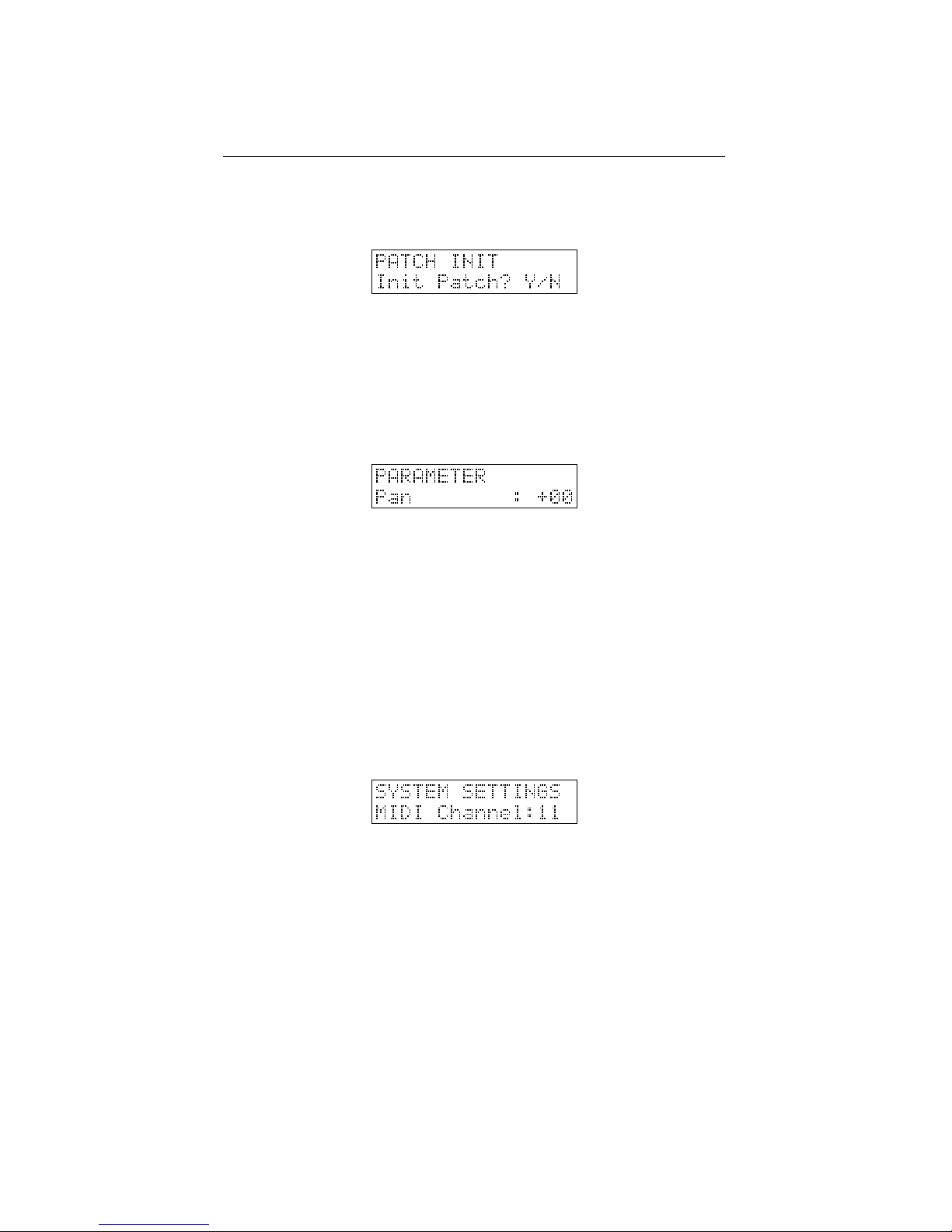
helpful. Quickly hit the MENU button four times to select the INITIALISE-menu and
38
Page 43
8.5. PARAMETER CHAPTER 8. MENU REFERENCE
wait one second to select it (the black dot reaches the left side of the screen). You
now just get two options: Initialise or Cancel, make your choice with SRC/YES or
DEST/NO.
8.5 Parameter
Although there are many controls on the Modor NF-1 frontpanel, a few parameters can
not be changed with a dedicated control. They have to be changed in the PARAMETERmenu. Select the parameter to edit using the SELECT encoder, and change it using
VALUE. Leave the menu using the MENU or NO/DEST switch.
• Pan: panoramic position of the patch in the left/right stereo image [-64,+63].
• Level: Patch volume, which is by default set at maximum [0,127].
• LFO1 Speed: choose between HI and LO speed setting for LFO1 [LO,HI]
• PitchLFOSrc: choose the source for the LFO pitch modulation [LS&H, S&H,
LFO2, LFO1]
8.6 System Settings
In this menu a few global settings can be edited. These parameters act globally and
do not depend on the selected patch. Select the parameter to edit using the SELECT
encoder, and change it using VALUE. Leave the menu using the MENU or NO/DEST
switch.
• Midi Channel: The MIDI channel upon which the midi data are received and
transmitted [1,16]
• Master Tune: Here you can change the general tuning of the synthesizer, to play
together with other instruments which might be tuned a bit higher or lower [64,+63]. At a master tune of zero, the note A5 (la in the fifth octave) has a
frequency of 440Hz.
• ProgChangeRx: choose if the Modor NF-1 responds to midi Program Change
messages or not [ON,OFF]
• CtrlChangeRx: choose if the Modor NF-1 responds to midi Control Change mes-
sages or not [ON,OFF]
• SysexRx: choose if the Modor NF-1 receives or ignores sysex messages [ON,OFF]
39
Page 44
8.7. FORMANT FREQUENCIES CHAPTER 8. MENU REFERENCE
• CtrlChangeTx: choose if the Modor NF-1 sends midi Control Change messages
when turning a control on the front panel [ON,OFF]
• OS Version: check the version number of the actually installed operating system.
8.7 Formant Frequencies
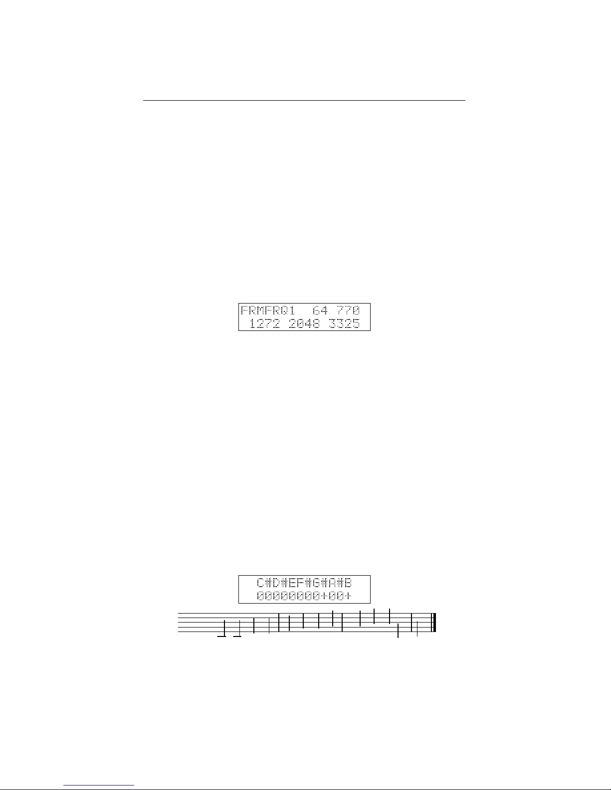
In this menu the precise setting of the formants in the formant filter can be altered in
detail. Note that you also can choose from a number of preset formant frequency sets
using the VOWEL-button in the Formant filter section. Altering the formants in this
menu can be considered as ”advanced patch editing”. Use the SELECT encoder to
select one of the three vowels 1-2-3. The VALUE knobs sets the relative volume of
this vowel. The knobs ATTACK/T1, DECAY/T3, SUSTAIN/L3 and RELEASE/T4 are
used to set the formant frequencies of the selected vowel. Thus, these knobs temporarily get another function when the FRMFRQ menu is active. Leave the menu using the
MENU or NO/DEST switch.
While changing the formant frequencies you may notice that the sound sometimes
suddenly seems to get blocked and reduced to a much weaker volume. This is a safety
compressor which gets activated whenever the formant filter becomes unstable. Not every combination of formant frequencies results into a stable filter, sometimes the filter
results just runaway and the filter would suddenly produce very loud heavily distorted
noise signals. These might damage your speakers, or worse, your ears. Therefore this
safety compressor has been installed to intervene immediately when the formant filter
gets unstable.
8.8 Tonescale
At initial settings, the Modor NF-1 has a standard tuning existing of 12 equal subdivisions (half tones) in an octave. Most modern-day western musical instruments use
this tonescale of 12 equally spaced pitches in an octave, including almost all synthesizers. This tonescale is called the ”equal-tempered tonescale”. However, many historical and ethnic instruments are capable of playing more than only this basic set of
12 halve-tones, thereby evoking strange and exotic melodies and musical characters.
For example, modern oriental music still heavily relies on the use of other tonescales
highly different from the equal-tempered scale.
Without trying to be exhaustive in the complex domain of ethnic tonescales (there
are litterally hundreds or thousands of tonescale possibilities in ethnic music), the
40
Page 45
8.9. SYSEX DUMP CHAPTER 8. MENU REFERENCE
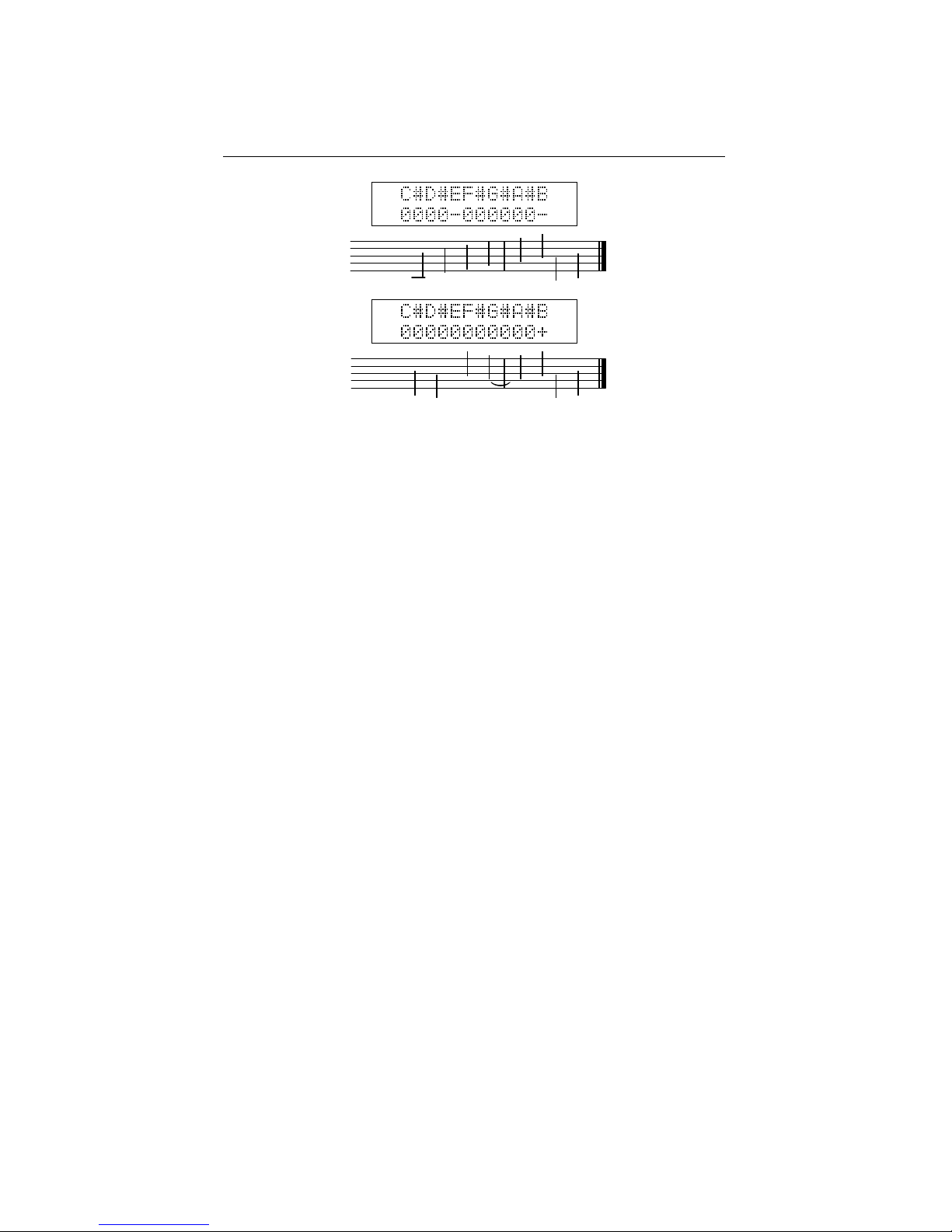
Modor NF-1 offers a possibility to vary and experiment with the tonescale. You are
able to add or subtract a quarter tone to the pitch of each one of the 12 half tones in an
octave.
In the tonescale menu, you see the 12 tones of an octave in the upper line of the
display, and a set of zeros, plus- and minus-signs on the second line. A zero means
that this tone stays at the original pitch, a set of 12 zeros means that the original equaltempered tonescale remains unchanged. A plus-signs means that the corresponding
tone in the upper line is pitched up by a quarter tone, a minus-sign means it is pitched
down by a quarter tone. Use the SELECT encoder to select one of the 12 notes, and
change it’s tuning with the VALUE control.
The tonescale is saved as part of a patch in the Modor NF-1. A patch that is used
in a song using a deviating tonescale can be saved with it’s special tonescale, without
affecting other patches. The normal tonescale is restored upon patch initialisation, or
after loading a patch with the normal tonescale. The special tonescale gets recalled
whenever the patch is loaded again.
8.9 Sysex Dump
A Sysex or ”System Exclusive” message is commonly used to send the contents of a
synth’s memory to an external device for backup or external editing, a so-called ”sysex
dump”. The contents of the memory are put into a long string of parameter numbers
and send out over midi, where an external computer or sequencer can capture and
store them. On a later moment, the sysex data can be sent back towards the synth to
restore it’s memory to the situation at the moment of the sysex dump. A way to make
”backups” of the synth’s memory, or the exchange patches between two Modor NF-1s.
Another use of sysex-messages is to perform firmware updates of a midi device’s
operating system. Instructions on how to install firmware (OS) updates are distributed
together with the OS-updates.
In the SYSEX DUMP menu you can choose between ”Patch dump” and ”Memory
dump”, turning the SELECT-control.
Patch dump With Patch Dump you send out a sysex message containing the actual
set of parameters of the active patch. Press the MENU-button once, and confirm with
SRC/YES (or cancel with DEST/NO).
41
Page 46

8.9. SYSEX DUMP CHAPTER 8. MENU REFERENCE
Memory dump A Memory Dump creates a very long sysex message containing all
of the patches in memory, from memory postions A00 upto N31. This way you can
create a backup of the complete memory of the Modor NF-1. Select the SYSEX DUMP
menu by pressing MENU 9x, turn the SELECT-control to select Memory Dump, press
MENU again, and hit SRC/YES to confirm (or cancel with DEST/NO).
Note that if the Modor NF-1 receives a Patch dump, this is not yet stored permanently in it’s memory. If you want to store the patch you received via a patch dump,
you still have to save it. This is of course different for a memory dump, where a very
large number of patches is sent through midi in a large bulk package. They are stored
permanently immediatly upon reception of the data.
Note that the Modor NF-1 cannot receive midi bulk memory dumps at any speed.
The received data need to be written into flash memory while receiving new data in the
mean time. This means that at very high data speeds, some data might get lost.
The sysex messages contain a checksum to detect bad reception, such that you will
be informed when something went wrong. Reduce the speed of your sysex program or
sequencer if you experience problems with the reception of large sysex dumps.
42
Page 47
8.10. MENU OVERVIEW CHAPTER 8. MENU REFERENCE
8.10 Menu overview
43
Page 48
9
MIDI Implementation
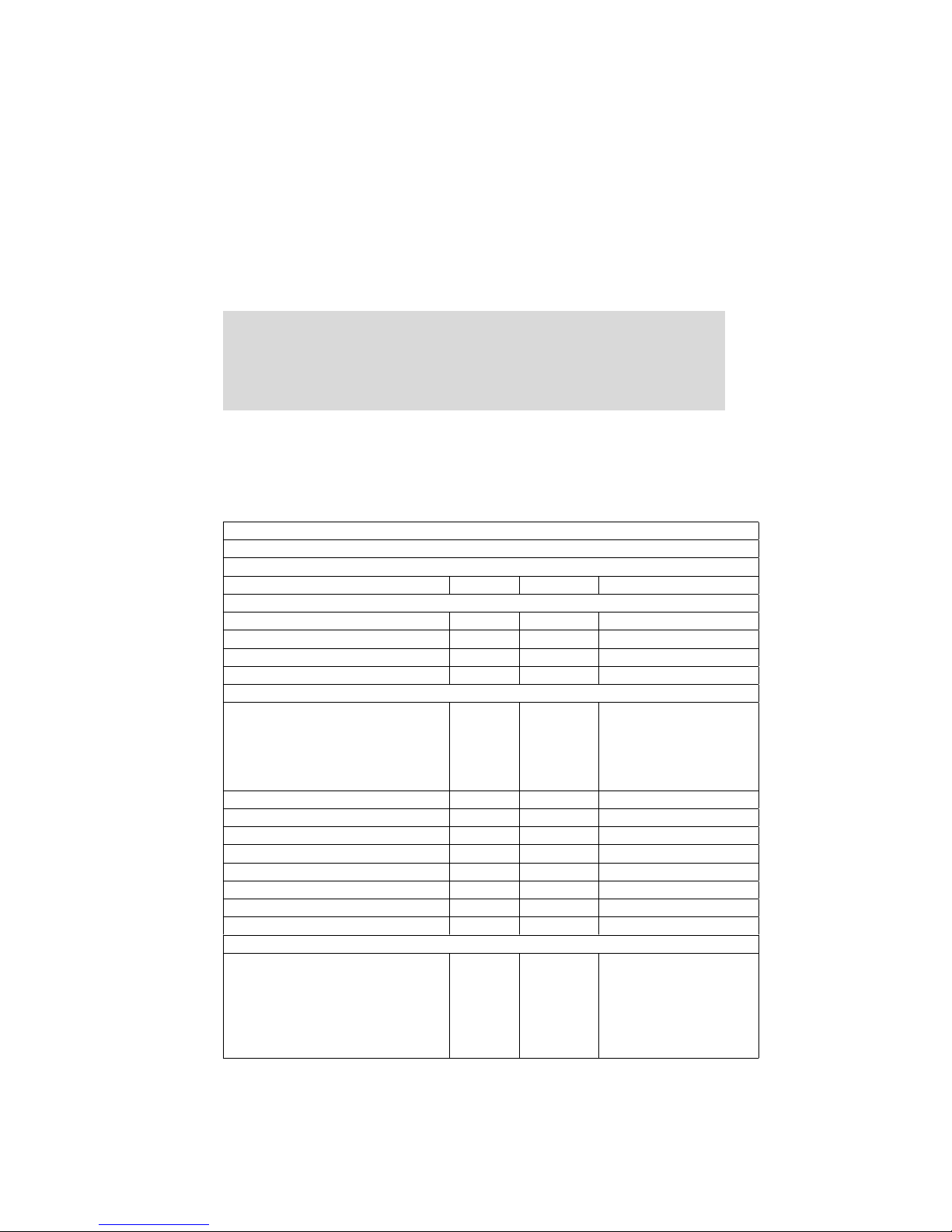
9.1 Midi implementation chart
MIDI Implementation Chart v. 2.0
Manufacturer: Modor Music Model: NF-1 Version: 1
Date: March 2015
Transmit Recognize Remarks
1. Basic Information
MIDI channels [1-16] [1-16]
Note numbers - [0-127]
Program change - [0-31]
Bank Select response? - [0-13] [A-N] via cc#0 & cc#32
Modes supported
Mode 1: Omni-On, Poly - No
Mode 2: Omni-On, Mono - No
Mode 3: Omni-Off, Poly - Yes
Mode 4: Omni-Off, Mono - No
Multi Mode - No
Note-On Velocity - Yes
Note-Off Velocity - No
Channel Aftertouch - Yes
Poly (Key) Aftertouch - Yes
Pitch Bend - Yes
Active Sensing No No
System Reset No No
Tune Request No No
Universal System Exclusive:
Sample Dump Standard No No
Device Inquiry No No
File Dump No No
MIDI Tuning No No
Master Volume No No
Master Balance No No
44
Page 49
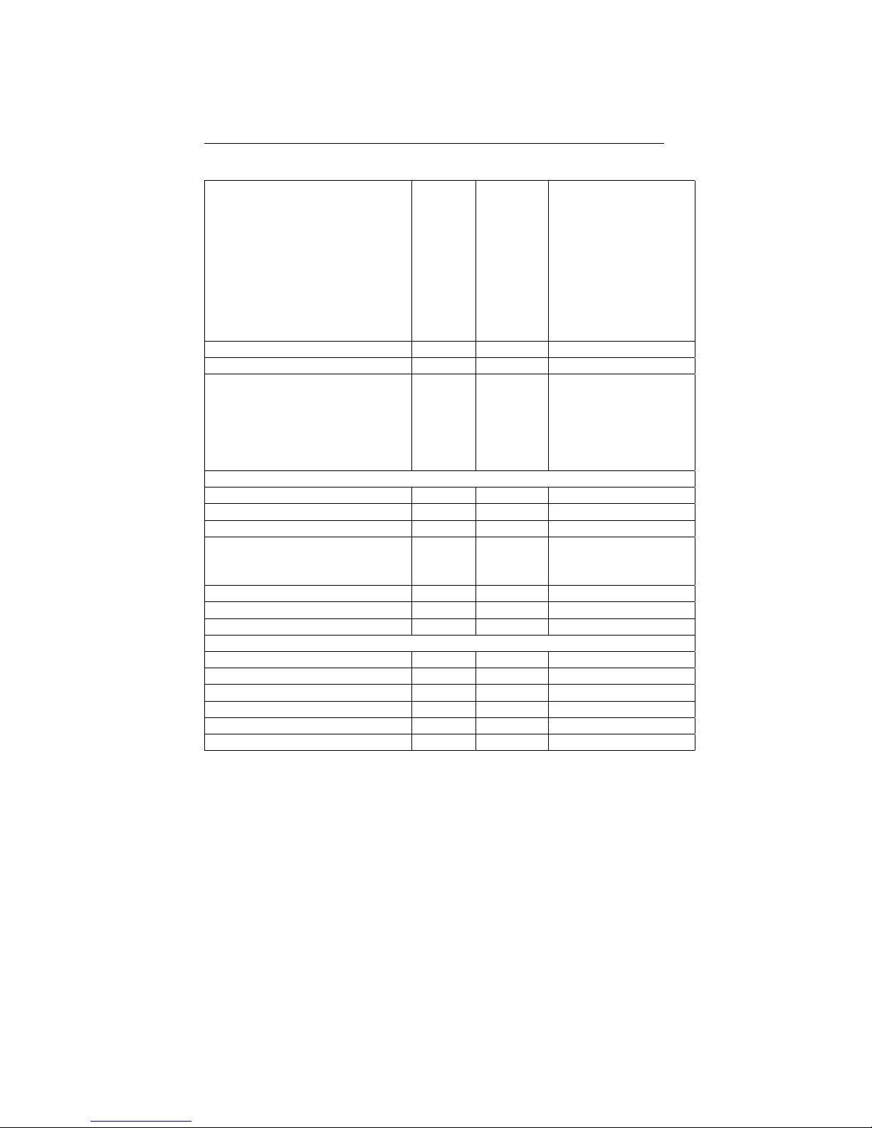
9.1. MIDI IMPLEMENTATION CHART CHAPTER 9. MIDI IMPLEMENTATION
Notation Information No No
Turn GM1 System On No No
Turn GM2 System On No No
Turn GM System Off No No
DLS-1 No No
File Reference No No
Controller Destination No No
Key-based Instrument Ctrl No No
Master Fine/Coarse Tune No No
Other Universal System Exclusive No No
Manufacturer System Exclusive No No
NRPNs No No
RPN 00 (Pitch Bend Sensitivity) No No
RPN 01 (Channel Fine Tune) No No
RPN 02 (Channel Coarse Tune) No No
RPN 03 (Tuning Program Select) No No
RPN 04 (Tuning Bank Select) No No
RPN 05 (Modulation Depth Range) No No
2. MIDI Timing and Synchronization
MIDI Clock No Yes
Song Position Pointer No No
Song Select No No
Start No Yes
Continue No Yes
Stop No Yes
MIDI Time Code No No
MIDI Machine Control No No
MIDI Show Control No No
3. Extensions Compatibility
General MIDI compatible? No No
Is GM default power-up mode? No No
DLS compatible? No No
Standard MIDI Files No No
XMF Files No No
SP-MIDI compatible? No No
45
Page 50

9.2. MIDI CONTROLLER LIST CHAPTER 9. MIDI IMPLEMENTATION
9.2 Midi controller list
Control Function Transmitted Received Remarks
0 Bank select No Yes Bank A - N
1
1 Modulation wheel No Yes Mod Source MODW
2 No No
3 No No
4 No No
5 Portamento Yes Yes
6 No No
7 Volume pedal No Yes Mod source PEDL
8 No No
9 No No
10 Pan Yes Yes
11 No No
12 No No
13 Osc 1 mod LFO1 Yes Yes
14 Osc 2 mod LFO1 Yes Yes
15 Osc 3 mod LFO1 Yes Yes
16 Osc 1 mod ENV2 Yes Yes
17 Osc 2 mod ENV3 Yes Yes
18 Osc 3 mod ENV4 Yes Yes
19 Yes Yes
20 No No
21 No No
22 Comb filter delay Yes Yes
23 LFO 2 speed Yes Yes
24 Comb filter feedback Yes Yes
25 No No
26 Comb filter speed Yes Yes
27 Comb filter mix Yes Yes
28 Delay time Yes Yes
29 Delay filter Yes Yes
30 Delay mix Yes Yes
31 No No
32 Bank select Yes Yes Bank A - N
1
33 Pitch ENV1 Yes Yes
34 Pitch LFO-S&H Yes Yes Source can be selected
35 Comb filter depth Yes Yes
36 Filter ENV2 Yes Yes
37 Filter LFO2 Yes Yes
38 Filter KEYB Yes Yes
39 Formant ENV3 Yes Yes
40 Formant LFO2 Yes Yes
41 Vowel 1 volume Yes Yes
42 Vowel 2 volume Yes Yes
43 Vowel 3 volume Yes Yes
46
Page 51

9.2. MIDI CONTROLLER LIST CHAPTER 9. MIDI IMPLEMENTATION
Control Function Transmitted Received Remarks
44 Wire 1 amount Yes Yes
45 Wire 2 amount Yes Yes
46 Wire 3 amount Yes Yes
47 Wire 4 amount Yes Yes
48 Wire 5 amount Yes Yes
49 Wire 6 amount Yes Yes
50 Wire 7 amount Yes Yes
51 Delay feedback Yes Yes
52 LFO3 speed Yes Yes
53 S&H speed Yes Yes
54 Yes Yes
55 Osc 1 coarse tuning Yes Yes
56 Osc 2 coarse tuning Yes Yes
57 Osc 3 coarse tuning Yes Yes
58 Osc 1 fine tuning Yes Yes
59 Osc 2 fine tuning Yes Yes
60 Osc 3 fine tuning Yes Yes
61 Osc 1 volume Yes Yes
62 Osc 2 volume Yes Yes
63 Osc 3 volume Yes Yes
64 Sustain pedal No Yes On or Off
2
65 Osc 1 mod Yes Yes
66 Osc 2 mod Yes Yes
67 Osc 3 mod Yes Yes
68 Volume No Yes
69 No Yes
70 Noise level Yes Yes
71 Filter frequency Yes Yes
72 Formant morph Yes Yes
73 Formant mix Yes Yes
74 Filter resonance Yes Yes
75 LFO 1 speed Yes Yes
76 Drive Yes Yes
77 Ring volume Yes Yes
78 ENV 1 T1 Yes Yes
79 ENV 2 T1 Yes Yes
80 ENV 3 T1 Yes Yes
81 ENV 4 T1 Yes Yes
82 ENV 1 T2 Yes Yes
83 ENV 2 T2 Yes Yes
84 ENV 3 T2 Yes Yes
85 ENV 4 T2 Yes Yes
86 ENV 1 T3 Yes Yes
87 ENV 2 T3 Yes Yes
88 ENV 3 T3 Yes Yes
89 ENV 4 T3 Yes Yes
90 ENV 1 T4 Yes Yes
47
Page 52

9.2. MIDI CONTROLLER LIST CHAPTER 9. MIDI IMPLEMENTATION
Control Function Transmitted Received Remarks
91 ENV 2 T4 Yes Yes
92 ENV 3 T4 Yes Yes
93 ENV 4 T4 Yes Yes
94 ENV 1 L1 Yes Yes
95 ENV 2 L1 Yes Yes
96 ENV 3 L1 Yes Yes
97 ENV 4 L1 Yes Yes
98 ENV 1 L2 Yes Yes
99 ENV 2 L2 Yes Yes
100 ENV 3 L2 Yes Yes
101 ENV 4 L2 Yes Yes
102 ENV 1 L3 Yes Yes
103 ENV 2 L3 Yes Yes
104 ENV 3 L3 Yes Yes
105 ENV 4 L3 Yes Yes
106 Vowel 1 formant 1 Yes Yes
107 Vowel 1 formant 2 Yes Yes
108 Vowel 1 formant 3 Yes Yes
109 Vowel 1 formant 4 Yes Yes
110 Vowel 2 formant 1 Yes Yes
111 Vowel 2 formant 2 Yes Yes
112 Vowel 2 formant 3 Yes Yes
113 Vowel 2 formant 4 Yes Yes
114 Vowel 3 formant 1 Yes Yes
115 Vowel 3 formant 2 Yes Yes
116 Vowel 3 formant 3 Yes Yes
117 Vowel 3 formant 4 Yes Yes
118 No No
119 No No
120 No No
121 No No
122 No No
123 All notes off No Yes
124 No No
125 No No
126 No No
127 No No
1
MSB(CC#0) and LSB(CC#32) have identical functions.
2
Sustain pedal [0-63]=Off, [64-127]=On
48
 Loading...