

Modine Manufacturing VE, HER, PTE Wiring Diagram

2-424.6
March, 2016
WIRING DIAGRAMS
Models HER, VE, PTE electric unit heaters
Two-In One Diagrams
Two wiring diagrams are furnished for each circuit configuration
in this manual. Included are a connection diagram at the left
for field installation and a circuit schematic at the right to aid in
continuity and trouble shooting.
Solid lines show pre-wiring performed at the factory; dotted
lines inform the installer of connections required to put the
heater in operation.
NOTE: As indicated in every diagram, all wiring must comply
with the National Electrical Code and all local codes. All
components must agree with their respective power source.
Wiring Diagram Selection
Diagrams are readily identified in the page location index on
the following page. This allows for the correct wiring diagram
to be selected using the model, size, and power code of the
unit heater.
Select the correct wiring diagrams as follows:
1. Determine unit heater model and size.
2. Select power code number from Table 2.3.
3. Reference unit heater model in the Page Location Index
(Table 2.4) with power code number of the corresponding
wiring diagram.
CAUTION
Turn off all power to unit before wiring. Failure to wire this unit
according to this wiring diagram may result in injury to the
installer or user. For deviations, contact factory.
Abbreviations and Symbols
To facilitate interpretation and enable simplification
the abbreviations and symbols have been selected as
recommended by ANSI (American National Standards
Institute) and NEMA (National Electrical Manufacturers
Association) standards.
XFMR or TR Transformer
V Volts
Hz Cycle or Hertz
φ Phase
LC Limit Control
THERM or TH Thermostat
G Ground
HTR Heater
H Hot or High
SW Switch
C Common
"J" Box Junction Box
L Low
H1, H2, etc. Transformer Primary Terminals
O.L.C. Overload Contact
R Relay
Rc Relay Contact
VA Volt-Ampere
X1,X2, etc. Transformer Secondary Terminals
L1, L2, etc. Electric Load Terminals
T1, T2, etc. Starter or Motor Terminals
Wire Color Coding
BK Black
BU Blue
R Red
W White
Y Yellow
Wire Color Coding
BK Black
BL Blue
R Red
W White
Y Yellow
X1,X2, etc. Transformer Secondary Terminals
L1, L2, etc. Electric Load Terminals
T1, T2, etc. Starter or Motor Terminals
2-424.5 — WIRING DIAGRAMS MODELS HER, VE, PTE
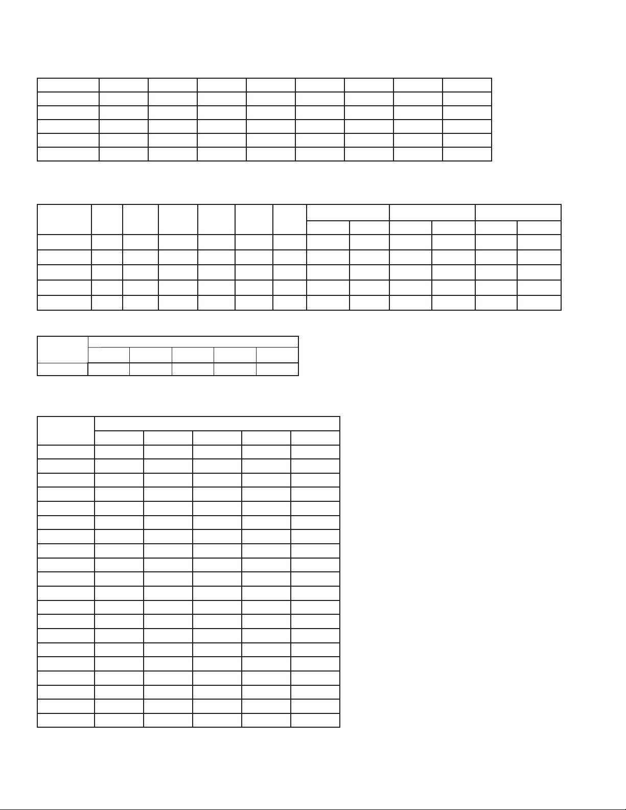
Table 2.1
Unit Power Requirements (AMPS) - HER Models
Power Supply HER 30 HER 50 HER 75 HER100 HER125 HER150 HER200 HER250
208/1 14.9 24.5 36.5 49.4 - - - -
240/1 12.9 21.3 31.7 42.9 - - - -
208/3 8.8 14.3 21.3 29.0 36.0 42.9 56.8 70.7
240/3 7.7 12.5 18.5 25.3 31.4 37.4 49.4 61.4
480/3 3.8 6.5 9.5 13.3 16.3 19.3 25.3 31.4
Table 2.2
Unit Power Requirements (AMPS) - VE & PTE Models
Power Supply VE50 VE75 VE100 VE150 VE200 VE200
208/1 - - - - - - - - - - - -
240/1 21.4 31.9 42.3 - - - - - - - - -
208/3 14.5 21.4 28.3 42.5 - - - - - - - -
240/3 12.7 18.6 24.6 37.0 49.0 - - - - - -
480/3 6.7 9.7 12.7 19.0 25.0 31.0 19.5 37.6 25.5 49.6 31.5 61.5
Table 2.3
Power Code Selection
Power Supply (Volts/Phase)
208V/1 240V/1 208V/3 240V/3 480V/3
Power Code 11 12 31 32 33
VE/PTE300 VE/PTE400 VE/PTE500
1-stage 2-stage 1-stage 2-stage 1-stage 2-stage
Table 2.4
Electric Unit Heater Page Location Index
Model No.
HER 30 3 3 5 5 8
HER 50 3 3 5 5 8
HER 75 3 3 5 5 8
HER100 4 4 5 5 8
HER125 - - 5 5 8
HER150 - - 6 5 8
HER200 - - 7 7 8
HER250 - - 7 7 8
VE 50 - 9 10 10 11
VE 75 - 9 10 10 11
VE100 - 9 10 10 11
VE150 - - 13 13 14
VE200 - - - 13 14
VE250 - - - - 14
VE300 - - - - 12
VE400 - - - - 12
VE500 - - - - 12
PTE300 - - - - 12
PTE400 - - - - 12
PTE500 - - - - 12
11 12 31 32 32
Power Code
2
2-424.5 — WIRING DIAGRAMS MODELS HER, VE, PTE
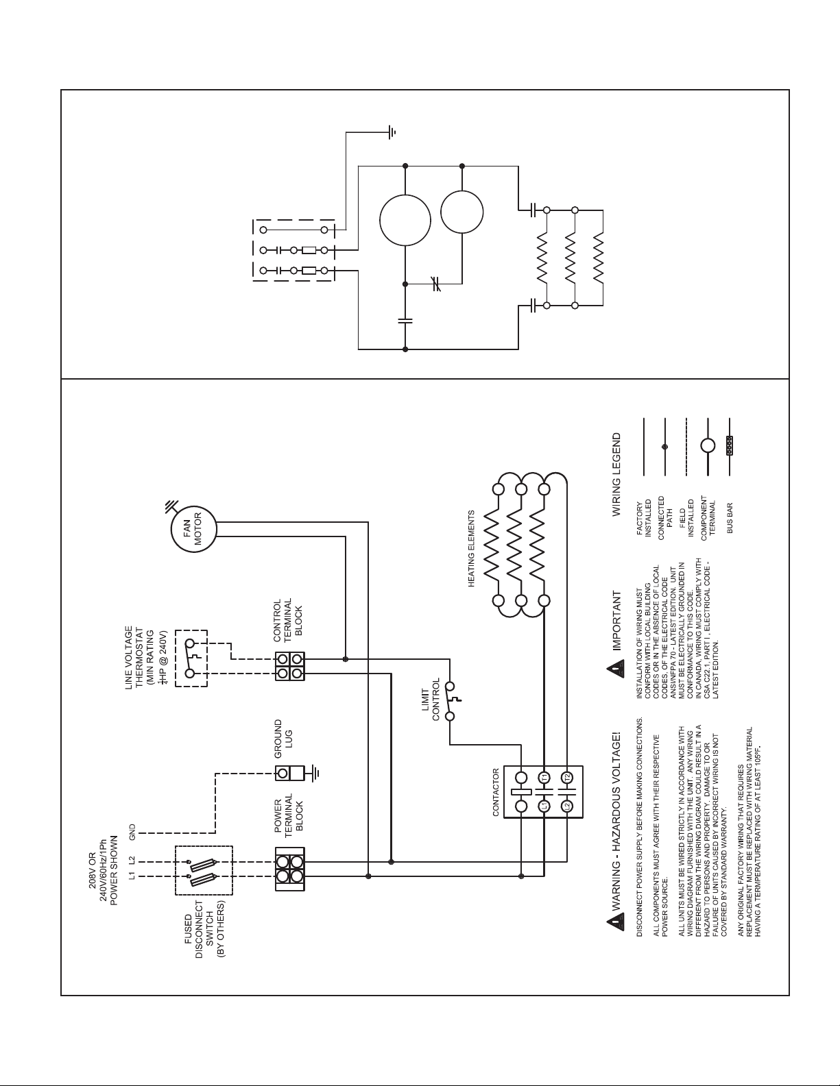
POWER SUPPLY
208V OR 240V/60 Hz/1
Ø
LUG
GROUND
FUSED DISCONNECT
SWITCH (BY OTHERS)
CONTACTOR
HEATING ELEMENTS
LIMIT
CONTROL
THERM
MOTOR
FAN
COIL
5H70253A1 208V or 240V, single-phase power supply, 3kw, 5kw, 7.5kw Horizontal Models
3
2-424.5 — WIRING DIAGRAMS MODELS HER, VE, PTE
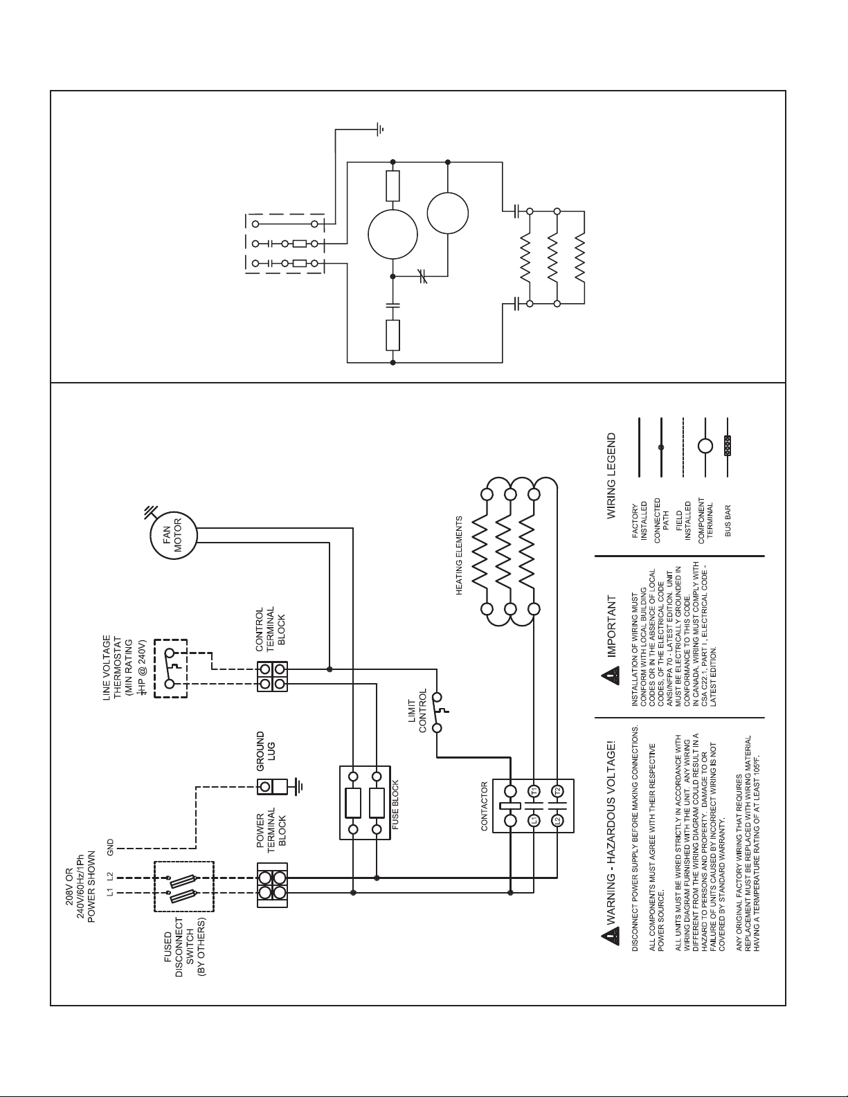
FUSE FUSE
POWER SUPPLY
208V OR 240V/60 Hz/1
Ø
LUG
GROUND
FUSED DISCONNECT
SWITCH (BY OTHERS)
CONTACTOR
HEATING ELEMENTS
LIMIT
CONTROL
THERM
MOTOR
FAN
COIL
5H70253A2 REV F 208V or 240V, single-phase power supply, 10kw Horizontal Model
4
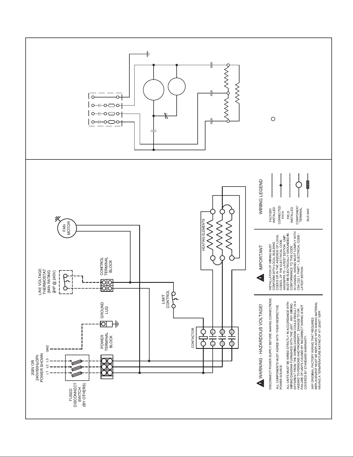
2-424.5 — WIRING DIAGRAMS MODELS HER, VE, PTE
LUG
GROUND
FUSED DISCONNECT
Ø
POWER SUPPLY
208V OR 240V/60Hz/3
SWITCH (BY OTHERS)
FAN
MOTOR
THERM
COIL
CONTACTOR
LIMIT
CONTROL
HEATING ELEMENTS
only
Ø
15kw on 240V/3
1
5H70253A4 REV E 208V or 240V, three-phase power supply, 3kw, 5kw, 7.5kw, 10kw, 12.5kw, 15kw Horizontal Models
5
 Loading...