

Modine Manufacturing PV 75, PV 100, PV 125, PV 145, PV 175 Wiring Diagrams
...
Diagram Selection
Diagrams are provided for both single- and three-phase circuits,
and are readily identified in the Selection Table on the following
page. The Selection Table enables easy selection of the correct
wiring diagram after the electrical components of the unit heater
have been determined. The control codes are listed to aid in
locating the correct diagram.
Diagram Interchangeability
The following gas-fired unit heater wiring diagrams are for either
115-volt, 60-Hertz, single-phase power, or for 230-volt, 575-volt,
60 Hertz, three-phase electrical service.
The 115v/60Hz/1φ diagrams may also be utilized for
230v/60Hz/1φ by substituting 230-volt components in the 115volt shown.
The 230v/60Hz/3φ diagrams may be modified to 460v/60Hz/3φ
by adding a 460v to 230v step down transformer and wiring the
unit as shown in the wiring “inset” on all 3-phase wiring
diagrams.
The 460v/60Hz/3φ diagrams may be modified to 575v/60Hz/3φ
by adding a 575v to 230v transformer and wiring the unit as
shown in the wiring “inset” on all 3 phase diagrams.
NOTE:
As indicated in every diagram, all wiring must comply
with the national electrical code and all local codes. All
components must agree with their respective power source.
To facilitate interpretation and enable simplification the
abbreviations and symbols have been selected as
recommended by ANSI (American National Standards
Institute) and NEMA (National Electrical Manufacturers
Association) standards.
XFMR or TR Transformer
V Volts
Hz Cycle or Hertz
φ Phase
LC Limit Control
THERM or TH Thermostat
MV Main Valve
PV Pilot Valve
SO Shut Off
RC Relay Contact or Coil
G Ground
H Hot
SW Switch
EPS Electric Pilot Switch
HI High
Lo Low
C Common
“J” Box Junction Box
H1, H2, etc. Transformer Primary Terminals
SUM Summer Contact (Summer/Winter
Switch)
WIN Winter Contact (Summer/Winter
Switch)
S-W Summer/Winter Switch
O.L.C. Overload Contact
C.S. Power Venter Centrifugal Switch
FTc Fan Timer Contact
SPDT Single-Pole Double-Throw Switch
VA Volt-Ampere
W Watts
WIRE COLOR CODING
BK Black
BL Blue
R Red
W White
Y Yellow
X1, X2, etc. Transformer Secondary Terminals
L1, L2, etc. Electric Load Terminals
T1, T2, etc. Starter or Motor Terminals
November, 1997
WIRING DIAGRAMS
Models PV/BV gas-fired unit heaters
(manufactured after April, 1994)
6-440.2
Abbreviations and Symbols
CAUTION
Turn off all power and gas to unit before wiring. Failure to
wire this unit according to the specified wiring diagram may
result in injury to the installer or user. For deviations, contact
factory.
!!
MOTOR DATA
i
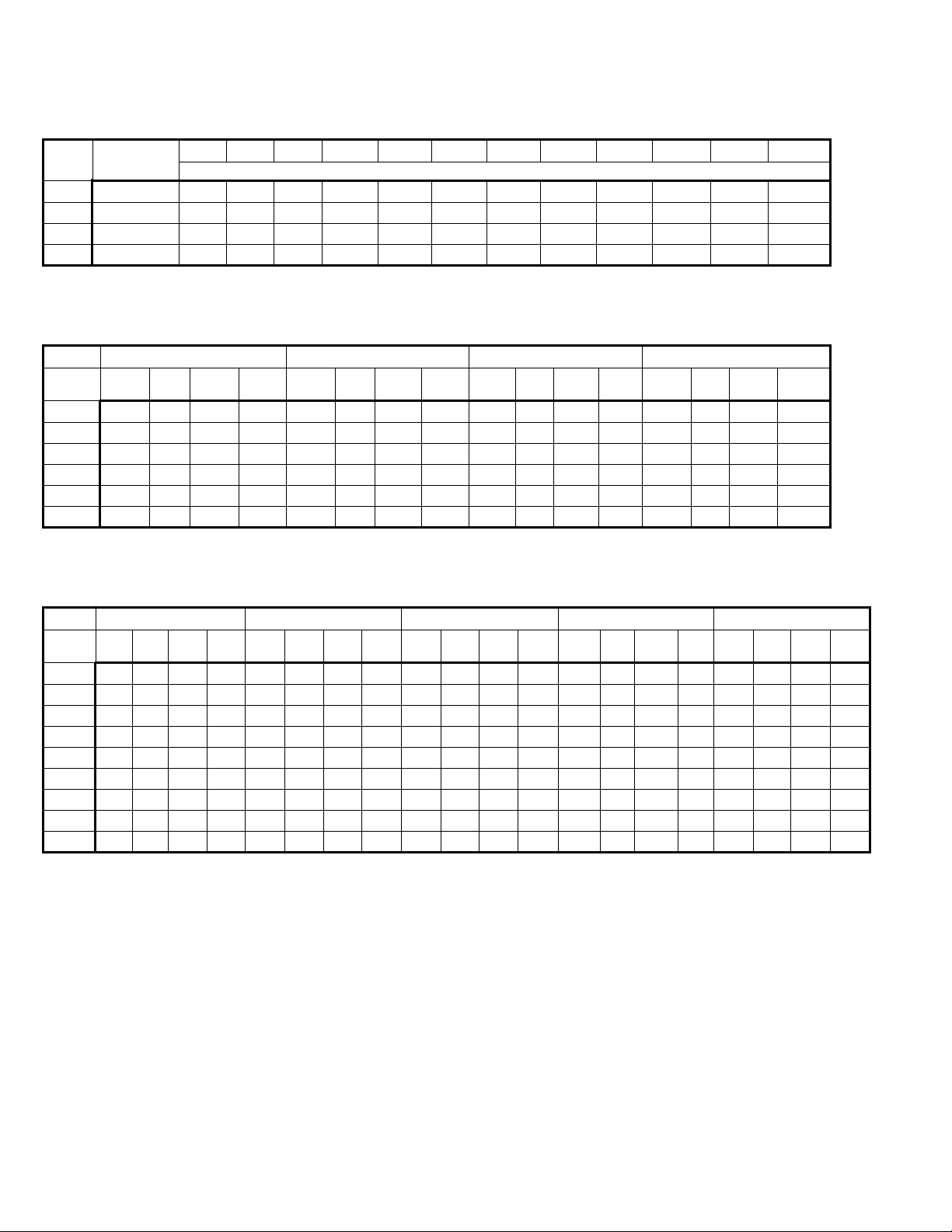
Table 1
Power Code Description — Propeller PV Models
Table 2
Motor Data and Unit Power Requirement — Propeller PV Models
Table 3
Motor Data and Unit Power Requirements — Blower BV Models
Power Electric
PV 30 PV 50 PV 75 PV 100 PV 125 PV 145 PV 175 PV 200 PV 250 PV 300 PV 350 PV 400
Code Power
Horsepower
01
115/60/1 1/40 1/40 1/30 1/30 1/15 1/6 1/6 1/6 1/3 1/3 3/4 3/4
02
230/60/1 1/40 1/40 1/15 1/15 1/15 1/6 1/6 1/6 1/3 1/3 3/4 3/4
04
200/60/3 – – – – 1/3 1/3 1/3 1/3 1/3 1/3 3/4 3/4
05
230/460/60/3 – – – – 1/3 1/3 1/3 1/3 1/3 1/3 3/4 3/4
Voltage 115/60/1 230/60/1 200/60/3 230/460/60/3
Mtr. Mtr. Total Total Mtr. Mtr. Total Total Mtr. Mtr. Total Total Mtr. Mtr. Total Total
HP Amps Rpm Amps Watts Amps Rpm Amps Watts Amps Rpm Amps Watts Amps Rpm Amps Watts
1/40
1.0 1550 2.7 175 0.5 1550 1.3 175 – – – – – – – –
1/30
2.1 1050 3.7 240 – – – – – – – – – – – –
1/15
2.4 1050 4.1 285 1.3 1050 2.2 285 – – – – – – – –
1/6
2.8 1075 5.1 440 1.6 1075 2.8 360 – – – – – – – –
1/3
5.4 1075 7.7 665 2.5 1075 3.9 585 1.9 1140 3.3 615 2.1/1.1 1140 3.4/1.7 615
3/4
8.8 1075 11.1 1050 4.4 1075 5.7 1000 3.7 1140 4.9 1020 3.4/1.7 1140 5.0/2.5 1020
Voltage 115/60/1 230/60/1 200/60/3 230/460/60/3 575/60/3
Mtr. Mtr. Total Total Mtr. Mtr. Total Total Mtr. Mtr. Total Total Mtr. Mtr. Total Total Mtr. Mtr. Total Total
HP Amps Rpm Amps Watts Amps Rpm Amps Watts Amps Rpm Amps Watts Amps Rpm Amps Watts Amps Rpm Amps Watts
1/4
5.4 1725 7.7 570 2.7 1725 4.0 520 1.6 1725 2.8 500 1.4/0.7 1725 2.7/1.4 500 0.6 1725 1 500
1/3
5.0 1725 6.9 565 2.5 1725 3.6 515 1.8 1725 3.0 530 1.6/0.8 1725 2.9/1.5 530 0.7 1725 1.2 530
1/2
8.5 1725 10.8 780 3.8 1725 5.1 730 2.5 1725 3.7 730 2.6/1.3 1725 3.9/2.0 730 1 1725 1.4 730
3/4
11.0 1725 13.3 1050 5.5 1725 6.8 1000 3.2 1725 4.4 970 3.0/1.5 1725 4.3/2.2 970 1.2 1725 1.6 970
1
13.4 1725 15.7 1260 6.7 1725 8.0 1210 4.0 1725 5.2 1230 3.8/1.9 1725 5.1/2.6 1230 1.6 1725 2 1230
1-1/2
15.0 1725 17.6 1740 7.5 1725 8.9 1690 5.6 1725 6.8 1630 5.2/2.6 1725 6.5/3.3 1630 2 1725 2.4 1630
2
– – – – – – – – 6.8 1725 8.1 2080 6.6/3.3 1725 7.9/4.0 2080 2.4 1725 2.8 2080
3
– – – – – – – – 10.6 1725 11.8 3430 8.8/4.4 1725 10.1/5.1 3430 4.1 1725 4.5 3430
5
– – – – – – – – 14.3 1725 15.5 4530 13.2/6.6 1725 14.5/7.3 4530 5.3 1725 5.7 4530
WIRING DIAGRAM SELECTION
ii
Wiring Diagram Selection
A. Field and Submittal Wiring Diagram Selection
Wiring in the field changes little when the brand of the
controls furnished on the unit heater changes. Select correct
wiring diagrams as follows:
1. Determine unit heater model and size.
2. Select control code number from Table 4.
3. Reference unit heater model in the Page Location
Index with control code number and determine correct
page number for single-phase or three-phase control.
Single-phase wiring diagram page numbers are in the
upper left of box and three-phase diagrams are in the
lower right of box.
4. Wiring diagrams for unit heat accessories are listed in
Table 5. Use the accessory diagrams along with the
unit wiring diagrams for complete wiring instructions.
B. Service and Troubleshooting
Because internal or factory wiring may vary depending on
controls manufacturer, the wiring diagrams must be selected
with the series identity number when servicing or
troubleshooting unit heater control system. Wiring diagrams in
this bulletin are for unit heaters manufactured after April 1995.
The series identity number is the 5th through the 7th digits of
the unit heater serial number.
EXAMPLE:
Serial no. — 1510101
0495-0098 has a
series identity number of 101.
To select the correct wiring diagram:
1. Determine unit heater model and size from serial plate
located on the side of the unit.
2. Determine the control code numbers from box marked
Control Code
, also on the serial plate.
3. Determine the
series identity number
of the unit heater,
then proceed with Step 3 of Field and Submittal Wiring
Diagram Selection.
Example Selection
Select correct single-phase wiring diagram for a PV 175A
Control Code 11, series identity number 101.
Locate the page which shows the wiring diagram number for PV
and BV units with series identity number 101 (see page iii).
Select the page number where the column for the PV 175
intersects with the line for control code 11. The correct wiring
diagram can be found on page 9 as shown in the upper left
hand corner of box. If this unit also had a summer/winter switch,
the accessory wiring diagram found on page C-1 as per Table 5
would also be required for complete wiring information.
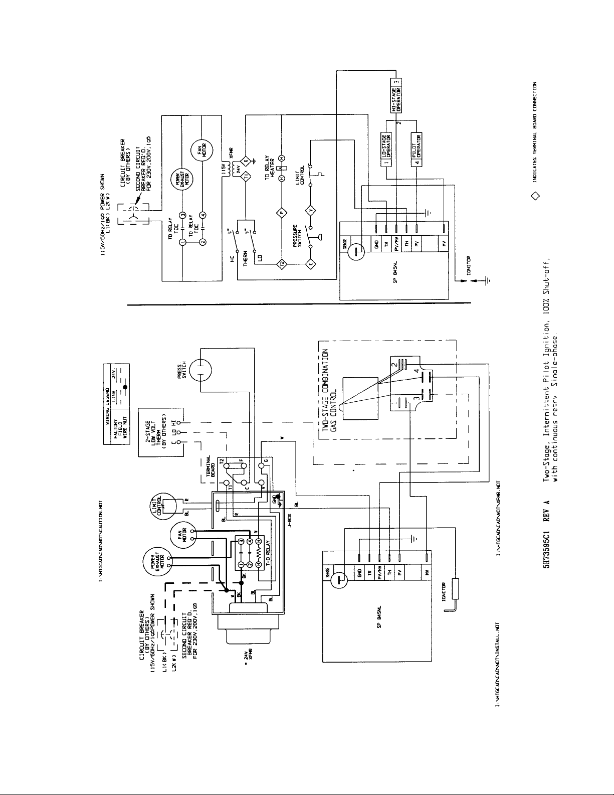
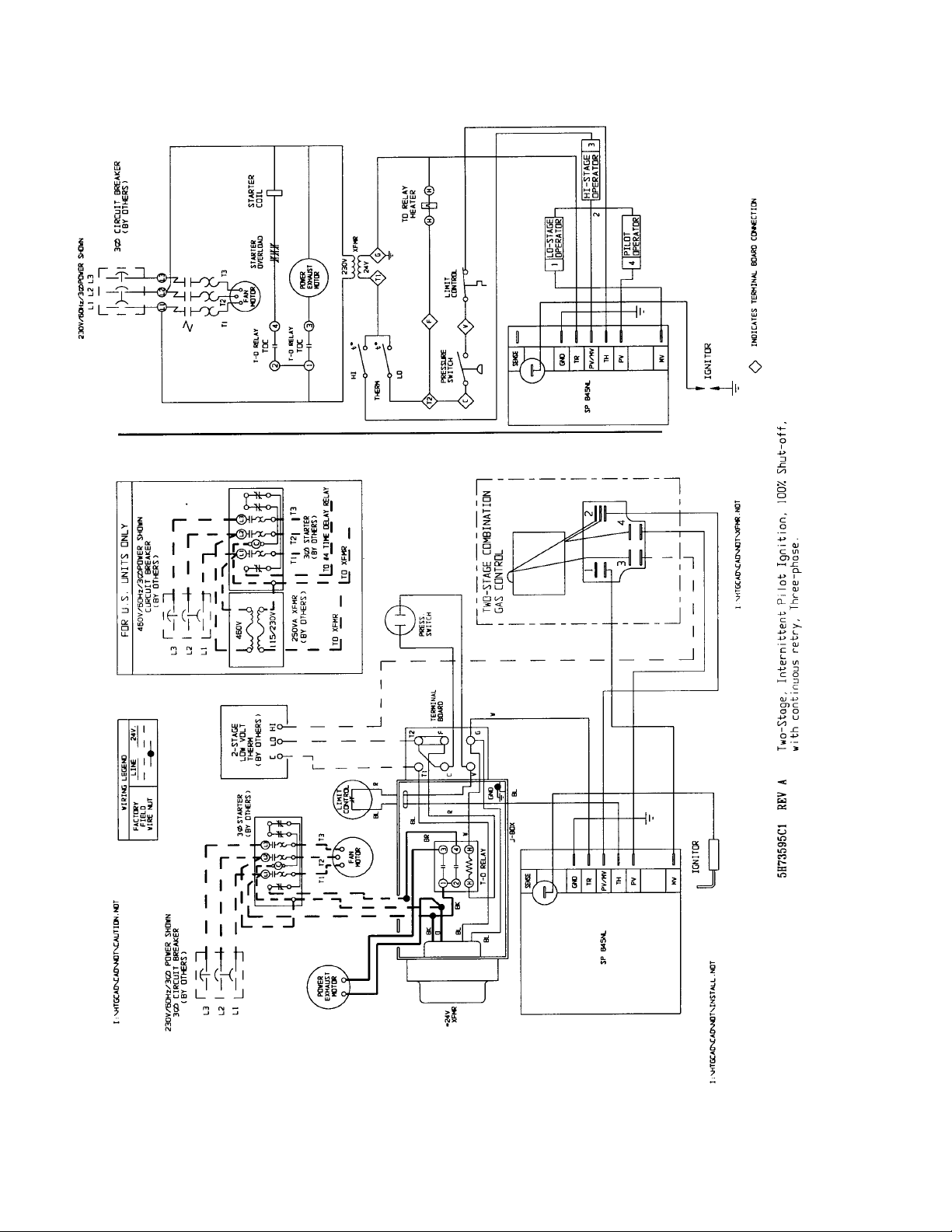
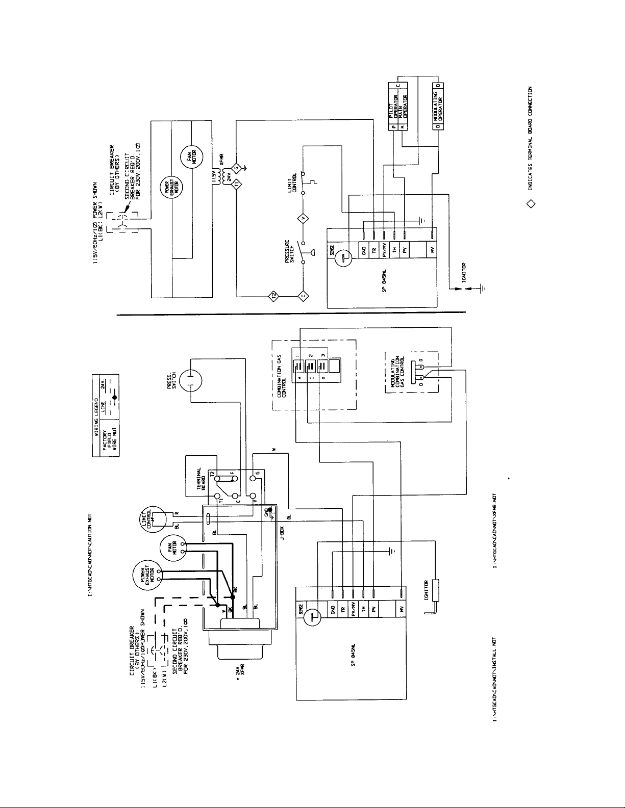
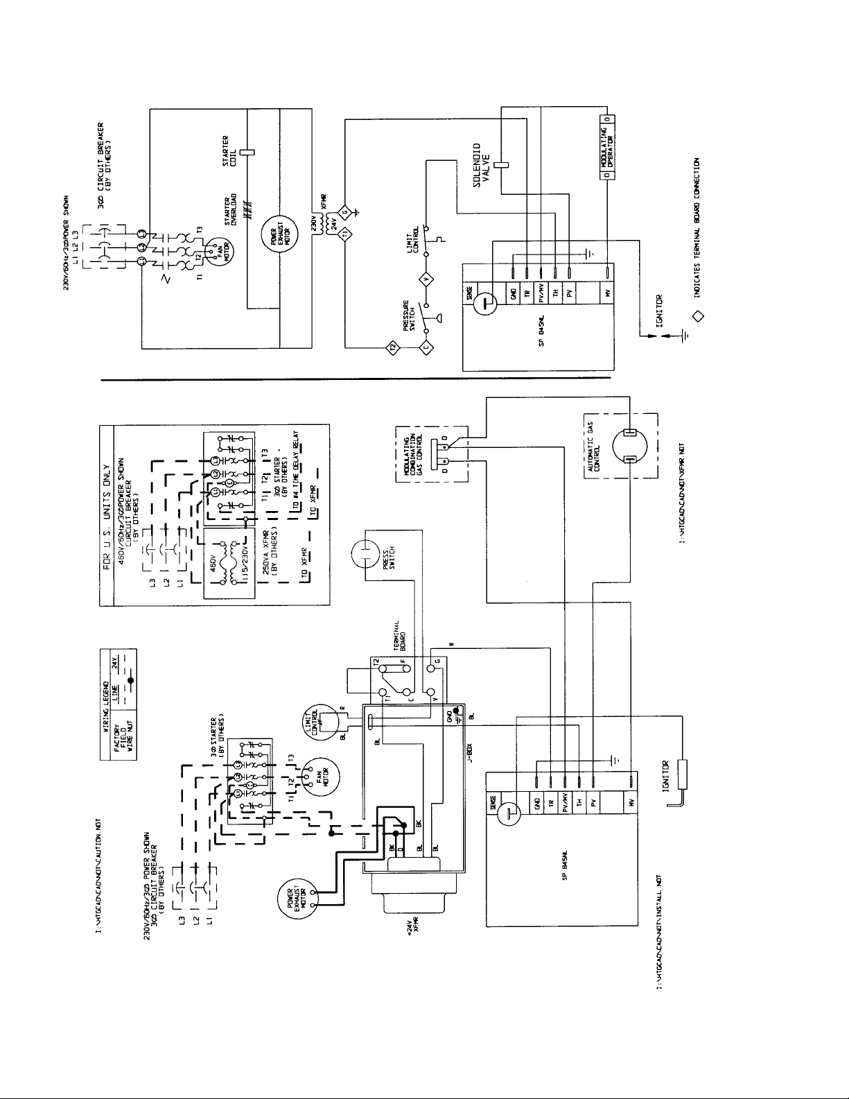
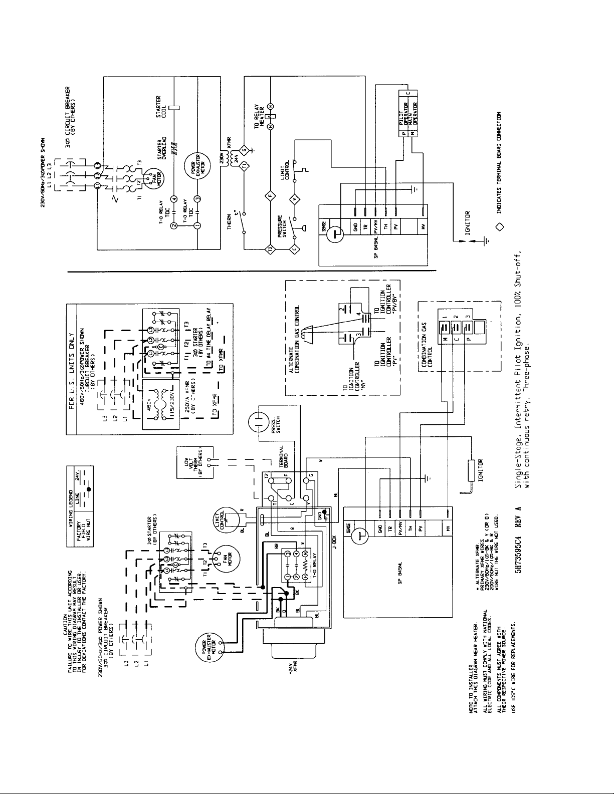
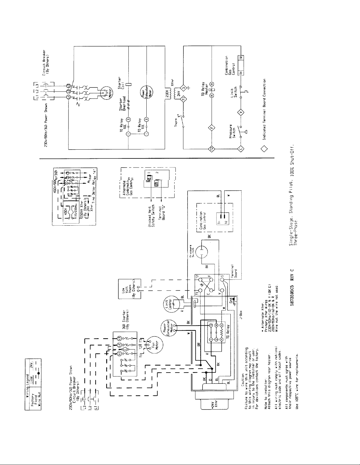
Two-in-One Diagrams
Two wiring diagrams are furnished for each circuit configuration
in this manual. Included are a connection diagram at the left for
field installation and circuit schematic at the right to aid in
continuity and troubleshooting.
The heavier lines in the connection diagram indicate line
voltage; the lighter lines indicate low voltage. Solid lines show
pre-wiring performed at the factory; dotted lines inform the
installer of connections required to put the heater in operation.
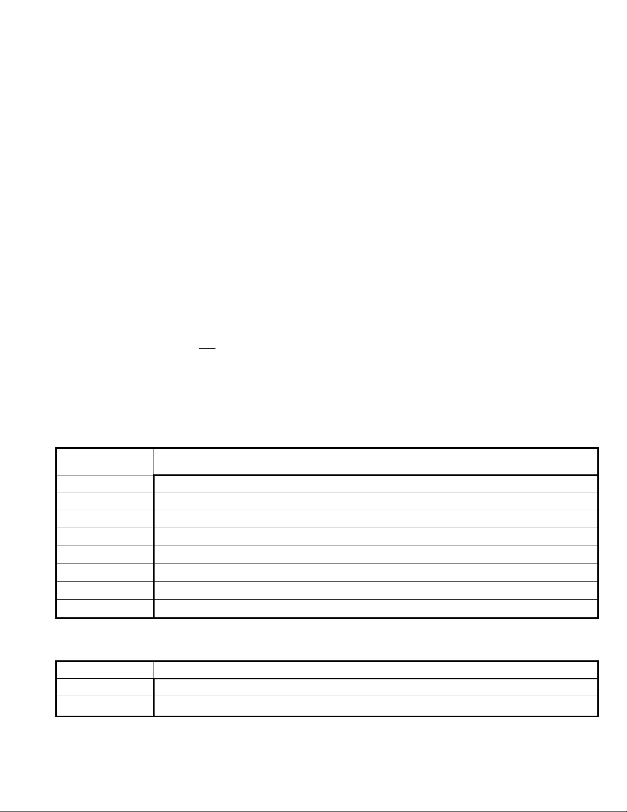
Table 4
Control Code Descriptions
Control Code
Number Description
11, 12, 13,14
Single-stage, Standing pilot, 100% shut-off, Natural gas.
30, 31, 32, 33
Single-stage, Intermittent pilot ignition, 100% shut-off with continuous retry, Natural gas.
59, 60
Mechanical modulation with automatic pilot ignition, 100% shut-off with continuous retry, Natural gas, BV only.
63, 64
Two-stage, Intermittent pilot ignition, 100% shut-off continuous retry, Natural gas.
81, 82, 91, 92
Single-stage, Standing pilot, 100% shut-off, Propane gas.
85, 86, 93, 94
Single-stage, Intermittent pilot ignition, 100% shut-off with continuous retry, Propane gas.
87, 88
Two-stage, Intermittent pilot ignition, 100% shut-off with continuous retry, Propane gas.
89, 90
Mechanical modulation with automatic pilot ignition, 100% shut-off with continuous retry, Propane gas, BV only.
Table 5
Accessory Wiring Diagram Page Location Index ➀
Page Accessory
C-1
Summer/winter switch
C-2
Energy-saver kit
➀ See paragraph A, step 4 under “wiring diagram selection”.

iii
WIRING DIAGRAM SELECTION
Table 6
Models PV or BV Page Location Index ➀
Control Model Size
Code 30 50 75 100 125 150 175 200 250 300 350 400
11 or 12
9
10
9
10
9
10
9
10
9
10
9
10
9
10
9
10
9
10
9
10
11
12
11
12
13 or 14
18 18 18 18 18 18 18 18 18 19 19
30 or 31
13
14
13
14
13
14
13
14
13
14
13
14
13
14
13
14
13
14
13
14
13
14
13
14
32 or 33
20 20 20 20 20 20 20 20 20 20 20
59 or 60
3
4
3
4
3
4
3
4
3
4
3
4
3
4
63 or 64
1
2
1
2
1
2
1
2
1
2
1
2
1
2
1
2
1
2
1
2
1
2
1
2
81 or 82
9
10
9
10
9
10
9
10
9
10
9
10
9
10
9
10
9
10
9
10
11
12
11
12
85 or 86
13
14
13
14
13
14
13
14
13
14
13
14
13
14
13
14
13
14
13
14
13
14
13
14
87 or 88
1
2
1
2
1
2
1
2
1
2
1
2
1
2
1
2
1
2
1
2
1
2
1
2
89 or 90
3
4
3
4
3
4
3
4
3
4
3
4
91 or 92
18 18 18 18 18 18 18 18 18 19 19
93 or 94
20 20 20 20 20 20 20 20 20 20 20
Series Identity 101
Series Identity 102
➀ Cell format represents single or three phase power as shown in the following example.
1Ph
3Ph
Table 7
Models PV or BV Page Location Index ➀
Control Model Size
Code 30 50 75 100 125 150 175 200 250 300 350 400
11 or 12
9
10
9
10
9
10
9
10
9
10
9
10
9
10
9
10
9
10
9
10
11
12
11
12
13 or 14
18 18 18 18 18 18 18 18 18 19 19
30 or 31
7
8
7
8
7
8
7
8
7
8
7
8
7
8
7
8
7
8
7
8
7
8
7
8
32 or 33
59 or 60
5
6
5
6
5
6
5
6
5
6
5
6
5
6
5
6
5
6
5
6
63 or 64
21
22
21
22
21
22
21
22
21
22
21
22
21
22
21
22
21
22
21
22
21
22
21
22
81 or 82
9
10
9
10
9
10
9
10
9
10
9
10
9
10
9
10
9
10
9
10
11
12
11
12
85 or 86
7
8
7
8
7
8
7
8
7
8
7
8
7
8
7
8
7
8
7
8
7
8
7
8
87 or 88
21
22
21
22
21
22
21
22
21
22
21
22
21
22
21
22
21
22
21
22
21
22
21
22
89 or 90
5
6
5
6
5
6
5
6
5
6
5
6
5
6
5
6
91 or 92
18 18 18 18 18 18 18 18 18 19 19
93 or 94
17 17 17 17 17 17 17 17 17 17 17
WIRING DIAGRAM SELECTION
iv
Table 8
Models PV or BV Page Location Index ➀
Series Identity 103
Series Identity 104
➀ Cell format represents single or three phase power as shown in the following example.
1Ph
3Ph
Table 9
Models PV or BV Page Location Index ➀
Control Model Size
Code 30 50 75 100 125 150 175 200 250 300 350 400
11 or 12
29
30
29
30
29
30
29
30
29
30
29
30
29
30
29
30
29
30
31
32
31
32
13 or 14
38 38 38 38 38 38 38 38 38 39 39
30 or 31
15
16
15
16
15
16
15
16
15
16
15
16
15
16
15
16
15
16
15
16
15
16
15
16
32 or 33
17 17 17 17 17 17 17 17 17 17 17
59 or 60
23
24
23
24
23
24
23
24
23
24
23
24
23
24
63 or 64
81 or 82
29
30
29
30
29
30
29
30
29
30
29
30
29
30
29
30
29
30
31
32
31
32
85 or 86
15
16
15
16
15
16
15
16
15
16
15
16
15
16
15
16
15
16
15
16
15
16
15
16
87 or 88
89 or 90
23
24
23
24
23
24
23
24
23
24
23
24
91 or 92
38 38 38 38 38 38 38 38 38 39 39
93 or 94
40 40 40 40 40 40 40 40 40 40 40
Control Model Size
Code 30 50 75 100 125 150 175 200 250 300 350 400
11 or 12
29
30
29
30
29
30
29
30
29
30
29
30
29
30
29
30
29
30
29
30
31
32
31
32
13 or 14
38 38 38 38 38 38 38 38 38 39 39
30 or 31
33
34
33
34
33
34
33
34
33
34
33
34
33
34
33
34
33
34
33
34
33
34
32 or 33
40 40 40 40 40 40 40 40 40 40 40
59 or 60
25
26
25
26
25
26
25
26
25
26
25
26
25
26
25
26
25
26
25
26
63 or 64
81 or 82
29
30
29
30
29
30
29
30
29
30
29
30
29
30
29
30
29
30
29
30
31
32
31
32
85 or 86
33
34
33
34
33
34
33
34
33
34
33
34
33
34
33
34
33
34
33
34
33
34
87 or 88
89 or 90
25
26
25
26
25
26
25
26
25
26
25
26
25
26
25
26
91 or 92
38 38 38 38 38 38 38 38 38 39 39
93 or 94
37 37 37 37 37 37 37 37 37 37 37
v
WIRING DIAGRAM SELECTION
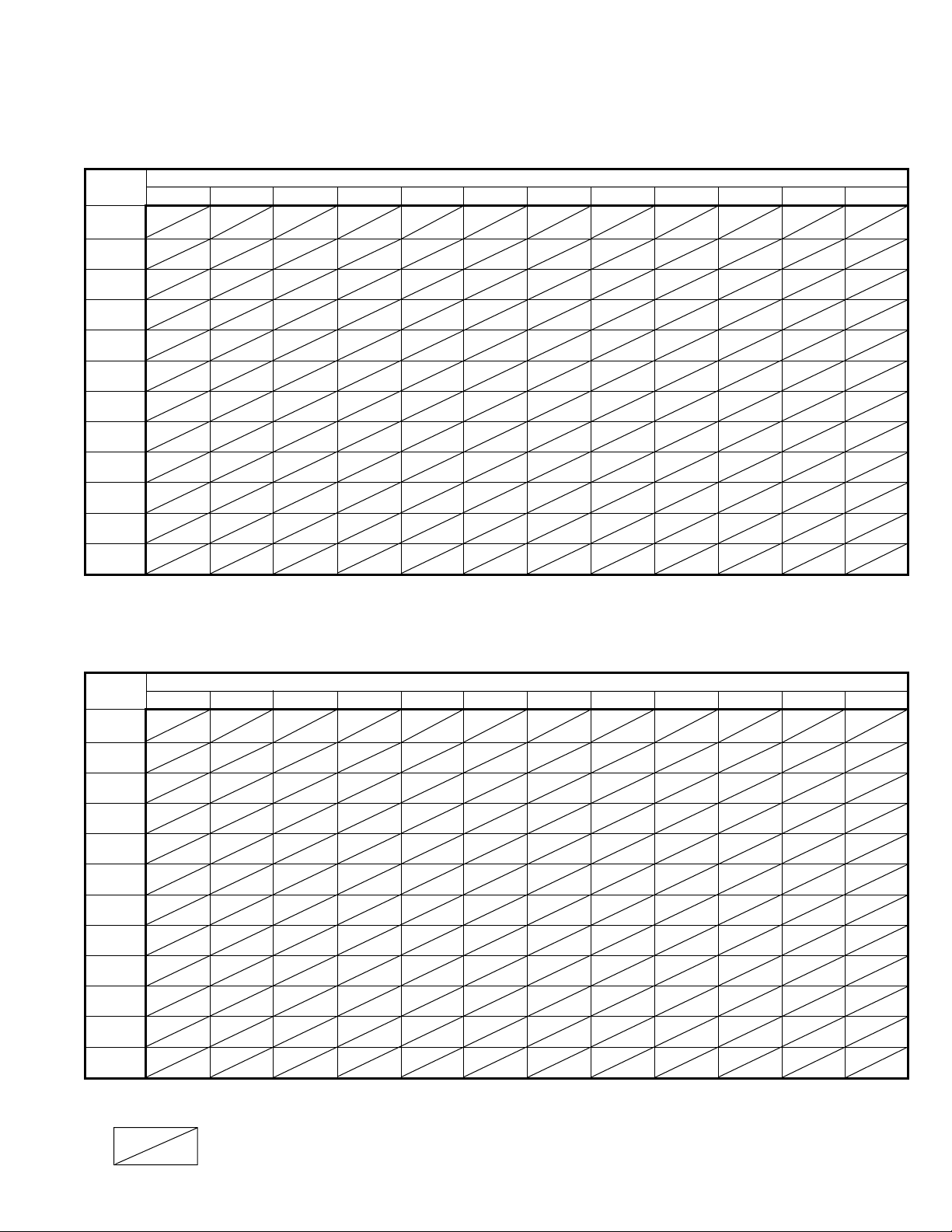
Table 10
Models PV or BV Page Location Index ➀
Series Identity 105
Series Identity 106
➀ Cell format represents single or three phase power as shown in the following example.
1Ph
3Ph
Table 11
Models PV or BV Page Location Index ➀
Control Model Size
Code 30 50 75 100 125 150 175 200 250 300 350 400
11 or 12
13 or 14
30 or 31
27
28
27
28
27
28
27
28
27
28
27
28
27
28
27
28
27
28
27
28
27
28
27
28
32 or 33
37 37 37 37 37 37 37 37 37 37 37
59 or 60
63 or 64
81 or 82
85 or 86
27
28
27
28
27
28
27
28
27
28
27
28
27
28
27
28
27
28
27
28
27
28
27
28
87 or 88
89 or 90
91 or 92
93 or 94
Control Model Size
Code 30 50 75 100 125 150 175 200 250 300 350 400
11 or 12
13 or 14
30 or 31
35
36
35
36
35
36
35
36
35
36
35
36
35
36
35
36
35
36
35
36
35
36
35
36
32 or 33
59 or 60
63 or 64
81 or 82
85 or 86
35
36
35
36
35
36
35
36
35
36
35
36
35
36
35
36
35
36
35
36
35
36
35
36
87 or 88
89 or 90
91 or 92
93 or 94
6-440.2 – WIRING DIAGRAMS MODELS PV/BV
1
Single Phase — 5H73595C1 Rev A
2
6-440.2 – WIRING DIAGRAMS MODELS PV/BV
Three Phase — 5H73595C1 Rev A
3
6-440.2 – WIRING DIAGRAMS MODELS PV/BV
Single Phase — 5H73595C2 Rev A
5H73595C2 Mechanical Modulation, Automatic Electronic Pilot Ignition, 100% Shut-off, with
continuous retry, Single-phase.
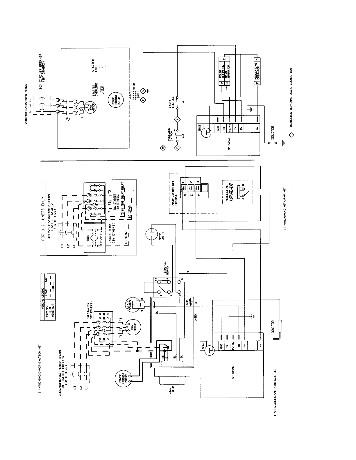
4
6-440.2 – WIRING DIAGRAMS MODELS PV/BV
Three Phase — 5H73595C2 Rev A
5H73595C2 Rev. A Mechanical Modulation, Automatic Electronic Pilot Ignition, 100% Shut-off with
continuous retry, Three-phase.
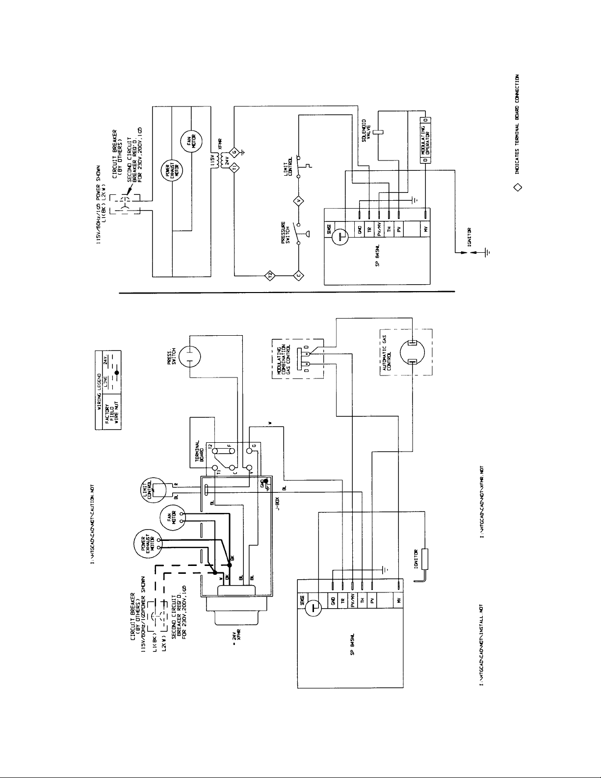
5
6-440.2 – WIRING DIAGRAMS MODELS PV/BV
Single Phase — 5H73595C3 Rev A
5H73595C3 Rev A Mechanical Modulation, Automatic Electronic Pilot Ignition with continuous
retry, Single-phase.
6
6-440.2 – WIRING DIAGRAMS MODELS PV/BV
Three Phase — 5H73595C3 Rev A
5H73595C3 Rev A Mechanical Modulation, Automatic Electronic Pilot Ignition with continuous retry,
Three-phase.
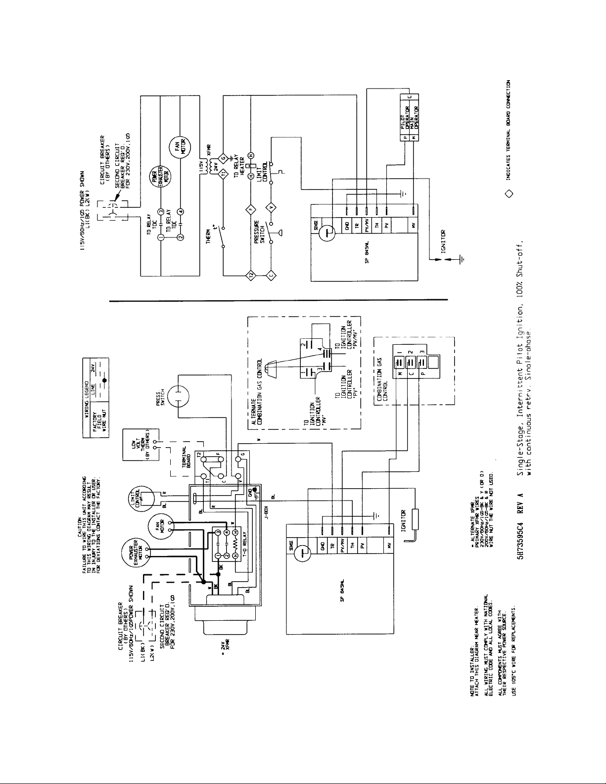
7
6-440.2 – WIRING DIAGRAMS MODELS PV/BV
Single Phase — 5H73595C4 Rev A
8
6-440.2 – WIRING DIAGRAMS MODELS PV/BV
Three Phase — 5H73595C4 Rev A
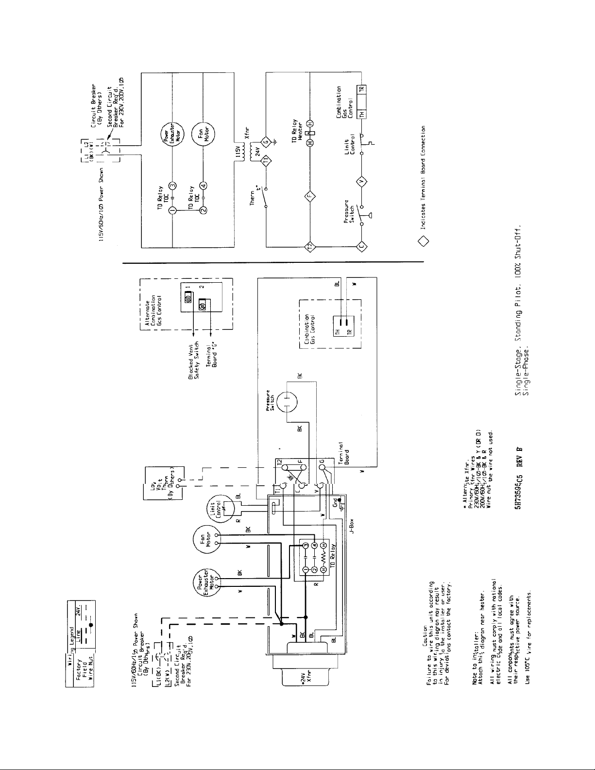
9
6-440.2 – WIRING DIAGRAMS MODELS PV/BV
Single Phase — 5H73595C5 Rev B
10
6-440.2 – WIRING DIAGRAMS MODELS PV/BV
Three Phase — 5H73595C5 Rev C
 Loading...