

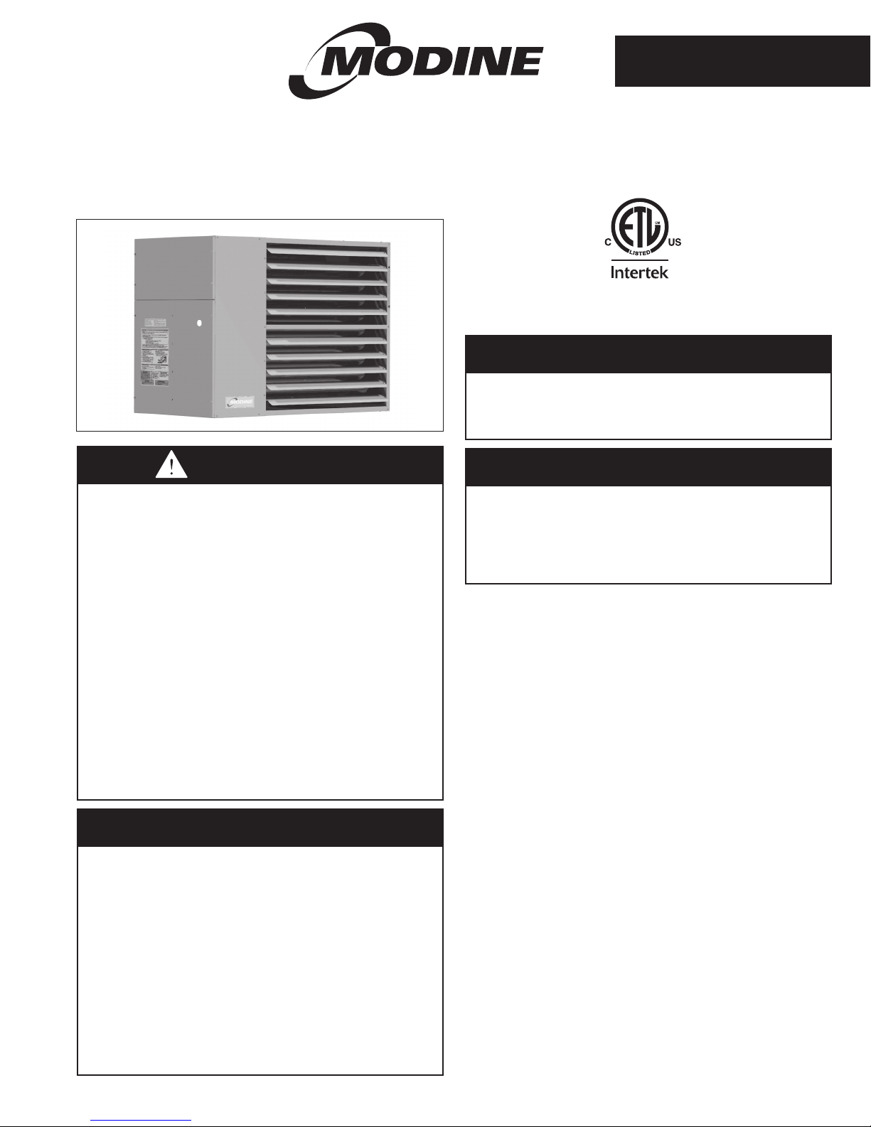
Modine Manufacturing PTP, PTP 150, PTP 175, PTP 200, PTP 250 Service Manual
...
6-560.4
5H0801050000
November, 2014
INSTALLATION AND SERVICE MANUAL
power vented gas-fired unit heaters
model PTP
All models approved for use in California by the CEC and in
Massachusetts. Unit heater is certified for non-residential
applications.
FOR YOUR SAFETY
The use and storage of gasoline or other
flammable vapors and liquids in open containers
in the vicinity of this appliance is hazardous.
W ARNING
1. Improper installation, adjustment, alteration,
service, or maintenance can cause property
damage, injury, or death, and could cause
exposure to substances which have been
determined by various state agencies to
cause cancer, birth defects, or other
reproductive harm. Read the installation,
operating, and maintenance instructions
thoroughly before installing or servicing
this equipment.
2. Do not locate ANY gas-fired units in areas
where chlorinated, halogenated, or acidic
vapors are present in the atmosphere.
These substances can cause premature
heat exchanger failure due to corrosion,
which can cause property damage, serious
injury, or death.
FOR YOUR SAFETY
WHAT TO DO IF YOU SMELL GAS:
1. Open windows.
2. Do not try to light any appliance.
3. Do not touch any electrical switch; do
not use any phone in your building.
4. Extinguish any open flame.
5. Immediately call your gas supplier from
a neighbor’s phone. Follow the gas
supplier’s instructions. If you can not
reach your gas supplier, call your fire
department.
IMPORTANT
The use of this manual is specifically intended
for a qualified installation and service agency.
All installation and service of these units
must be performed by a qualified installation
and service agency.
Inspection on Arrival
1. Inspect unit upon arrival. In case of damage, report it
immediately to transportation company and your local
Modine sales representative.
2.
Check rating plate on unit to verify that power supply meets
available electric power at the point of installation.
3. Inspect unit upon arrival for conformance with description of
product ordered (including specifications where applicable).
Table of Contents
Inspection on Arrival ................................. 1
Special Precautions ................................. 2
SI (Metric) Conversion Factors ........................ 3
Before You Begin . . . . . . . . . . . . . . . . . . . . . . . . . . . . . . . . . . . 3
Unit Location ...................................... 4
Combustible Material and Service Clearances .......... 4
Unit Mounting .................................... 5
Installation ........................................ 6
Venting . . . . . . . . . . . . . . . . . . . . . . . . . . . . . . . . . . . . . . . . . 6
Gas Connections ................................ 10
High-Altitude Accessory Kit .........................11
Electrical Connections ............................ 13
Operation ...................................... 14
Unit Components .................................. 15
Performance Data - General ......................... 15
Performance Data - Downturn Hoods .................. 16
Dimensions....................................... 17
Service/Maintenance/Troubleshooting .................. 18
Model/Serial Number/Replacement Parts ............... 19
Commercial Warranty........................Back Cover
PLEASE BE SURE TO LEAVE IT WITH THE OWNER WHEN YOU LEAVE THE JOB.
THIS MANUAL IS THE PROPERTY OF THE OWNER.
SPECIAL PRECAUTIONS
SPECIAL PRECAUTIONS
THE INSTALLATION AND MAINTENANCE INSTRUCTIONS IN
THIS MANUAL MUST BE FOLLOWED TO PROVIDE SAFE,
EFFICIENT AND TROUBLE-FREE OPERATION. IN ADDITION,
PARTICULAR CARE MUST BE EXERCISED REGARDING THE
SPECIAL PRECAUTIONS LISTED BELOW. FAILURE TO
PROPERLY ADDRESS THESE CRITICAL AREAS COULD
RESULT IN PROPERTY DAMAGE OR LOSS, PERSONAL
INJURY, OR DEATH. THESE INSTRUCTIONS ARE SUBJECT
TO ANY MORE RESTRICTIVE LOCAL OR NATIONAL CODES.
HAZARD INTENSITY LEVELS
1. DANGER: Indicates an imminently hazardous situation
which, if not avoided, WILL result in death or serious injury.
2. WARNING: Indicates a potentially hazardous situation
which, if not avoided, COULD result in death or serious injury.
3. CAUTION: Indicates a potentially hazardous situation which,
if not avoided, MAY result in minor or moderate injury.
4. IMPORTANT: Indicates a situation which, if not avoided,
MAY result in a potential safety concern.
DANGER
Appliances must not be installed where they may be exposed
to a potentially explosive or flammable atmosphere.
ARNING
W
1. Gas fired heating equipment must be vented - do not
operate unvented.
2. A built-in power exhauster is provided - additional external
power exhausters are not required or permitted.
3. If an existing heater is being replaced, it may be necessary
to resize the venting systems. Improperly sized venting
systems can result in vent gas leakage or the formation of
condensate. Refer to the National Fuel Gas Code ANSI
Z223.1 (NFPA 54) or CSA B149.1 - latest edition. Failure
to follow these instructions can result in injury or death.
4. Under no circumstances should two sections of double
wall vent pipe be joined together within one horizontal
vent system due to the inability to verify complete seal of
inner pipes.
5. All field gas piping must be pressure/leak tested prior to
operation. Never use an open flame. Use a soap solution
or equivalent for testing.
6. Gas pressure to appliance controls must never exceed
14" W.C. (1/2 psi).
7. To reduce the opportunity for condensation, the minimum
sea level input to the appliance, as indicated on the serial
plate, must not be less than 5% below the rated input, or
5% below the minimum rated input of dual rated units.
8. Disconnect power supply before making wiring
connections to prevent electrical shock and equipment
damage.
9. All appliances must be wired strictly in accordance with
wiring diagram furnished with the appliance. Any wiring
different from the wiring diagram could result in a hazard
to persons and property.
10. Any original factory wiring that requires replacement must
be replaced with wiring material having a temperature
rating of at least 105°C.
11. Ensure that the supply voltage to the appliance, as
indicated on the serial plate, is not 5% greater than the
rated voltage.
W ARNING
12. When servicing or repairing this equipment, use only
factory-approved service replacement parts. A complete
replacements parts list may be obtained by contacting
the factory. Refer to the rating plate on the appliance for
complete appliance model number, serial number, and
company address. Any substitution of parts or controls not
approved by the factory will be at the owner's risk.
CAUTION
1. All literature shipped with this unit should be kept for
future use for servicing or service diagnostics. Do not
discard any literature shipped with this unit.
2. Consult piping, electrical, and venting instructions in this
manual before final installation.
3. Do not attach ductwork, air filters, or polytubes to any
propeller unit heater.
4. Clearances to combustible materials are critical. Be sure
to follow all listed requirements.
5. Heaters are designed for use in heating applications with
ambient startup temperatures between -40°F and 90°F,
and ambient operating temperatures between 40°F
and 90°F.
6. Do not install unit outdoors.
7. In garages or other sections of aircraft hangars such as
offices and shops that communicate with areas used for
servicing or storage, keep the bottom of the unit at least
7' above the floor unless the unit is properly guarded to
provide user protection from moving parts. In parking
garages, the unit must be installed in accordance with the
standard for parking structures ANSI/NFPA 88A - latest
edition, and in repair garages the standard for repair
garages NFPA 30A - latest edition (formerly NFPA 88B).
In Canada, installation of heaters in airplane hangars
must be in accordance with the requirements of the
enforcing authority, and in public garages in accordance
with the current CSA-B149 codes.
8. In aircraft hangars, keep the bottom of the unit at least 10'
from the highest surface of the wings or engine enclosure
of the highest aircraft housed in the hangars and in
accordance with the requirements of the enforcing
authority and/or NFPA 409 - latest edition.
9. Installation of units in high humidity or salt water
atmospheres will cause accelerated corrosion, resulting in
a reduction of the normal life of the units.
10. Do not install units below 7' measured from the bottom of
the unit to the floor in commercial applications (unless unit
is properly guarded to provide user protection from
moving parts).
11. Be sure no obstructions block air intake and discharge of
unit heaters.
12. The minimum distance from combustible material is based
on the combustible material surface not exceeding 160°F.
Clearance from the top of the unit may be required to be
greater then the minimum specified if heat damage, other
than fire, may occur to materials above the unit heater at
the temperature described.
13. Allow 18" of clearance at rear (or 12" beyond end of
motor at rear of unit, whichever is greater) and access
side to provide ample air for proper operation of fan.
14. Installation must conform with local building codes or in
the absence of local codes, with the National Fuel Gas
Code, ANSI Z223.1 (NFPA 54) - latest edition. In Canada
installation must be in accordance with CSA-B149.1.
2
6-560.4
SPECIAL PRECAUTIONS / SI (METRIC) CONVERSION FACTORS
BEFORE YOU BEGIN
CAUTION
15. Purging of air from gas supply line should be performed
as described in the National Fuel Gas Code, ANSI Z223.1
(NFPA 54) - latest edition. In Canada, installation must be
in accordance with CSA-B149.1.
16. When leak testing the gas supply piping system, the
appliance and its combination gas control must be
isolated during any pressure testing in excess of 14" W.C.
(1/2 psi).
17. The unit should be isolated from the gas supply piping
system by closing its field installed manual shut-off valve.
This manual shut-off valve should be located within 6' of
the heater.
18. Turn off all gas before installing appliance.
19. Ensure that the supply voltage to the appliance, as
indicated on the serial plate, is less than 5% below the
rated voltage.
20. Check the gas inlet pressure at the unit upstream of the
combination gas control. The inlet pressure should be
6-7" W.C. on natural gas or 12-14" W.C. on propane. If
inlet pressure is too high, install an additional pressure
regulator upstream of the combination gas control.
21. Service or repair of this equipment must be performed by
a qualified service agency.
22. Do not attempt to reuse any mechanical or electronic
ignition controller which has been wet. Replace defective
controller.
IMPOR T ANT
1. To prevent premature heat exchanger failure, do not locate
ANY gas-fired appliances in areas where corrosive vapors
(i.e. chlorinated, halogenated, or acidic) are present in the
atmosphere.
2. To prevent premature heat exchanger failure, the input to
the appliance as indicated on the serial plate, must not
exceed the rated input by more than 5%.
3. Start-up and adjustment procedures must be performed
by a qualified service agency.
1. All literature shipped with this unit should be kept for future
use for servicing or service diagnostics. Leave manual with
the owner. Do not discard any literature shipped with this unit.
2. Consult piping, electrical, and venting instructions in this
manual before final installation.
3. Do not attach ductwork, air filters, or polytubes to any
propeller unit heater.
In the U.S., the installation of these units must comply with the
National Fuel Gas Code, ANSI Z223.1 (NFPA 54) - latest edition
and other applicable local building codes. In Canada, the
installation of these units must comply with local plumbing or
waste water codes and other applicable codes and with the
current code CSA-B149.1.
1. All installation and service of these units must be
performed by a qualified installation and service agency
only as defined in ANSI Z223.1 (NFPA 54) - latest edition or
in Canada by a licensed gas fitter.
2. This unit is certified with the controls furnished. For
replacements parts, please order according to the
replacement parts list on serial plate. Always know your
model and serial numbers. Modine reserves the right to
substitute other authorized controls as replacements.
3. Unit is balanced for correct performance. Do not alter fan
or operate motors at speeds below what is shown in this
manual.
4. Information on controls is supplied separately.
5. The same burner is used for natural and propane gas.
SI (Metric) Conversion Factors
To Convert Multiply By To Obtain
°F (°F-32) x 5/9 °C
BTU 1.06 kJ
Btu/ft
Btu/hr 0.000293 kW
CFH (ft
CFH (ft
CFM (ft
CFM (ft
feet 0.305 m
Gal/Hr. 0.00379 m
Gal/Hr. 3.79 l/hr
gallons 3.79 l
Horsepower 746 W
inches 25.4 mm
pound 0.454 kg
psig 6.89 kPa
psig 27.7 "W.C.
"W.C. 0.249 kPa
3
3
3
/min) 0.0283 m3/min
3
/min) 0.000472 m3/s
CAUTION
3
37.3 kJ/m
/hr) 0.000472 m3/min
/hr) 0.00000787 m3/s
3
3
/hr
6-560.4
3
UNIT LOCATION
UNIT LOCATION
DANGER
Appliances must not be installed where they may be
exposed to a potentially explosive or flammable atmosphere.
CAUTION
1. Clearances to combustible materials are critical. Be sure to
follow all listed requirements.
2. Heaters are designed for use in heating applications with
ambient startup temperatures between -40°F and 90°F,
and ambient operating temperatures between 40°F and 90°F.
3. Do not install unit outdoors.
4. In garages or other sections of aircraft hangars such
as offices and shops that communicate with areas used for
servicing or storage, keep the bottom of the unit at least
7' above the floor unless the unit is properly guarded.
In parking garages, the unit must be installed in accordance
with the standard for parking structures ANSI/NFPA 88A -
latest edition, and in repair garages the standard for repair
garages NFPA 30A - latest edition (formerly NFPA 88B).
In Canada, installation of heaters in airplane hangars must
be in accordance with the requirements of the enforcing
authority, and in public garages in accordance with the
current CSA-B149 codes.
5. In aircraft hangars, keep the bottom of the unit at least
10' from the highest surface of the wings or engine
enclosure of the highest aircraft housed in the hangars
and in accordance with the requirements of the enforcing
authority and/or NFPA 409 - latest edition.
6. Installation of units in high humidity or salt water
atmospheres will cause accelerated corrosion resulting in
a reduction of the normal life of the units.
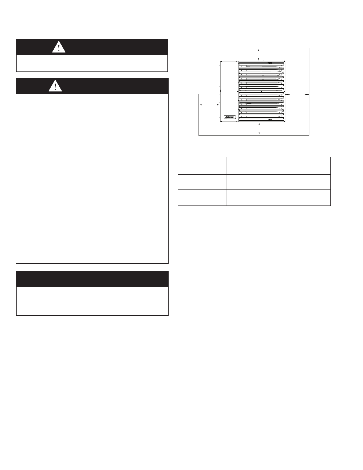
Figure 4.1 - Combustible Material and Service
Clearances
TOP
NON
ACCESS
SIDE
BOTTOM
ACCESS
SIDE
Table 4.1 - Clearances
Unit Side
Combustible Materials Service Clearance
Top and Bottom 6" 6"
Access Side 6" 18"
Non-Access Side 6" 6"
Rear 18" 18"
Vent Connector 6" 6"
6. Do not install units in locations where gas ignition system is
exposed to water spray, rain, or dripping water.
7. Mounting height (measured from bottom of unit) at which unit
heaters are installed is critical. Refer to mounting height and
heat throw data on page 15 of this manual. The maximum
mounting height for any unit is that height above which the
unit will not deliver heated air to the floor.
Clearance To Recommended
IMPOR T ANT
To prevent premature heat exchanger failure, do not locate
ANY gas-fired appliances in areas where corrosive vapors
(i.e. chlorinated, halogenated or acidic) are present in the
atmosphere.
Location Recommendations
1. When locating the heater, consider general space and
heating requirements, availability of gas and electrical supply,
and proximity to vent locations.
2. When locating units, it is important to consider that the
exhaust vent piping must be connected to the outside
atmosphere. Maximum equivalent vent lengths are listed in
“Section A - General Instruction - All Units” of the Venting
instructions.
3. Be sure the structural support at the unit location site is
adequate to support the unit's weight. Refer to page 17 for
unit weights. For proper operation the unit must be installed
in a level horizontal position.
4. Do not install units in locations where the flue products
can be drawn into the adjacent building openings such as
windows, fresh air intakes, etc.
5. Be sure that the minimum clearances to combustible
materials and recommended service clearances are
maintained. Units are designed for installation with the
minimum clearances as shown in Figure 4.1 and Table 4.1.
Combustion Air Requirements
The National Fuel Gas Code defines an “unconfined space” as
a space whose volume is greater than 50 cubic feet per 1,000
Btu/Hr input of the installed appliance(s). A confined space is
50 cubic feet or less per 1,000 Btu/Hr input of the installed
appliance(s).
Units installed in tightly sealed buildings or confined spaces
must be provided with 2 permanent openings - 1 near the top
and 1 near the bottom of the confined space. Each opening
should have a free area of not less than one square inch per
1,000 Btu/Hr of the total input rating of all units in the confined
space, freely communicating with interior areas that have
adequate infiltration from the outside.
For further details on supplying combustion air to a confined
(tightly sealed) space or unconfined space, see the National
Fuel Gas Code ANSI Z223.1 (NFPA 54) or CSA-B149.1
Installation Code - latest edition.
Sound and Vibration Levels
All standard mechanical equipment generates some sound and
vibration that may require attenuation. Libraries, private offices
and hospital facilities will require more attenuation, and in such
cases, an acoustical consultant may be retained to assist in the
application. Locating the equipment away from the critical area
is desirable within ducting limitations. Generally, a unit should
be located within 15' of a primary support beam. Smaller
deflections typically result in reduced vibration and noise
transmission.
4
6-560.4
UNIT MOUNTING
CAUTION
1. Do not install units below 7' measured from the bottom of
the unit to the floor in commercial applications (unless
unit is properly guarded to provide user protection from
moving parts).
2. Be sure no obstructions block air intake and discharge
of unit heaters.
3. The minimum distance from combustible material is
based on the combustible material surface not exceeding
160°F. Clearance from the top of the unit may be required
to be greater than the minimum specified if heat damage,
other than fire, may occur to materials above the unit
heater at the temperature described.
4. Allow 18" clearance at rear (or 12" beyond end of motor
at rear of unit, whichever is greater) and access side to
provide ample air for proper operation of fan.
1. Be sure the means of suspension is adequate to support
the weight of the unit (see page 17 for unit weights).
2. For proper operation, the unit must be installed in a level
horizontal position.
3. Clearances to combustibles as specified in Table 4.1 must be
strictly maintained.
4. All standard units are shipped fully boxed. Larger units are
also supplied with skid supports on the bottom of the box.
The larger units may be lifted from the bottom by means of a
fork lift or other lifting device only if the shipping support skids
are left in place and the forks support the whole depth of the
unit. If the unit must be lifted from the bottom for final
installation without the carton in place, be sure to properly
support the unit over its entire length and width to prevent
damage. When lifting units, make sure the load is balanced.
5. Propeller models have 4 mounting holes.The units can be
mounted with 3/8"-16 threaded rod as follows:
•Oneachpieceofthreadedrodused,screwanutadistance
of about 1" onto the end of the threaded rods that will be
screwed into the unit heater.
•Placeawasherovertheendofthethreadedrodandscrew
the threaded rod into the unit heater weld nuts on the top of
the heater at least 5 turns, and no more than 10 turns.
Tighten the nut first installed onto the threaded rod to
prevent the rod from turning.
•Drillholesintoasteelchannelorangleironatthesame
center-line dimensions as the heater that is being installed.
The steel channels or angle iron pieces need to span and
be fastened to appropriate structural members.
•Cutthethreadedrodstothepreferredlength,placethem
through the holes in the steel channel or angle iron and
secure with washers and lock nuts or lock washers and
nuts. A double nut arrangement can be used here instead of
at the unit heater (a double nut can be used both places but
is not required).
•Donotinstallstandardunitheatersabovethemaximum
mounting height shown in Table 15.1.
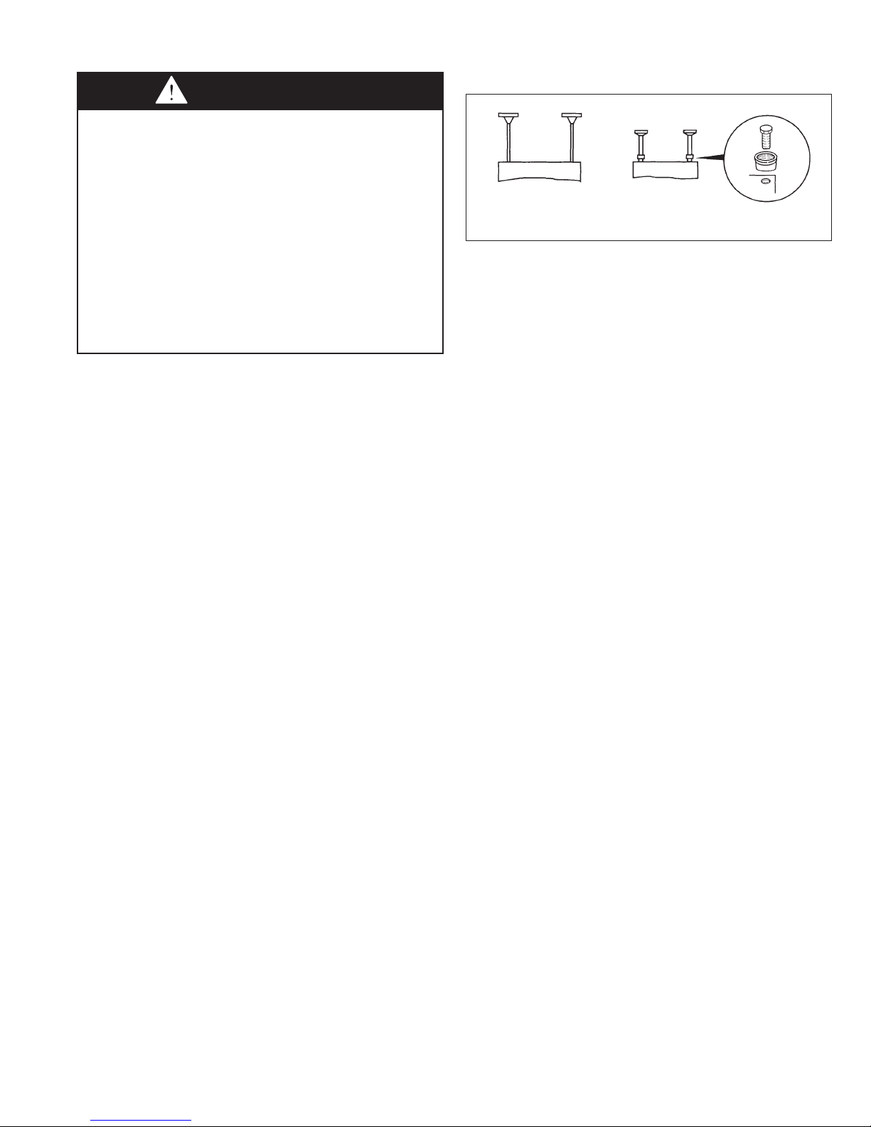
NOTE: A pipe hanger adapter kit, shown in Figure 5.1 is
available as an accessory. One kit consists of two drilled 3/4"
IPS pipe caps and two 3/8"-16 x 1-1/2" capscrews to facilitate
threaded pipe suspension. Two kits would be required for
PTP units.
Figure 5.1 - Unit Heater Suspension Methods
(Threaded Rod) (Pipe Adapter Kit)
6-560.4
5
INSTALLATION - VENTING
W ARNING
1. Gas fired heating equipment must be vented - do not
operate unvented.
2. A built-in power exhauster is provided - additional external
power exhausters are not required or permitted.
3. If an existing heater is being replaced, it may be
necessary to resize the venting systems. Improperly sized
venting systems can result in vent gas leakage or the
formation of condensate. Refer to the National Fuel Gas
Code ANSI Z223.1 (NFPA 54) or CSA B149.1 - latest
edition. Failure to follow these instructions can result in
serious injury or death.
4. Under no circumstances should 2 sections of double wall
vent pipe be joined together within 1 horizontal vent
system due to the inability to verify complete seal of inner
pipes.
CAUTION
Installation must conform with local building codes or in the
absence of local codes, with Part 7, Venting of Equipment, of
the National Fuel Gas Code, ANSI Z223.1 (NFPA 54) - latest
edition. In Canada installation must be in accordance with
CSA B149.1.
Model PTP unit heaters must be vented with the proper
passageway as described in these instructions to convey flue
gases from the unit or the vent connector to the outside
atmosphere.
The venting instructions are organized in sections, based on
installation type. The sections are identified as follows:
Instructions
A General Instructions for ALL Installations
B VERTICAL CATEGORY I vent systems ➀
C HORIZONTAL CATEGORY III vent systems ➀
ThedifferencesbetweenVerticalandHorizontalventsystemswillbeidentied
in "Section A - General Instructions - All Units".
Applicable Installation Instructions
by Vent System Type
A4. Refer to Table 6.1 for total minimum and maximum vent
lengths, making the system as straight as possible. The
equivalent length of a 90° elbow is 5 feet for 4 inch
diameter and 7 feet for 6 inch diameter.
Table 6.1 - Vent Pipe Diameters, Transitions, and
Total Equivalent Vent Pipe Lengths for Horizontal
Venting Systems
Model
Size
150 4" 3' 50'
175-200 4" 3' 70'
250-400 6" 3' 70'
A5. Horizontal sections of vent pipe are to be installed with a
Vent Pipe
Diameter
minimum downward slope from the appliance of 1/4 inch
per foot and suspended securely from overhead structures
at points not greater than 3' apart.
A6. Fasten individual lengths of vent together with at least 3
corrosion-resistant sheet metal screws.
A7. Keep single wall vent pipe at least 6" from combustible
materials. For double wall vent pipe, follow the vent pipe
manufacturer’sclearancestocombustibles.Theminimum
distance from combustible materials is based on the
combustible material surface not exceeding 160°F.
Clearance from the vent pipe (or the top of the unit) may be
required to be greater than 6" if heat damage other than fire
could result (such as material distortion or discoloration).
A8. Avoid venting through unheated space when possible.
When venting does pass through an unheated space or if
the unit is installed in an environment that promotes
condensation, insulate runs greater than 5' to minimize
condensation. Inspect for leakage prior to insulating and
use insulation that is noncombustible with a rating of not
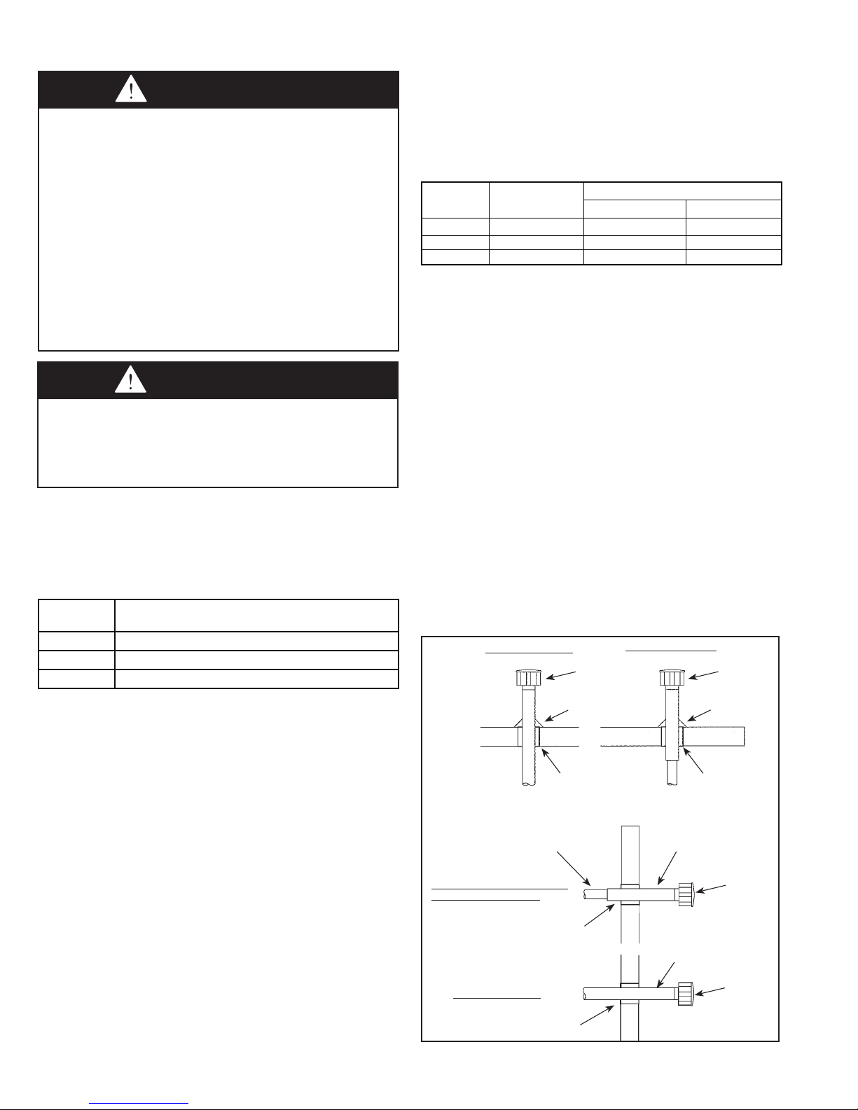
less than 400°F. Install a tee fitting at the low point of the
vent system and provide a drip leg with a clean out cap as
shown in Figure 8.1.
Equivalent Vent Length
Minimum Maximum
Figure 6.1 - Venting Through Combustible Roof
or Wall
Single Wall Vent Pipe
Specified
Terminal
Flashing
Double Wall Vent Pipe
Flashing
Specified
Terminal
Section A - General Instructions - All Units
A1. If the unit heater being installed is replacing existing
equipment and using the existing vent system from that
equipment, inspect the venting system for proper size and
horizontal pitch, as required in the National Fuel Gas Code,
ANSI Z223.1 (NFPA 54) or CSA B149.1 Installation Code latest edition and these instructions. Determine that there is
no blockage or restriction, leakage, corrosion and other
deficiencies, which could cause an unsafe condition.
A2. The vent pipe should be galvanized steel or other suitable
corrosion-resistant material. Follow the National Fuel Gas
Code for minimum thickness of vent material. The minimum
thickness for connectors varies depending on the pipe
diameter. Do not vent unit with PVC or other forms of
plastic venting material.
A3. All heaters come with a factory installed vent adapter for
attaching the vent pipe to the heater (see Table 6.1). Attach
the vent pipe to the adapter with 3-corrosion resistant
screws. (Drill pilot holes through the vent pipe and adapter
prior to screwing in place). Vent pipe must not be smaller
than the connector size.
6
Listed
Thimble
Single
Wall
Single Wall Vent Pipe Terminating
with Double wall vent pipe.
Clearance Specified
by Type B Vent Mfg.
Single Wall Vent Pipe
Listed
Thimble
See Instruction A12 for attaching single wall pipe to double wall pipe
6-560.4
Clearance Specified
by Type B Vent Mfg.
Double
Wall
Specified
Terminal
Single
Wall
Specified
Terminal
 Loading...