

Modine Manufacturing VE, PTE Service Manual
2-506.14
5H605869
January, 2013
INSTALLATION AND SERVICE MANUAL
electric unit heaters
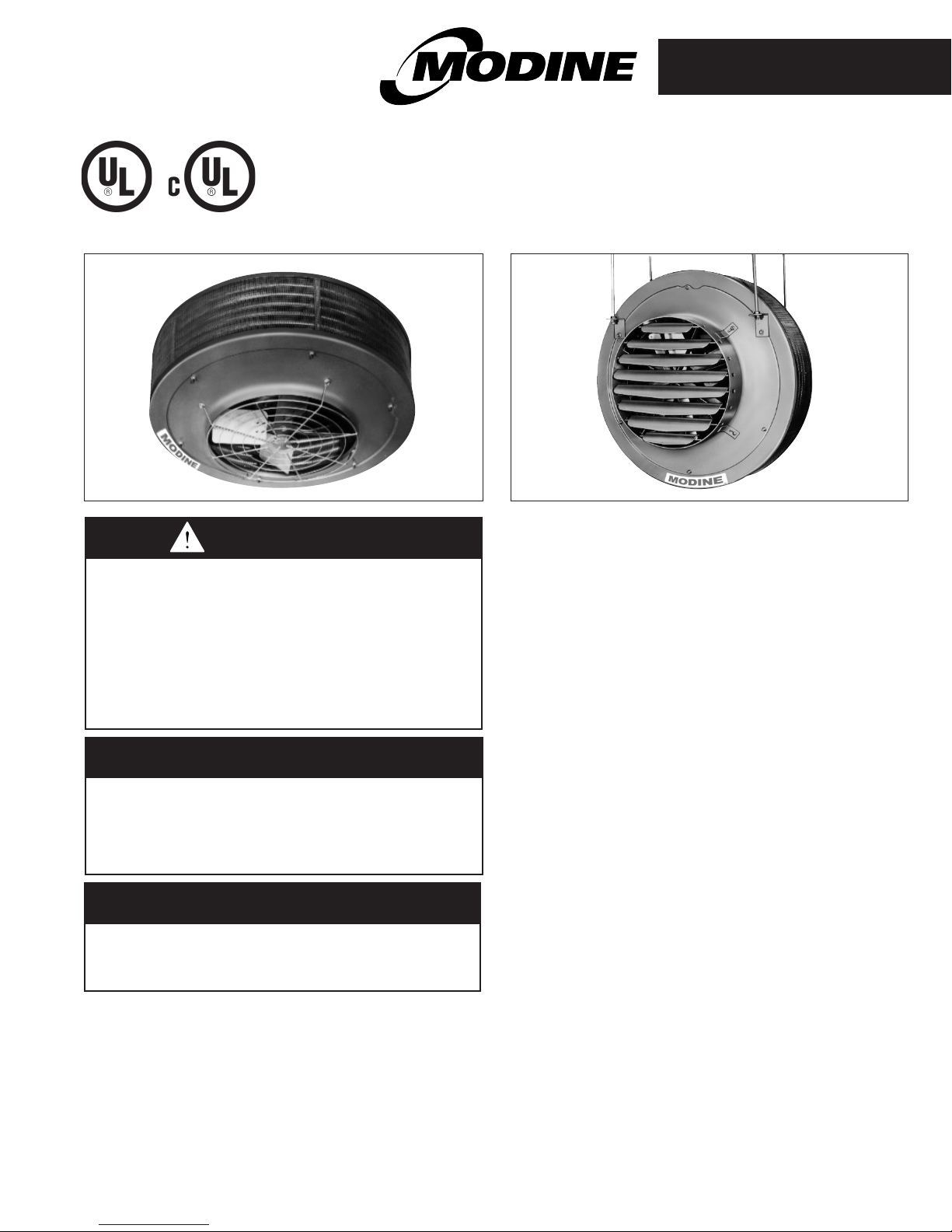
models VE and PTE
Model PTEModel VE
WARNING
Improper installation, adjustment, alteration,
service or maintenance can cause property
damage, injury or death, and could cause
exposure to substances which have been
determined by various state agencies to cause
cancer, birth defects or other reproductive
harm. Read the installation, operating and
maintenance instructions thoroughly before
installing or servicing this equipment.
IMPORTANT
The use of this manual is specifically intended
for a qualified installation and service agency.
A qualified installation and service agency
must perform all installation and service of
these appliances.
FOR YOUR SAFETY
The use and storage of gasoline or other
flammable vapors and liquids in open containers
in the vicinity of this appliance is hazardous.
Inspection On Arrival
1. Inspect unit upon arrival. In case of damage, report
immediately to transportation company and your local
Modine sales representative.
2. Check rating plate on unit and motor to verify that power
supply and motor specification requirements meet available
electric power at the point of installation.
3. Inspect unit received for conformance with description of
product ordered (including specifications where applicable).
General Information
Installation and wiring of these electric unit heaters must conform
to all applicable local codes and the National Electric Code.
Wiring of these electric unit heaters should only be performed by
a qualified electrician.
These electric unit heaters are Listed by Underwriters
Laboratories, Inc. Representative samples of this product
have been evaluated by UL and meet the applicable U.S. and
Canadian safety standards with components as furnished.
All replacement parts and controls are proprietary in that they
have all been designed, tested, and approved for the particular
application to insure both physical fit and electrical performance.
Any substitution of parts or controls not approved by Modine will
be at installer’s risk. For replacement parts, submit the unit
heater model number, power code, control code and serial
number shown on the rating plate attached to the unit.
Do not remove outlet fan guard from vertical electric unit heaters
except to service the unit.
Contents
General Information ................................1
Installation
Special Precautions / Important Instructions..........2
Unit Locations ................................3
Ceiling Suspension ...........................4-5
Wall Mounting Bracket ..........................5
Dimensional/Performance Data ...................6
Motor Specifications . . . . . . . . . . . . . . . . . . . . . . . . . . . .6
Wiring Instructions/Data .......................7-8
Operation
Prior to Operation . . . . . . . . . . . . . . . . . . . . . . . . . . . . . .9
Initial Start-up .................................9
General Maintenance ..............................10
Troubleshooting ..................................11
Warranty........................................12
THIS MANUAL IS THE PROPERTY OF THE OWNER.
PLEASE BE SURE TO LEAVE IT WITH THE OWNER WHEN YOU LEAVE THE JOB.
SPECIAL PRECAUTIONS / IMPORTANT INSTRUCTIONS
SPECIAL PRECAUTIONS / IMPORTANT
INSTRUCTIONS
THE INSTALLATION AND MAINTENANCE INSTRUCTIONS IN THIS
MANUAL MUST BE FOLLOWED TO PROVIDE SAFE, EFFICIENT AND
TROUBLE-FREE OPERATION. IN ADDITION, PARTICULAR CARE
MUST BE EXERCISED REGARDING THE SPECIAL PRECAUTIONS
LISTED BELOW. FAILURE TO PROPERLY ADDRESS THESE
CRITICAL AREAS COULD RESULT IN PROPERTY DAMAGE OR LOSS,
PERSONAL INJURY, OR DEATH. THESE INSTRUCTIONS SUBJECT
TO ANY MORE RESTRICTIVE LOCAL OR NATIONAL CODES.
HAZARD INTENSITY LEVELS
1. DANGER: Indicates an imminently hazardous situation
which, if not avoided, WILL result in death or serious injury.
2. WARNING: Indicates a potentially hazardous situation which,
if not avoided, COULD result in death or serious injury.
3. CAUTION: Indicates a potentially hazardous situation which,
if not avoided, MAY result in minor or moderate injury.
4. IMPORTANT: Indicates a situation which, if not avoided,
MAY result in a potential safety concern.
DANGER
Appliances must not be installed where they may be
exposed to a potentially explosive or flammable atmosphere.
1. All literature shipped with this unit should be kept for future
use for servicing or service diagnostics. Do not discard any
literature shipped with this unit.
2. Be sure no obstructions block air intake or discharge of
the appliance.
3. Do not install appliance outdoors.
4.
Do not install VE type unit heaters closer than 18 inches from
ceiling and 24 inches horizontally from combustible materials in
any direction. PTE units must be at least 24 inches from ceiling
and 18 inches horizontally from nearest enclosure. The bottom
of the unit must be at least 8 feet above the floor.
5. The bottom of the appliance must be at least 8 feet above
the floor.
6. Do not attach duct work, air filters, or polytubes to any
appliance.
7. Ensure that the supply voltage to the appliance, as
indicated on the serial plate, is not 5% less than the rated
voltage.
8. Do not reuse any electrical component which has been
wet. Such component must be replaced.
9.
SAVE THESE INSTRUCTIONS
CAUTION
WARNING
1. Disconnect power supply before making wiring connections
to prevent electrical shock and equipment damage.
2. All appliances must be wired strictly in accordance with
wiring diagram furnished with the appliance. Any wiring
different from the wiring diagram could result in a hazard
to persons and property.
3. Ensure that the supply voltage to the appliance, as
indicated on the serial plate, is not 5% greater than the
rated voltage.
4. When servicing or repairing this equipment, use only
factory-approved service replacement parts. A complete
replacement parts list may be obtained by contacting
Modine Manufacturing Company. Refer to the rating plate
on the appliance for complete appliance model number,
serial number, and company address. Any substitution of
parts or controls not approved by the factory will be at
the owner's risk.
5. Do not operate any heater if it malfunctions. Disconnect
power at service panel and have heater inspected by a
qualified installation and service agency.
IMPORTANT
To check most of the Possible Remedies in the troubleshooting
guide listed in Table 9.1, refer to the applicable sections of
the manual.
SI (METRIC) CONVERSION FACTORS
To Convert Multiply By To Obtain
"W.C. 0.249 kPa
°F (°F-32) x 5/9 °C
Btu 1.06 kJ
Btu/ft3 37.3 kJ/m
Btu/hr 0.000293 kW
CFH (ft3/hr) 0.000472 m3/min
CFH (ft3/hr) 0.00000787 m3/s
CFM (ft3/min) 0.0283 m3/min
CFM (ft3/min) 0.000472 m3/s
To Convert Multiply By To Obtain
feet 0.305 m
Gal/Hr. 0.00379 m3/hr
Gal/Hr. 3.79 l/hr
3
gallons 3.79 l
Horsepower 746 W
inches 25.4 mm
pound 0.454 kg
psig 6.89 kPa
psig 27.7 "W.C.
2
2-506.14
INSTALLATION
Locating Unit Heaters
In locating heaters, consider general space-heating requirements
of the area. Unit heaters should be located so that exposed walls
are blanketed with warm air. In multiple unit installations, arrange
units so that the air discharge pattern of one unit overlaps the next
unit thus encompassing the area (See Fig. 3.1 & 3.2). Interference
of air streams by columns, beams, partitions or other obstructions
should be avoided as much as possible.
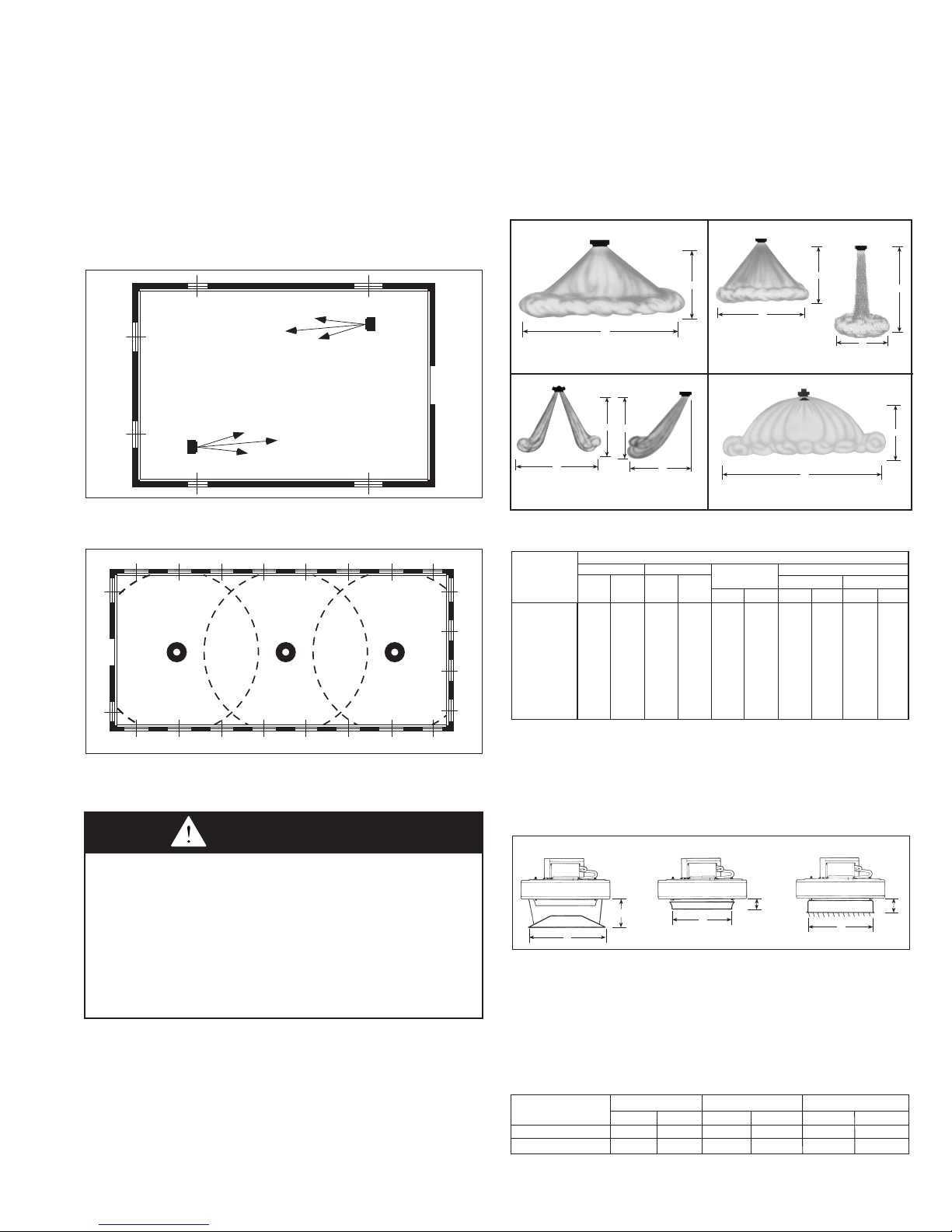
Figure 3.1 - Typical Unit Locations for Horizontal
Air Delivery
If necessary, select the correct deflector assembly to
accommodate the area being covered. Note the louver deflector
data in the table is listed with louvers fully open and with
adjusting vanes set at a 45-degree angle. For these deflectors,
vane adjustment provides a greater spread but requires a lower
mounting height. As indicated, truncone deflectors allow the
lowest mounting height and provide the widest heat spread.
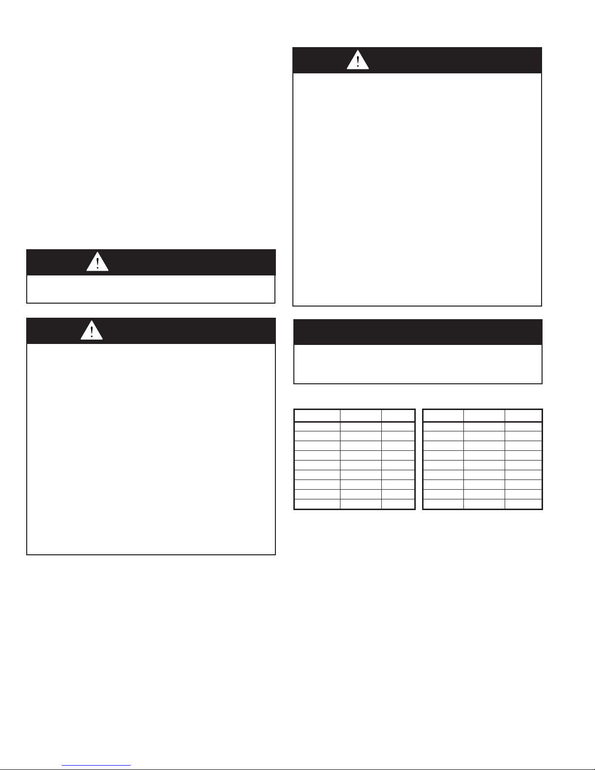
Figure 3.3 - Vertical Delivery Heat Spread/Throw
H
S
S
WITH CONE-JETWITHOUT DEFLECTOR
H
H
H
S
H
H
Figure 3.2 - Typical Unit Locations for Vertical Delivery
Unit Mounting
CAUTION
1.
Do not install VE type unit heaters closer than 18 inches from
ceiling and 24 inches horizontally from combustible materials in
any direction. PTE units must be at least 24 inches from ceiling
and 18 inches horizontally from nearest enclosure. The bottom
of the unit must be at least 8 feet above the floor.
2. The bottom of the appliance must be at least 8 feet above
the floor.
3. Do not attach duct work, air filters, or polytubes to any
appliance.
Height at which unit heaters are installed is critical. Maximum
mounting heights for vertical units are listed in Table 3.1.
Maximum mounting heights for PTE units are listed in
Figure 4.2. The maximum mounting height for any unit is that
height above which the unit will not deliver heated air to the floor.
The maximum mounting heights must not be exceeded in order
to assure maximum comfort.
T
WITH LOUVERS
Table 3.1 - Maximum Mounting Heights/Spreads (feet)
Vertical Delivery
No Deflector Truncone Cone Jet Louvers
Model Blades Open Blades Open Blades 45°
H S H S H S H S H S
VE50 13 20 9 24 18 23 15 13 8 23
VE75 11 17 8 20 15 20 13 11 8 20
VE100 12 18 8 22 17 22 14 12 8 22
VE150 17 26 11 30 23 30 20 17 10 30
VE200 20 30 13 36 27 35 23 20 12 35
VE250 17 26 11 31 23 31 20 18 10 31
VE300 20 31 15 36 28 36 24 21 12 36
VE400 18 27 13 32 24 32 21 18 11 32
VE500 16 24 12 29 22 29 19 16 10 29
➀ The maximum mounting heights consider air delivery to be from the bottom of
the unit to the floor based on conditions in Table 6.2. Refer to Figure 3.3.
T
S
WITH TRUNCONE
➀
It is recommended that adequate service access in excess of
18 inches be provided for the motor and fan.
Figure 3.4 - Vertical Deflector Dimensions
TRUNCONE CONE-JET LOUVERS
M
X
T
L
Z
P
If an optional air deflector has been furnished for vertical units it is
always shipped separately and may be attached to the unit before
suspension. Louvers on horizontal units may also be added
and positioned before installation. Refer to the latest revision of
75-550 for installation instructions for the optional air deflector
assemblies.
Table 3.2 - Vertical Deflector Dimensions (inches)
Model Truncone Cone-Jet Louvers
No. M X L T P Z
VE50-VE250 12 1/2 22 6 1/2 18 7/8 6 1/2 16 7/8
VE300-VE-500 12 1/2 27 7 1/2 24 3/4 7 1/2 19 3/4
2-506.14
3
INSTALLATION
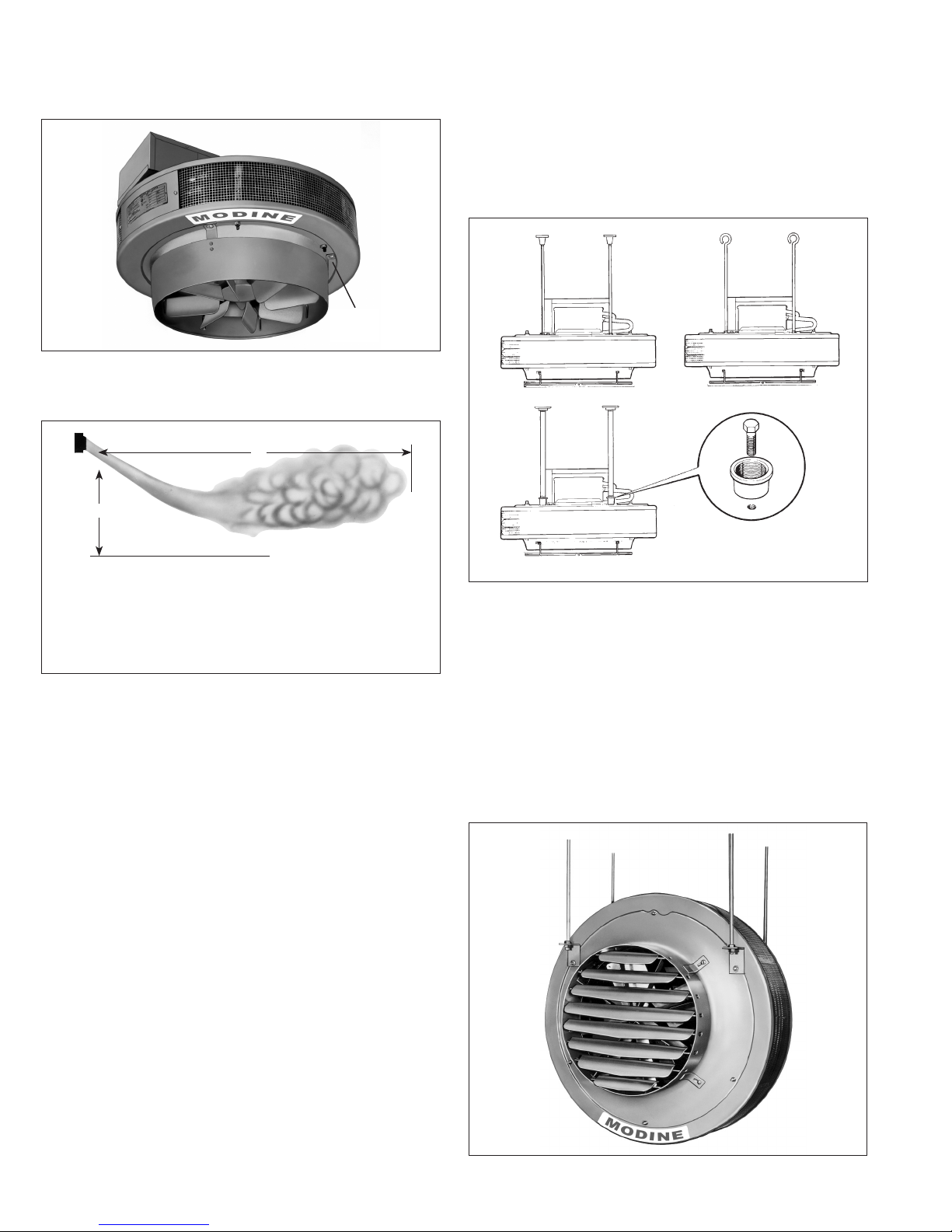
Figure 4.1 - Vertical Model VE with Cone Jet
Accessory Installed
ANGLE
BRACKET
FASTENING
Figure 4.2 - Horizontal Delivery with Louver Deflectors
(Models PTE300, PTE400, PTE500)
T
H
Model VE Unit Suspension
There are four tapped holes (1/2''-13) in the top of the unit for
unit suspension. Unit suspension can be made with threaded
rods, pipes, or ceiling hanger brackets furnished by others.
See Figure 4.3.
Figure 4.3 - Unit Suspension Method of Vertical
Delivery Units
MODEL HEIGHT (H) THROW (T)
PTE300 17 75
PTE400 15 60
PTE500 14 45
Be sure the means of suspension is adequate to support
the weight of the unit. For proper operation, the unit must
be installed in a level horizontal position. Clearances to
combustibles as specified above must be strictly maintained.
Do not install unit heater above the maximum mounting height
shown in Table 3.1 for VE models or Figure 3.4 for PTE models
or below eight feet.
NOTE: A pipe hanger adapter kit is available as an accessory
from Modine. The kit consists of two drilled 3/4'' I.P.S. pipe caps
and two 1/2''-13 x 1 3/4'' capscrews to facilitate threaded-pipe
suspension. Two kits are required to pipe-mount a vertical unit.
Kit is not available on 480-volt models, VE50 thru VE250 with
transformer junction box.
Model PTE Unit Suspension
Model PTE electric heaters are provided with four hanger
brackets for installation with four ceiling suspension rods (5/8inch diameter), furnished by others. Refer to Figures 4.4 and 5.1.
Figure 4.4 - Ceiling-mounted Model PTE
4
2-506.14
 Loading...