

Modine Manufacturing HD 100, HD 125, HDS 100, HDS 125, PTC 310 Installation Instructions Manual
...
6-574.2
WARNING
Gas supply shall be shut-off and the electrical power
shock, or the unit starting suddenly resulting in injury.
IMPORTANT
1. The use of this manual is specifically intended for a
literature.
5H081079A
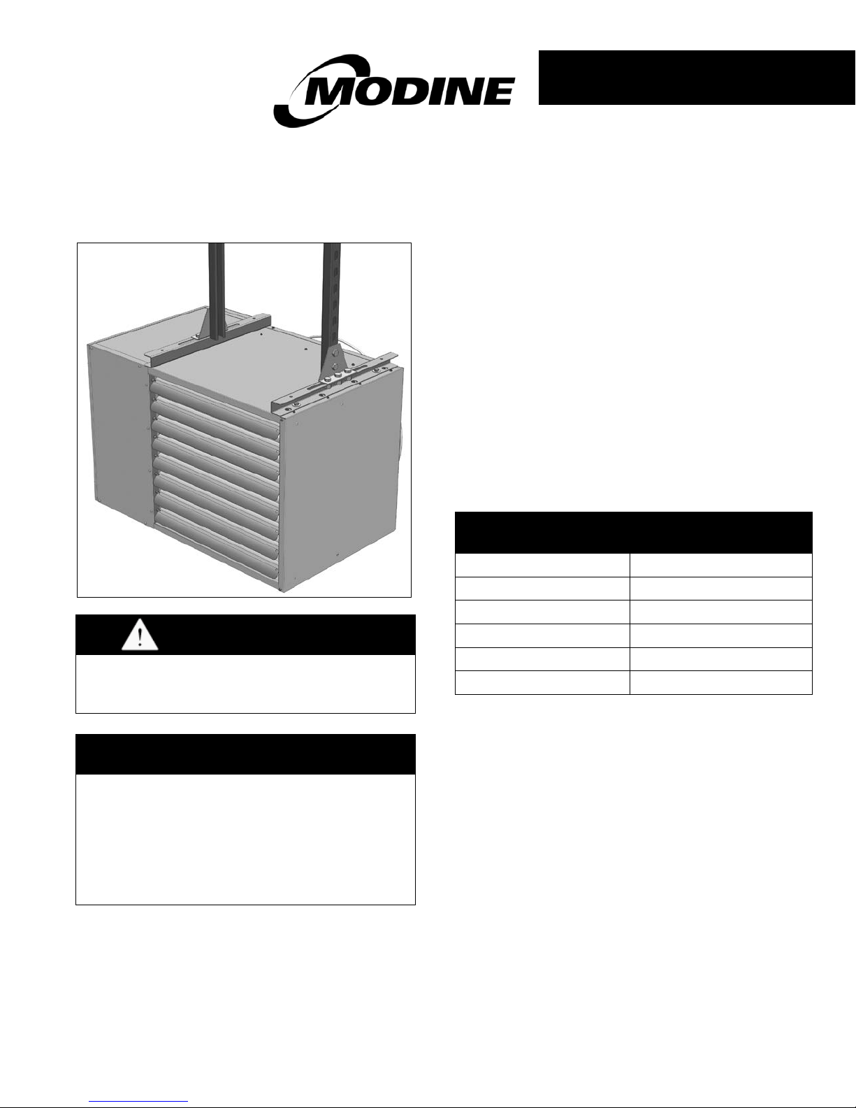
Two-Point Mounted Unit Heater
Sept, 2015
INSTALLATION INSTRUCTIONS
two-point mounting kit
models HD/HDS (100 & 125 only), PTC, PTS, PTP, PDP (350 &400)
2-POINT MOUNTING KIT
Model Application
On occasion, building structures may not easily accommodate
the standard four-point uni t suspen sio n on HD/HDS (100 &
125 only), PTC (85-310 only), PTS, PTP, PDP (350 &400)
models. For those cases, Modine offers a two-point mou nti ng
conversion kit, which can be used to convert the unit to twopoint suspension. The conversion kit includes two heavy
gauge "C" channel brackets and two angle brackets, along
with required fasteners to attach the brackets to the heater.
To ensure adequate suspension of the unit is achieved, follow
these instructions in detail. For complete unit installation
instructions, please refer to the latest revision of the
Installation & Service Manual that shipped with the unit.
These are summarized in Table 1.1.
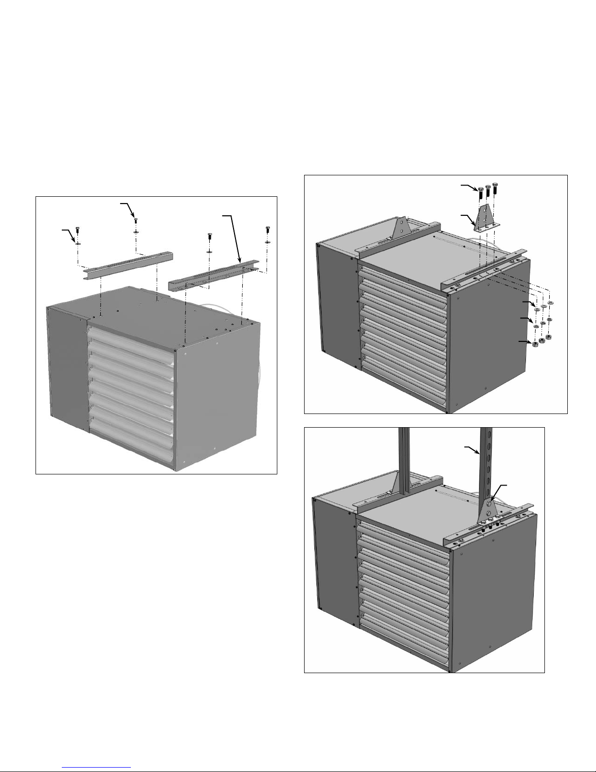
Figure 2.2 – Angle Bracket Installation
Model
Installation & Service
Manual
disconnected before proceeding with the conversion.
Failure to do so could result in fire, explosion, electrical
qualified installation and service agency. All installation
and service of these kits must be performed by a
qualified installation and service agency.
2. These instructions must also be used in conjunction
with the Installation and Service (I&S) Manual originally
shipped with the appliance being converted, in addition
to any other accompanying component supplier
HD 100 & 125 6-583
As shipped with the unit, or latest revision.
HDS 100 & 125 6-584
PTC (85–310) 6-563
PTS, 6-561
PDP 350 & 400 6-580
PTP 6-560
Detailed instructions for the assembly/installation of
the two-point mounting kit are on the reverse side of
this sheet.
PLEASE BE SURE TO LEAVE IT WITH THE OWNER WHEN YOU LEAVE THE JOB.
THIS MANUAL IS THE PROPERTY OF THE OWNER.
INSTALLATION – 2-POINT MOUNTING KIT ACCESSORY
3/8” FLAT
WASHER
3/8” – 16 x 1” HEX
HEAD MACHINE BOLT
“C” CHANNEL
BRACKET
1/2” LOCK
WASHER
1/2” – 16
NUT
1/2” – 16 x 1-1/2” HEX
HEAD MACHINE BOLT
ANGLE BRACKET
UNISTRUT P3000T
OR EQUIVALENT
(BY OTHERS)
FASTENERS
(BY OTHERS)
1/2” FLAT
WASHER
Assembly/Installation
The recommended procedure for assembly and installation is
described as follows (refer to Figures 2.1 and 2.3):
1. Attach both "C" Channel Brackets to the existing unit
suspension holes using the hardware supplied with the
mounting kit. Each bracket is attached using (2) 3/8"-16
x 1” hex head machine bolts and (2) 3/8” flat washers.
Refer to Figure 2.1.
Figure 2.1 – “C” Bracket Installation
the angle brackets are connected to the vertical supports
at the same height. Once the unit is level, tighten the
nuts from Step 2.
5. Continue with the gas, electric, and venting installation
instructions listed in the I&S Manual that shipped with the
unit. Be sure to follow all cautionary notes. Re-check
that the unit is level and that nothing has shifted once the
installation of the unit has been completed .
Figure 2.2 – Angle Bracket Installation
Figure 2.3 – Two-Point Mounted Unit Heater
2. Attach one of the angle brackets to the top of each “C”
channel. Each angle bracket is attached using (3) 1/2”16 x 1-1/2” hex head machine bolts, (3) 1/2” flat washers,
(3) 1/2” lock washers, and (3) 1/2”-16 nuts. Refer to
Figure 2.2. Hand tighten the nuts to allow unit balancing
in Step 4.
3. Ensure that the vertical supports (Unistrut P3000T or
equivalent, by others) from which the unit will be
suspended are plumb and rigidly supported. Raise the
unit to its mounting position and align the angle brackets
with the vertical supports as shown in Figure 2.3. Fasten
the angle brackets to the vertical supports (fasteners are
by others).
4. After securing the unit to the two vertical supports,
ensure that the unit is level both front to back and side to
side. The slotted mounting holes in the “C” channel
allow the unit to be moved forward or backwards until it is
level front to back. To level the unit side to side, ensure
Modine Manufacturing Company has a continuous product improvement program,
and therefore reserves the right to change design and specifications without notice.
Modine Manufacturing Company • 1500 DeKoven Avenue • Racine, Wisconsin, USA 53403-2552
Phone: 1.800.828.4328 (HEAT) • www.modinehvac.com
© Modine Manufacturing Com p an y 2015 6-574.2
 Loading...