

Modine Manufacturing HDB, HD, HDS, HDC, PDP Installation Instructions Manual
...
75-507.6
5H70392A
January, 2016
INSTALLATION INSTRUCTIONS
energy-saver controller for gas-fired unit heaters
models HD/HDB, HDS/HDC, PDP/BDP, PTC, PTP, PTS/BTS
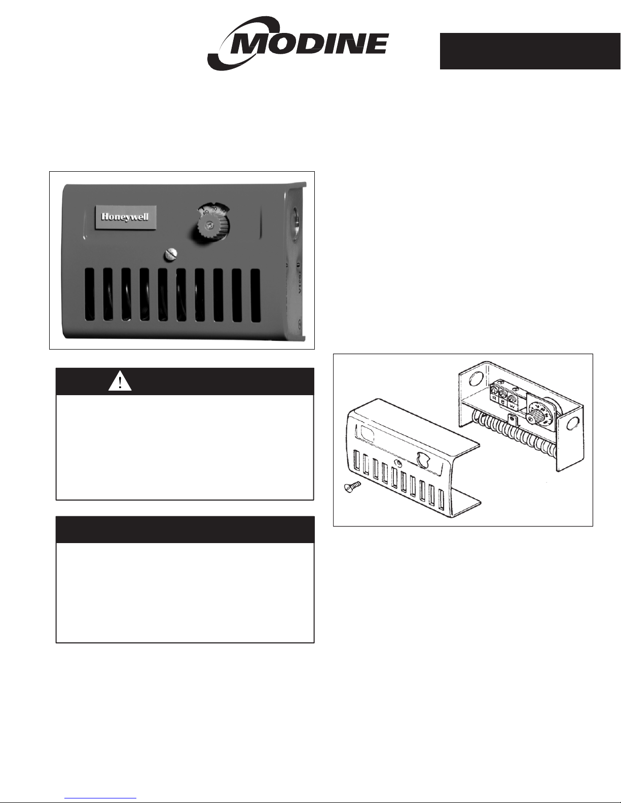
Figure 1.1 - Energy Saver Control
WARNING
1. Disconnect power supply before making wiring connections
to prevent electrical shock and equipment damage.
2. All units must be wired strictly in accordance with wiring
diagram furnished with the unit. Any wiring different from
the wiring diagram could result in a hazard to persons and
property.
3. All wiring must be done with a wiring material having a
temperature rating of at least 105°C.
IMPORTANT
1. The use of this manual is specifically intended for a
qualified installation and service agency. All installation
and service of these kits must be performed by a qualified
installation and service agency.
2. These instructions must also be used in conjunction with
the Installation and Service Manual that originally shipped
with the appliance, in addition to any other accompanying
component supplier literature.
Application
The energy-saver control utilizes stratified ceiling air to heat
the space at floor level before turning on the gas controls. Its
operation is independent of the room thermostat and should
have a higher set-point than the room thermostat. As
temperature increases at the ceiling, the control will energize
the unit heater fan only, to deliver hot air to the space below. If
the room thermostat determines additional heat is required, it
will energize the unit heater gas controls.
Installation
All wiring for this control must comply with the National
Electric Code and all local codes and ordinances.
1. Disconnect power to unit heater.
2. Remove front cover and one wiring access knockout from
control (see Figure 1.2).
3. Attach control to mounting surface adjacent to the unit
heater with three screws through back of case. Use a
wooden shim for insulation if surface is metal or masonry.
Do not locate control on an outside wall or where it will be
affected by drafts or radiant heat.
4. Wire the R and W terminals to the unit heater as shown in
Figures 2.1 through 2.3. Replace the energy saver control
cover.
Figure 1.2 - Energy Saver Control Internal Details
Operational Check
1. Set room thermostat to its lowest setting and restore power
supply to unit heater.
2. Turn the adjustment dial on the energy saver control
clockwise to a lower setting and only the unit heater fan
should come on. If the wiring is correct, the controlled
equipment will switch on and off as the temperature dial
indicates the approximate space temperature.
3. If the controlled equipment does not start and stop as the
thermostat dial is turned, disconnect the power supply and
check the wiring and terminal connections.
4. After checkout, reset room thermostat to desired comfort
level. Set energy-saver control 3 to 6 degrees above room
thermostat (depending on mounting height, room
conditions, etc.) for ceiling air circulation.

WIRING INSTRUCTIONS FOR ENERGY SAVER CONTROL
Figure 2.1 - Energy Saver Control Wiring for Models HD/HDB, HDS/HDC, PTP, and PTS/BTS
Figure 2.2 - Energy Saver Control wiring for Models PDP/BDP
Figure 2.3 - Energy Saver Control wiring for Model PTC
Commercial Products Group • Modine Manufacturing Company • 1500 DeKoven Avenue • Racine, Wisconsin 53403-2552
Phone: 1-800-828-4328 (HEAT)
© Modine Manufacturing Company 2016
 Loading...