

Modine Manufacturing BAE, PAE User Manual
!
R
APPROVED
R
C
E
R
T
I
F
I
E
D
D
E
S
I
G
N
GAS
A
S
S
O
C
I
A
T
I
O
N
A
S
S
O
C
I
A
T
I
O
N
A
M
E
R
I
C
A
N
A
M
E
R
I
C
A
N
6-551.31
art 5H70880A (Rev. AA)
P
July, 1996
NSTALLATION AND SERVICE MANUAL
I
gas-fired unit heaters
models PAE and BAE
All models approved for use in California by the CEC (when
equipped with IPI), in New York by the MEA division, and in
Massachusetts. Unit heater is certified for non-residential
applications.
WARNING
Im pr oper i ns tallation , adjust me nt, al te ration, service or
maintenance can cause property damage, injury or death, and
co uld cau se e xposu re t o su bst an ces whi ch h ave been
determined by various state agencies to cause cancer, birth
defects or other reproductive harm. Read the installation,
operating and maintenance instructions throroughly before
installing or servicing this equipment.
FOR YOUR SAFETY
The use and storage of gasoline or other flammable vapors
and liquids in open containers in the vicinity of this appliance is
hazardous.
Contents
Pages
Inspection on arrival . . . . . . . . . . . . . . . . . . . . . . . . . . . . . . . . .1
Installation (including venting) . . . . . . . . . . . . . . . . . . . . . . .2-8
Operation . . . . . . . . . . . . . . . . . . . . . . . . . . . . . . . . . . . . . .9-10
Checking input rate . . . . . . . . . . . . . . . . . . . . . . . . . . . . . . . .11
Dimensional data . . . . . . . . . . . . . . . . . . . . . . . . . . . . . .12 & 15
Performance data . . . . . . . . . . . . . . . . . . . . . . . .13, 14 & 16-19
Service instructions – safety devices . . . . . . . . . . . . . . . .20-21
Service instructions – general . . . . . . . . . . . . . . . . . . . . . . . .22
Troubleshooting . . . . . . . . . . . . . . . . . . . . . . . . . . . . . . . .21-24
Motor data . . . . . . . . . . . . . . . . . . . . . . . . . . . . . . . . . . . . .25-26
Control options . . . . . . . . . . . . . . . . . . . . . . . . . . . . . . . . . . . .27
Model identification . . . . . . . . . . . . . . . . . . . . . . . . . . . . . . . .28
Warranty . . . . . . . . . . . . . . . . . . . . . . . . . . . . . . . . . .Back cover
FOR YOUR SAFETY
If you smell gas:
1. Open windows
2. Don't touch electrical switches.
3. Extinguish any open flame.
4. Immediately call your gas supplier.
THIS MANUAL IS T HE PROPERTY O F THE OWNER.
PL EA SE BE SURE TO L EAVE I T WITH THE OW NE R
WHEN YOU LEAVE THE JOB.
To prevent premature heat exchanger failure
do not locate ANY gas-fired units in areas
wher e chlo rinated, halogenate d or acid
vapors are present in the atmosphere.
Inspection on Arrival
1. In sp ect un it upo n arr iv al. In case of damage, repor t
immediately to transportation company and your local
Modine sales representative.
2.
Check rating plate on unit to verify that power supply meets
available electric power at the point of installation.
3. Inspect unit received for conformance with description of
product ordered (including specifications where applicable).
Heater Parts from ACF Greenhouses
INSTALLATION
SPECIAL PRECAUTIONS
THE INSTALLATION AND MAINTENANCE INSTRUCTIONS IN THIS
MANUAL MUST BE FOLLOWED TO PROVIDE SAFE, EFFICIENT
AND TROUBLE-FREE OPERATION. IN ADDITION, PARTICULAR
CARE MUST BE EXERCISED REGARDING THE SPECIAL
PRECAUTIONS LISTED BELOW. FAILURE TO PROPERLY
ADDRESS THESE CRITICAL AREAS COULD RESULT IN
PROPERTY DAMAGE OR LOSS, PERSONAL INJURY, OR DEATH.
1. Disconnect power supply before making wiring connections to
prevent electrical shock and equipment damage. All units must be
wired strictly in accordance with wiring diagram furnished with the
unit.
2. Turn off all gas before installing unit heaters.
3. Gas pressure to unit heater controls must never exceed 14” W.C.
(1/2 psi).
When leak testing the gas supply piping system, the unit and its
combination gas control must be isolated during any pressure
testing in excess of 14’ W.C. (1/2 psi).
The unit should be isolated from the gas supply piping system by
closing its field installed manual shut-off valve.
4. Check gas inlet pressure at unit upstream from the combination gas
control. The inlet pressure should be 6”-7” W.C. on natural gas or
12”-14” W.C. on propane gas. Purging of gas piping should be
performed as described in ANSI Z223.1 Latest Edition, or in
Canada in CAN/CGA-B149 codes.
5. All units must be vented to the outside atmosphere.
6. Do not install in potentially explosive or flammable atmospheres
laden with grain dust, sawdust, or similar air-borne materials. In
such applications a blower type heater installed in a separate room
with ducting, including appropriate back flow prevention dampers,
to the dust-laden room is recommended.
7. Installation of units in high humidity or salt water atmospheres will
cause accelerated corrosion resulting in a reduction of the normal
life span of the units.
8. To prevent premature heat exchanger failure do not locate ANY
gas-fired unit in areas where chlorinated, halogenated or acid
vapors are present in the atmosphere.
9. Avoid installing units in extremely drafty locations. Drafts can cause
burner flames to impinge on heat exchangers which shortens life.
Maintain separation between units so discharge from one unit will
not be directed into the inlet of another.
10. Do not locate units in tightly sealed rooms or small compartments
without provision for adequate combustion air and venting.
Combustion air must have access to the confined space through a
minimum of two permanent openings in the enclosure, at least one
near the bottom. They should provide a free area of one square
inch per 1000 BTU per hour input rating of the unit with a minimum
of 100 square inches for each opening, whichever is greater.
11. Do not install unit outdoors.
12. For all sizes, minimum clearance to combustibles from the bottom
is 12 inches and from the sides 18 inches; for sizes 30-100 from the
top is 1 inch and from the vent connector 2 inches; for sizes 125300 from the top is 2 inches and from the vent connector 3 inches;
and for sizes 350 & 400 from the top is 3 inches and from the vent
connector 6 inches.
13. Allow at least 6” clearance at the sides and 12” clearance at rear (or
6” beyond end of motor at rear of unit, whichever is greater) to
provide ample air for combustion and proper operation of fan.
14. The minimum distance from combustible materials based on the
combustible material surface not exceeding 160°F. Clearance from
the top of the unit may be required to be greater than 6” if heat
damage, other than fire, may occur to materials above the unit
heater at the temperature described.
15. Do not install units below 7 feet measured from the bottom of the
unit to the floor.
16. Modine unit heaters are designed for use in heating applications
with ambient temperatures between 32° F and 90° F If an
application exists where ambient temperatures can be expected to
fall outside of this range, contact factory for recommendations.
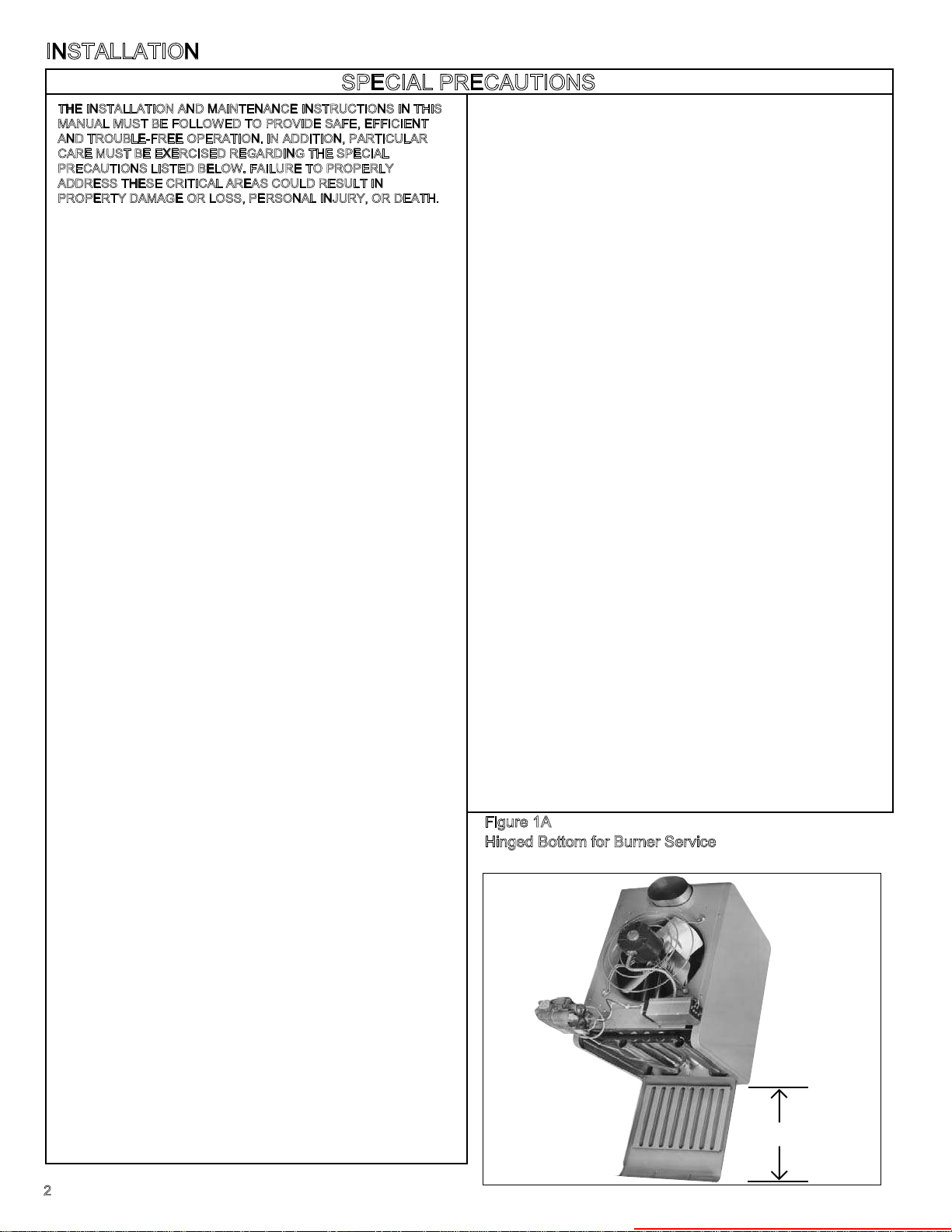
17. Provide clearance for opening hinged bottom for servicing. See
Figure 1A. Do not set unit on its bottom.
18. To assure that flames do not impinge on heat exchanger surfaces,
the unit must be suspended in a vertical and level position. Failure
to suspend unit properly may shorten the life of the unit heater.
19. Do not lift unit heater by gas controls, gas manifold, or power venter.
20.
Be sure no obstructions block air intake and discharge of unit heater.
21. Do not attach duct work, air filters, or polytubes to any propeller
(PAE) model unit heaters.
22. In aircraft hangars, keep the bottom of the unit at least 10’ from the
highest surface of the wings or engine enclosure of the highest
aircraft housed in the hangar and in accordance with the
requirements of the enforcing authority and/or NFPA No. 409 –
Latest Edition .
23. In garages or other sections of aircraft hangars such as offices and
shops which communicate with areas used for servicing or storage,
keep the bottom of the unit at least 7’ above the floor. In public
garages, the unit must be installed in accordance with the Standard
for Parking Structures NFPA #88A and the Standard for Repair
Garages NFPA #88B. In Canada, installation of unit heaters in
airplane hangars must be in accordance with the requirements of
the enforcing authority, and in public garages in accordance with
the current CAN/CGA-B149 codes.
24. Consult piping, electrical, and venting instructions in this manual
before final installation.
25. All literature shipped with your unit should be kept for future use for
servicing or service diagnosis. Do not discard any literature shipped
with your unit.
26. Gas-fired heating equipment which has been improperly vented, or
which experiences a blocked vent condition may have the flue
gases accidentally spilled into the heating space. See page 20 for
specific information about the blocked vent safety switch supplied
on the unit.
27.
When servicing or repairing this equipment, use only Modine
approved service replacement parts. A complete replacement parts
list may be obtained by contacting Modine Manufacturing Company.
Refer to the rating plate on the unit for complete unit model number,
serial number and company address. Any substitution of parts or
controls not approved by Modine will be at owners risk.
Figure 1A
Hinged Bottom for Burner Service
*(See Dimension "C" Table 6, page 12)
*MIN.
2
Heater Parts from ACF Greenhouses
INSTALLATION
!
!
In the U.S., the installation of these units must comply with the “National
Fuel Gas Code,” ANSI Z223.1, latest edition (also known as NFPA 54)
and other applicable local building codes.
In Canada, the installation of these units must comply with local
plumbing or waste water codes and other applicable codes and with the
current code CAN/CGA-B149.1, “Installation Code for Natural Gas
Burning Appliances and Equipment” or CAN/CGA-B149.2, “Installation
Code for Propane Burning Appliances and Equipment.”
1. Alliinstallation and service of these units must be performed by a
qualified installation and service agency only as defined in ANSI
Z223.1, latest edition or in Canada by a licensed gas fitter.
2. This unit is certified by A.G.A. and by C.G.A., with the controls
furnished. For replacement parts, submit the complete model and
serial numbers shown on rating plate on the unit. Modine reserves
the right to substitute other authorized controls as replacements.
3. Unit is balanced for correct performance. Do not alter fan or operate
motors at reduced speed.
4. Information on controls is supplied separately.
5. Modine unit heaters use the same burner for natural and propane
gases.
Locating Unit Heaters
CAUTION
Units must not be installed in potentially explosive, flammable
or corrosive atmosphere.
To prevent premature heat exchanger failure do not locate
ANY gas-fired unit in areas where chlorinated, halogenated
or acid vapors are present in the atmosphere.
In locating units, consider general space-heating requirements,
availability of gas, and proximity to vent locations. Unit heaters should
be located so heated air streams wipe exposed walls without blowing
directly against them. In multiple unit installations, arrange units so that
each supports the air stream from another, setting up circulatory air
movement in the area, but maintain separation between units so
discharge from one unit will not be directed into the inlet of another. In
buildings exposed to prevailing winds, a large portion of the heated air
should be directed along the windward wall. Avoid interference of air
streams as much as possible.
Mounting height (measured from bottom of unit) at which unit heaters
are installed is critical. Maximum mounting heights are listed in Table 7
on page 18. Alternate mounting heights for units with deflector hoods or
nozzles are shown on pages 14,16 and 17. The maximum mounting
height for any unit is that height above which the unit will not deliver
heated air to the floor.The maximum mounting heights must not be
exceeded in order to assure maximum comfort.
Modine unit heaters are designed for use in heating applications with
ambient temperatures between 32° F and 90° F. If an application exists
where ambient temperatures can be expected to fall outside of this
range, contact factory for recommendations.
Combustion Air Requirements
Units installed in tightly sealed buildings or confined spaces should be
provided with two permanent openings, one near the top of the
enclosure and one near the bottom. Each opening should have a free
area of not less than one square inch per 1,000 BTU per hour of the
total input rating of all units in the enclosure, freely communicating with
interior areas having, in turn, adequate infiltration from the outside.
Unit Suspension
Be sure the means of suspension is adequate to support the weight of the
unit. (See page 12 for unit weights.) For proper operation, the unit must be
installed in a level horizontal position. Clearances to combustibles as
specified above must be strictly maintained. Do not install standard unit
heaters above the maximum mounting height shown in Table 7 on page
13, or below seven feet from the bottom of the unit to the floor.
CAUTION
For all sizes, minimum clearance to combustibles from the
bottom is 12" and from the sides 18"; for PAE sizes 30-100
from the top is 1" and from the vent connector 2"; for PAE
sizes 125-300 from the top is 2" and from the vent connector
3"; for PAE sizes 350 & 400 from the top is 3" and from the
vent connector 6”; and for all BAE sizes from the top and vent
connector is 6".
Allow at least 12" at the rear, or 6" beyond the end of the
motor (whichever is greater), to provide ample air for
combustion and for proper operation of fan. Provide
clearance for opening of the hinged bottom for servicing –
SEE FIGURE 1A.
On all propeller units, except the PAE 300, PAE 350 and PAE 400, two
tapped holes (3/8-16) are located in the top of the unit to receive ceiling
hangers.
Units with two point suspension, models PAE30 through PAE250,
incorporate a level hanging feature. Depending on what options and
accessories are being used, the heater may not hang level as received
from the factory. Do not hang heaters with deflector hoods until referring
to the “installation manual for deflector hoods” and making the
recommended preliminary adjustments on the heater. These preliminary
adjustments need to be made with the heater resting on the floor.
PAE30 through PAE250 units without deflector hoods that do not hang
level after being installed, can be corrected in place. Simply remove
both outer side panels (screws to remove are on back flange of side
panel) and you will see the (adjustable) mounting brackets (Fig. 2).
Loosen the set screws holding the mounting brackets in place and using
a rubber mallet or something similar, tap the heater into a position
where it does hang level. Re-tighten set screws and replace the outer
side panels
The PAE 300, PAE 350 and PAE 400 have four mounting holes. On all
blower units, except the PAE 300, PAE 350 and PAE 400, two tapped
holes are provided in the top of the unit and two holes in the blower
support bracket. The PAE 300, PAE 350 and PAE 400 have four tapped
holes in the top of the unit and two in the blower support bracket for
mounting.
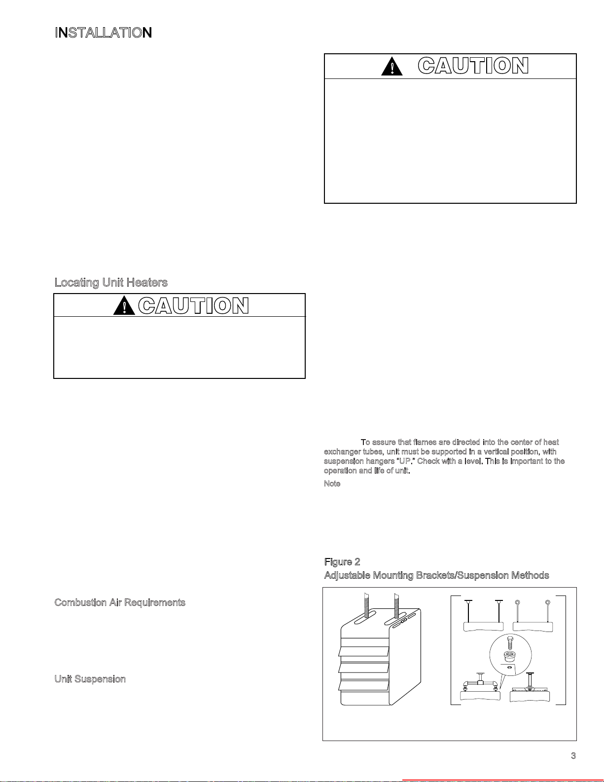
exchanger tubes, unit must be supported in a vertical position, with
suspension hangers “UP.” Check with a level. This is important to the
operation and life of unit.
Note
accessories from Modine. The hardware allows for pipe caps to be
secured into the top of the unit heater with machine screws (as
illustrated - machine screws are 3/8 - 16 x 1.75 UNC-2A THD). The pipe
caps can then accommodate 3/4" NPT pipe for mounting. Three
different kits are available with either 2, 4, or 6 adapters per kit. See
price sheet to determine proper kit.
Figure 2
Adjustable Mounting Brackets/Suspension Methods
REMOVE SIDE PANELS TO
o assure that flames are directed into the center of heat
T
: Pipe hanger adapter kits, as shown in Figure 2, are available as
ADJUST MOUNTING
BRACKETS
SUSPENSION WITH PIPE
ADAPTER KIT
3
Heater Parts from ACF Greenhouses
INSTALLATION
!
CAUTION
Gas Unit H eat ers m ust b e ven ted – d o not o per ate
unvented.
A built-in draft hood (diverter) is provided – additional
ext ern al draf t hoo ds (d iver ter s) are not requ ire d or
permitted.
Gas-fired heating equipment that has been improperly
vented or which experiences a blocked vent condition may
have flue gases accidentally spilled into the heated space.
See page 20 for specific information about the blocked vent
safety switch supplied on the unit.
Installation must conform with local building codes or in the
absence of local codes, with Part 7, Venting of Equipment,
of the National Fuel Gas Code, ANSI Z223.1 (NFPA 54) Latest Edition. In Canada installation must be in accordance
with CAN/CGA-B149.1 for natural gas units, and CAN/CGAB149.2 for propane units.
NOTE:
V
1. Using Table 1, determine the venting system category of the unit to be
2. Using Table 2, determine the venting requirements for the category
3.
4. Limit length of horizontal runs to 75% of vertical height. Install with a
5. Avoid venting through unheated space when possible. When venting
6. Keep single wall vent pipe at least 6 inches from combustible material
7. Where the vent passes through a combustible floor or roof, a metal
8.
9. Use a vent terminal to reduce downdrafts and moisture in vent. A vent
ent
v
A
unit or the vent connector to the outside atmosphere. A
is the vertical passageway used to convey flue gases from the
the pipe which connects the unit to a vent or chimney.
ent connector
v
enting Instructions
installed.
determined above. The installation of a Category II unit must conform to
these requirements (detailed in following sections) in addition to those
listed below.
Select size of vent pipe to fit vent pipe connection at rear of appliance (see
Page 12, Dimension J). (Exception: All PAE/BAE 50 models with two-stage
or modulating controls must use a 5 inch vent.) Do not use a vent pipe
smaller than the vent pipe connection on the unit. Vent pipe should be
galvanized steel or other suitable corrosion-resistant material. Follow the
National Fuel Gas Code for minimum thicknesses of vent material; minimum
thicknesses for vent connectors vary depending on pipe diameter.
minimum upward slope from unit of 1/4 inch per foot and suspend
securely from overhead structure at points no greater than 3 feet apart.
For best venting, put as much vertical vent as close to the unit as
possible. Fasten individual lengths of vent together with at least three
corrosion-resistant sheet-metal screws.
does pass through an unheated space, Modine recommends the use of
Type B double wall vent. If single wall vent is used, insulate vent runs
greater than 5 feet to minimize condensation. Use insulation that is
noncombustible with a rating of not less than 350°F. Install a tee fitting at
the low point of the vent system to provide a drip leg with a clean out cap
as shown in Figure 3. The drip leg should be cleaned annually.
(see page 2, section 12 for allowable reductions). For double wall vent
pipe, maintain clearances listed on vent pipe (Category I and II units).
The minimum distance from combustible material is based on the
combustible material surface not exceeding 160°F. Clearance from the
vent connector, vent, or top of unit may be required to be greater than
the minimum clearance if heat damage other than fire (such as material
distortion or discoloration) may occur.
thimble 4 inches greater than the vent diameter is necessary. If there is 6
feet or more of vent pipe in the open space between the unit and where
the vent pipe passes through the floor or roof, the thimble need only be 2
inches greater than the diameter of the vent pipe. If a thimble is not
used, all combustible material must be cut away to provide the specified
clearance to combustibles. Any material used to close the opening must
be noncombustible.
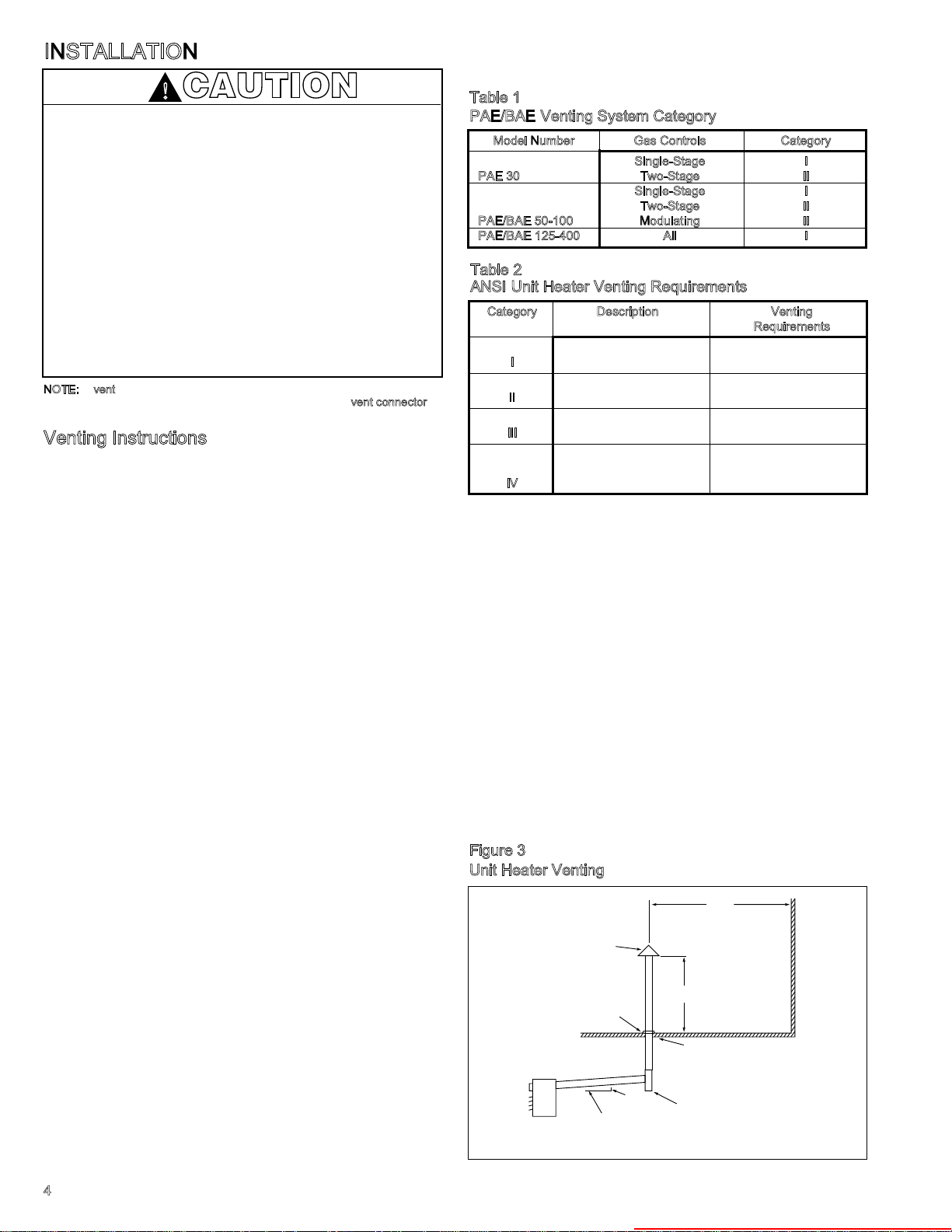
Top of vertical vent should extend at least two feet above the highest
point where it passes through a roof and at least 2 feet higher than any
portion of a building within a horizontal distance of 10 feet (see Figure 3).
terminal that is very open will avoid spillage at unit’s diverter relief
opening and tripping of the blocked vent safety switch.
Table 1
PAE/BAE Venting System Category
Model Number Gas Controls Category
Single-Stage I
PAE 30 Two-Stage II
Single-Stage I
Two-Stage II
PAE/BAE 50-100 Modulating II
PAE/BAE 125-400 All I
Table 2
ANSI Unit Heater Venting Requirements
Category Description Venting
Negative vent pressure Follow standard
I
Non-condensing venting requirements.
Negative vent pressure Condensate must be
is
II
Condensing drained.
Positive vent pressure Vent must be gastight.
III
Non-condensing
Positive vent pressure Vent must be liquid and
Condensing gastight. Condensate
IV
Check vent system to see that combustion products are being vented
10.
properly. Operate unit for several minutes and then pass a lighted match
around the edge of the diverter relief opening. If the flame is drawn into
the opening, the vent system is drawing properly. If not, make
adjustments to provide adequate draft (see page 21).
ADDITIONAL VENTING REQUIREMENTS FOR CATEGORY II UNITS
Vent system must provide for drainage of condensate. At the low point of the
vent system, install a tee fitting with a connector and attach flexible tubing,
minimum 3/8 inch I.D., and run to a drain.
ADDITIONAL VENTING REQUIREMENTS FOR VENTING INTO AN
EXISTING MASONRY CHIMNEY OR COMMON VENT (CATEGORY I and II
UNITS ONLY)
1. Do not vent a Category I or II unit into a common vent with mechanical
draft systems operating under positive pressure (Category III or IV units).
2. When connecting vent to an existing chimney, do not push vent pipe
beyond internal surface of chimney.
3. When venting into a common vent, the area of the common vent should
be equal to or greater than the area of the largest vent plus 50 percent of
the area of all additional vents.
4. When venting into a common vent, the individual vents should enter at
different levels
Requirements
must be drained.
Figure 3
Unit Heater Venting
10' MIN.
TO WALL OR ADJOINING BUILDING
APPROVED
TERMINAL
2'
*
MIN.
ROOF FLASHING
USE THIMBLE
THROUGH CEILING
1/4"
UNIT
1'0"
SLOPE 1/4" TO
THE FOOT
*SIZE ACCORDING TO EXPECTED SNOW DEPTH.
DRIP LEG WITH
CLEANOUT CAP
4
Heater Parts from ACF Greenhouses
GAS
SUPPLY LINE
GAS
SUPPLY LINE
GROUND
JOINT
UNION
MANUAL
SHUT-OFF
VALVE
3"
MIN.
SEDIMENT
TRAP
PLUGGED
1/8" NPT TEST
GAGE CONNECTION
TO
CONTROLS
!
INSTALLATION
Piping
CAUTION
Gas pressure to unit heater controls must never exceed 14"
W.C. (1/2 psi).
When leak testing the gas supply piping system, the
appliance and its combination gas control must be isolated
during any pressure testing in excess of 14" W.C. (1/2 psi).
The appliance should be isolated from the gas supply piping
system by closing its field installed manual shut-off valve.
1. Installation of piping must be in accordance with local
codes, and ANSI Z223.1, “National Fuel Gas Code,” or
CAN/CGA-B149 in Canada.
2. Piping to units should conform with local and national
requirements for type and volume and gas handled, and
pressure drop allowed in the line. Refer to Table 4, to
determine the cubic feet per hour (cfh) for the type of gas
and size of unit to be installed. Using this cfh value and the
length of pipe necessary, determine the pipe diameter from
Table 1. Where several units are served by the same main,
the total capacity, cfh, and length of main must be
considered. Avoid pipe sizes smaller than 1/2”. Table 1
allows for the usual number of fittings with a 0.3” W.C.
pressure drop. Where the gas supplied has a specific
gravity other than 0.60, apply the multiplying factor as given
in Table 2.
3. After threading and reaming the ends, inspect piping and
remove loose dirt and chips.
D
o not use flexible connectors
4. Support piping so that no strains are imposed on unit or
controls.
5. Use two wrenches when connecting piping to unit controls.
6. Provide a sediment trap before each unit and in the line
where low spots cannot be avoided. (See Figure 4).
7. Take-off to unit should come from top or side of main to
avoid trapping condensate.
8.
Piping, subject to wide temperature variations, should be
insulated.
9. Pitch piping up toward unit at least 1/4” per 15’ of horizontal
run.
10. Compounds used on threaded joints of gas piping must be
resistant to action of liquefied petroleum gases.
11. Purge air before lighting unit by disconnecting pilot tubing at
.
combination gas control.
I
n no case should line be purged
into heat exchanger.
12. After installation, check system for gas leaks, using a soap
solution.
13. Install a ground joint union and a manual shut off valve
immediately upstream of the unit including a 1/8” NPT
plugged tapping accessible for test gage connection. (See
Figure 4).
14. Allow at least 5 feet of piping between any high pressure
regulator and unit control string.
15. When leak testing the gas supply piping system, the
appliance and its combination gas control must be isolated
during any pressure testing in excess of 14” W.C. (1/2 psi)
The appliance should be isolated from the gas supply
piping system by closing its field installed manual shutoff
valve.
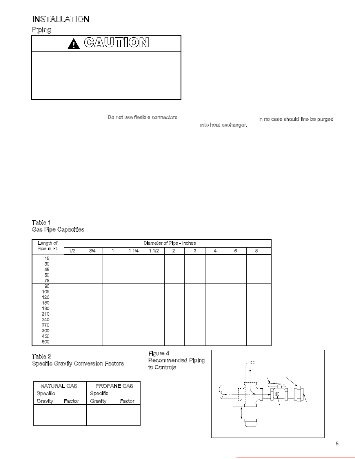
Table 1
Gas Pipe Capacities
In Cu. Ft. per Hour with Pressure Drop pf 0.3 in. W.C. with Specific Gravity 0.60.
Length of
Pipe in Ft.
15
3
0
45
60
75
0
9
1
05
120
150
180
210
2
40
270
00
3
50
4
6
00
1/2 3/4 1 1 1/4 1 1/2 2 3 4 6 8
76 218 440 750 1220 2480 6500 13880 38700 79000
73 152 285 590 890 1650 4700 9700 27370 55850
44 124 260 435 700 1475 3900 7900 23350 45600
50 105 190 400 610 1150 3250 6800 19330 39500
97 200 345 545 1120 3000 6000 17310 35300
88 160 320 490 930 2600 5400 15800 32250
80 168 285 450 920 2450 5100 14620 29850
158 270 420 860 2300 4800 13680 27920
120 242 380 710 2000 4100 12240 25000
128 225 350 720 1950 4000 11160 22800
Table 2
Specific Gravity Conversion Factors
Multiplying factors to be sued with table 1 when the specific
gravity of gas is other than 0.60.
NATURAL GAS
Specific
Gravity Factor
0.55 1.04
0.60 1.00
0.65 0.962
ROPANE GAS
P
Specific
Gravity Factor
1.50 0.633
1.53 0.626
1.60 0.612
Diameter of Pipe - Inches
205 320 660 1780 3700 10330 21100
190 300 620 1680 3490 9600 19740
178 285 580 1580 3250 9000 18610
170 270 545 1490 3000 8500 17660
140 226 450 1230 2500 7000 14420
119 192 380 1030 2130 6000 12480
Figure 4
Recommended Piping
to Controls
5
Heater Parts from ACF Greenhouses
12"
MIN.
A
B
BAFFLE
TURNING
VANES
12" MIN.
B
3" MAX.
TURNING
VANES
3" MIN.
A
A
3" MIN.
12"
MIN.
3" MAX.
TURNING
VANES
12"
B
BAFFLE
NSTALLATION
!
!
!
!
I
Wiring
CAUTION
Disconnect power supply before making wiring connections
to prevent electrical shock and equipment damage. ALL
UNITS MUST BE WIRED STRICTLY IN ACCORDANCE
WITH WIRING DIAGRAM FURNISHED WITH UNIT.
ANY WIRING DIFFERENT FROM WIRING DIAGRAM MAY
BE HAZARDOUS TO PERSONS AND PROPERTY.
Any damage to or failure of Modine units caused by incorrect
wiring of the units is not covered by MODINE’S STANDARD
WARRANTY (see Back Cover).
All field installed wiring must be done in accordance with the
National Electrical Code ANSI/NFPA 70 – Latest Edition or
Canadian Electrical Code CSA C22.1 Part 1 or local codes. Unit
must be electrically grounded according to these codes. See
wiring diagram shipped with unit. For optional wiring diagrams
see Bulletin 6-443.
The power to these unit heaters should be protected with a
circuit breaker. Units for use with single-phase electric power,
should be provided with a manual motor starter, having properly
sized overload protection. Units for use with three-phase
electric power must be provided with a motor starter having
properly sized overload protection.
Location of thermostat should be determined by heating
requirements and be mounted on an inside wall about 5' above
floor level where it will not be affected by heat from the unit or
other sources, or drafts from frequently opened doors. See
instructions packed with thermostat.
I
nstallation of Blower Models (BAE UNITS)
CAUTION
Proper air flow and distribution, across the heat exchanger
must be provided to prevent early failure of the blower unit
heater.
Attachment of Field Installed Ductwork, Blower
dels (BAE) Models Only
CAUTION
Do not attempt to attach ductwork of any kind to propeller
PAE models.
Burned-out heat exchanger as well as shorter equipment life will
result from not providing uniform air distribution.
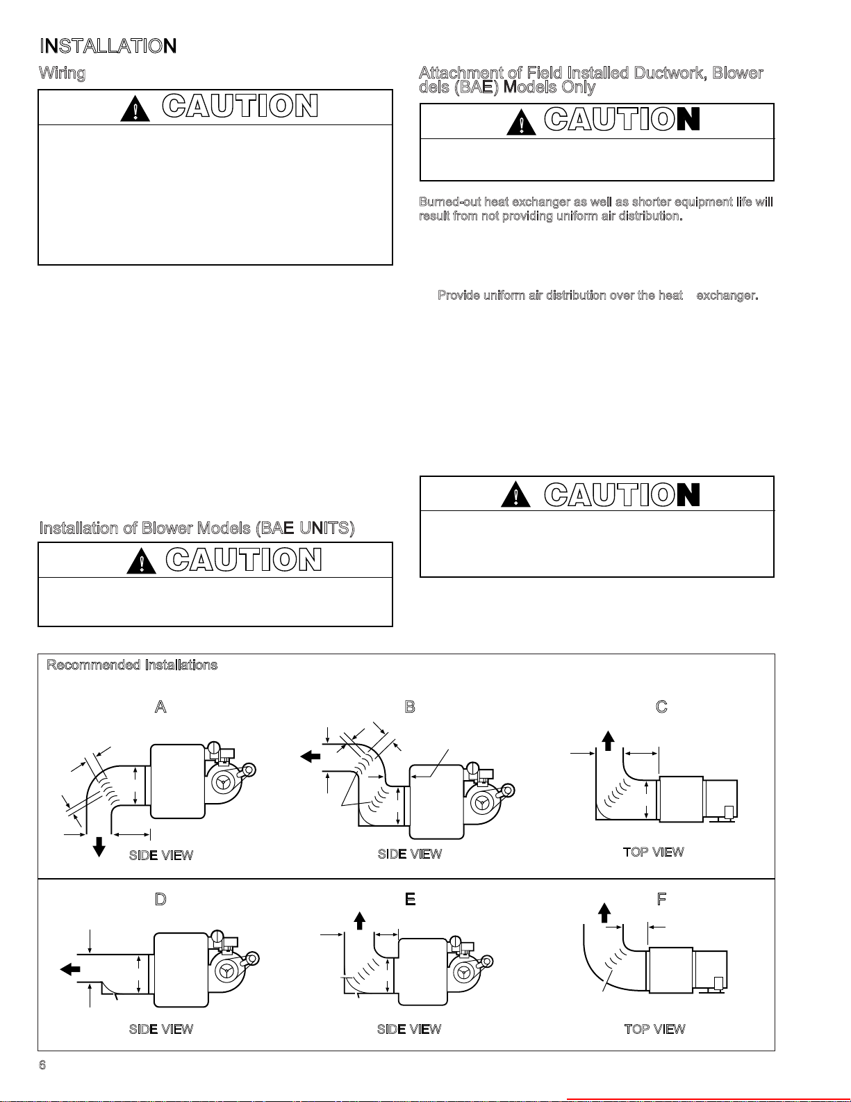
When installing heater always follow good duct design practices
for even distribution of the air across the heat exchanger.
Recommended layouts are shown below. When installing
blower units with ductwork the following must be done.
P
rovide uniform air distribution over the heat exchanger.
1.
Use turning vanes where required. See figures below.
2. Provide removable access panels in the ductwork on the
downstream side of the unit heater. These openings should
be large enough to view smoke or reflect light inside the
casing to indicate leaks in the heat exchanger and to check
for hot spots on exchanger due to poor air distribution or
lack of sufficient air.
3.
If ductwork is connected to the rear of the unit use Modine
blower enclosure kit or if using field designed enclosure maintain
dimensions of blower enclosure as shown on page 12.
CAUTION
Check for red heat exchanger tubes. If bottom of tubes
become red while blower unit is in operation, check for
proper air volume and air distribution. Adjust blower speed or
correct discharge duct design to correct problem.
Recommended Installations
SIDE VIEW
B
6
BAFFLE
SIDE VIEW SIDE VIEW TOP VIEW
Dimension “B” Should Never
Be Less than 1/2 of “A”
BA
B
SIDE VIEW
C
12"
MIN.
A
TOP VIEW
FED
12"
MIN.
A
TURNING
VANES
Heater Parts from ACF Greenhouses
INSTALLATION
Installation of Blower Models (BAE UNITS)
Determining Blower Speed
The drive assembly and motor on all gas-fired blower unit
heaters are factory assembled. The adjustable motor sheave
has been pre-set to permit operation of this unit under average
conditions of air flow and without any external static pressure.
The motor sheave should be adjusted as required when the unit
is to be operated at other than average air flows and/or with
external static pressures. Adjustment must always be within the
performance range shown on pages 18 and 19 and the
temperature rise range shown on the unit’s rating plate.
To determine the proper blower speed and motor sheave turns
open, the conditions under which the unit is to operate must be
known. If the blower unit is to be used without duct work,
nozzles or filters, the only criteria for determining the motor
sheave turns open and blower speed is the amount of air to be
delivered. The performance tables for blower models are shown
on pages 18 and 19. As an example, a model BAE 350 unit,
operating with no external static pressure, that is, no duct work,
nozzles, etc., and is to deliver an air volume of 6481 cfm (cfm =
cubic feet of air per minute) requires that the unit be supplied
with a 5 hp motor, a C116 drive, and the drive sheave must be
set at 3 turns open to achieve a blower speed of 940 rpm (see
performance table for units with or without blower enclosure,
page 18). See "Blower Adjustments" on page 8 for setting of
drive pulley turns open.
If a blower unit is to be used with ductwork or nozzles, etc., the
total external static pressure under which the unit is to operate,
and the required air flow must be known before the unit can be
properly adjusted. Any device added externally to the unit, and
which the air must pass through, causes a resistance to air flow.
This resistance is called pressure loss. The total of the pressure
losses must be determined before adjusting the blower speed.
If Modine filters are used, the expected pressure loss through
the filters is included in the performance data on page 19. If
Modine supplied discharge nozzles are used, the expected
pressure drop of the nozzles can be found footnoted at the
bottom of page 14. If filters, nozzles or ductwork are to be used
with the unit, and they are not supplied by Modine, the design
engineer or installing contractor must determine the pressure
loss for the externally added devices or ductwork to arrive at the
total external static pressure under which the unit is to operate.
Once the total static pressure and the required air flow are
known, the operating speed of the blower can be determined
and the correct motor sheave adjustments made. As an
example, let's say, a model BAE 350 is to be used with a
Modine supplied blower enclosure and Modine supplied filters
attached to someone else's ductwork. The unit is to move 6481
cfm or air flow against an external static pressure of 0.2" W.C.
Entering the performance table on page 19 (Blower models with
filters) for a BAE 350, at 6481 cfm and 0.2" W.C. static
pressure, it is seen that the unit will require a 5 hp motor using a
C116 drive, and the motor sheave should be set at .5 turns
open to achieve a blower speed of 1055 rpm. You can see this
example differs from similar conditions in paragraph 2 by the
number of turns open and a higher rpm, which is needed to
overcome the added external static pressure from the filters.
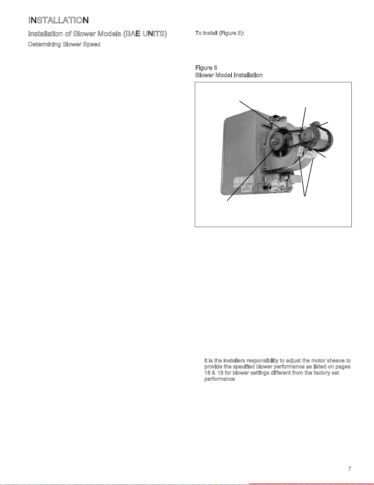
T
o Install (Figure 5):
1. Remove and discard the motor tie down strap and the
shipping block beneath the belt tension adjusting screw (Not
used on all models.)
Figure 5
Blower Model Installation
MOTOR MOUNTING
BRACKET
BLOWER
SHEAVE
2. Adjust motor adjusting screw for a belt deflection of
approximately 3/4" with five pounds of force applied midway
between the sheaves (refer to Figure 6a). Since the belt
tension will decrease dramatically after an initial run-in
period, it is necessary to periodically re-check the tension.
Excessive tension will cause bearing wear and noise.
3. The blower bearings are lubricated for life; however, before
initial unit operation the blower shaft should be lubricated at
the bearings with SAE 20 oil. This will reduce initial friction
and start the plastic lubricant flowing.
4. Make electrical connections according to the wiring
diagram.
5. Check rotation of the blower. Motor should be in clockwise
rotation when facing motor pulley. If rotation is incorrect,
correction should be made by interchanging wiring within
the motor. See wiring diagram on the motor.
6. The actual current draw of the motor should be determined.
Under no condition should the current draw exceed that
shown on the motor rating plate.
I
t is the installers responsibility to adjust the motor sheave to
7.
provide the specified blower performance as listed on pages
18 & 19 for blower settings different from the factory set
performance
. The drive number on the unit may be
identified by referring to the Power Code number on the
serial plate of the unit (see page 28 for model number
nomenclature) and matching that number with those shown
on page 25. From the listing, the drive number can be
determined.
8. Blower sheave and motor sheave should be measured to
assure correct drive is on unit. Refer to page 26 for drive
sizes.
MOTOR SHEAVE
(MOVEABLE FACE TO OUTSIDE)
OIL CUPS
UP
MOTOR
ADJUSTMENT
SCREW
TIE DOWN STRAP
& BLOCK FOR
SHIPPING ONLY
7
Heater Parts from ACF Greenhouses
INSTALLATION
Blower Adjustments
Following electrical connections, check blower rotation to assure
blow-through heating. If necessary interchange wiring to reverse
blower rotation. Start fan motor and check blower sheave RPM
with a hand-held or strobe-type tachometer. RPM should check
out with the speeds listed in Performance Data shown on pages
18 and 19. A single-speed motor with an adjustable motor
sheave is supplied with these units. If blower fan speed changes
are required, adjust motor sheave as follows:
NOTE: Do not fire unit until blower adjustment has been made
or unit may cycle on limit (overheat) control.
Shut-off power before making blower speed adjustments.
1.
Refer to Determining Blower Speed on page 7 and to Blower
Drive Selection on pages 18 and 19 to determine proper
blower RPM.
2. Loosen belt and take belt off of motor sheave.
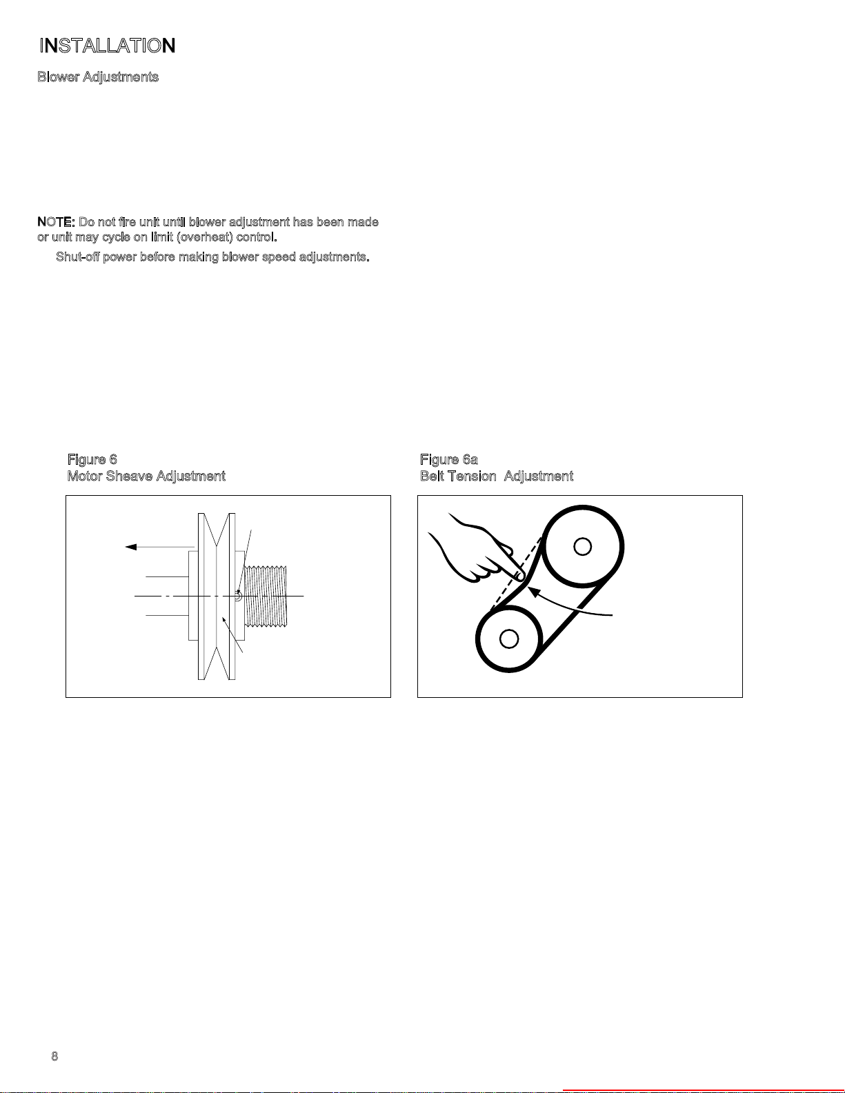
3. Loosen set screw on outer side of adjustable motor sheave
(see Figure 6).
4. To reduce the speed of the blower, turn outer side of motor
sheave counterclockwise.
Figure 6
Motor Sheave Adjustment
5. To increase the speed of the blower, turn outer side of motor
sheave clockwise.
6. Retighten motor sheave set screw, replace belt and retighten
motor base. Adjust motor adjusting screw such that there is
3/4” belt deflection when pressed with 5 pounds of force
midway between the blower and motor sheaves (see Figure
6a). Since the belt tension will decrease dramatically after an
initial run-in period, it is necessary to periodically re-check
the tension to assure continual proper belt adjustment.
7. Check to make certain motor sheave and blower sheave are
aligned. Re-align if necessary.
8. Re-check blower speed after adjustment.
9. Check motor amps. Do not exceed amps shown on motor
nameplate. Slow blower if necessary.
10.Check air temperature rise across unit. Check temperature
rise against values shown in Performance Tables on
pages18 and19 to assure actual desired air flow is being
achieved.
11.If adjustments are required, recheck motor amps after final
blower speed adjustment.
Figure 6a
Belt Tension Adjustment
TOWARD MOTOR
SET SCREW
ADJUSTABLE HALF
OF SHEAVE
3/4" DEFLECTION
WITH 5# FORCE
8
Heater Parts from ACF Greenhouses
OPERATION
CAUTION
Start-up and adjustment procedures should be performed by
a qualified serviceman.
Check the gas inlet pressure at the unit upstream of the
combination gas control. The inlet pressure should be 6"-7"
W.C. on natural gas or 12"-14" W.C. on propane. If inlet
pressure is too high, install an additional pressure regulator
upstream of the combination gas control.
The pilot flame must be adjusted as described below. Purging
of air from gas lines, piping, and lighting the pilot should be
pe rfo rmed as des cri be d in A NSI Z22 3. 1-l atest edi tion
“National Fuel Gas Code” (CAN/CGA-B149 in Canada).
Be sure no obstructions block air intake and discharge of unit
heater.
Prior to Operation
Although this unit has been assembled and fire-tested at the
factory, the following pre-operational procedures should be
performed to assure proper on-site operation:
1. Turn off all electric power to the unit.
2. Check burner to insure proper alignment.
3. Check fan clearance. Fan should not contact casing when
spun by hand.
4. Check all electrical connections to be sure they are secure.
5. If you are not familiar with the unit’s controls (i.e.
combination gas control), refer to the control manufacturer’s
literature supplied with the unit.
6. Check that all horizontal deflector blades are open a
minimum of 30° as measured from vertical.
L
ighting Instructions (also on unit)
For Units with Standing Pilot
1. Set thermostat to lowest setting. Move gas control knob (or
lever) to off and wait 5 minutes.
2. Move gas control knob to PILOT (or move gas control lever
to SET) and depress reset button while lighting the pilot and
hold for 1 minute after pilot is lit.
3. Move gas control knob (or lever) to ON.
4. Set thermostat to desired setting.
F
or Units with Intermittent Pilot
1. Set thermostat to lowest setting. Move gas control knob (or
lever) to off and wait 5 minutes.
2. Move gas control knob (or lever) to ON.
3. Set thermostat to desired setting (pilot and main burner will
light automatically when thermostat calls for heat).
S
hut Down Instructions
Turn off power and close manual gas valve.
A
fter Initial Start Up
1. Check pilot flame adjustment as discussed below.
2. Check gas piping for leaks with a soap bubble solution to
insure safe operation.
3. Check gas input rate to assure proper gas flow and
pressure.
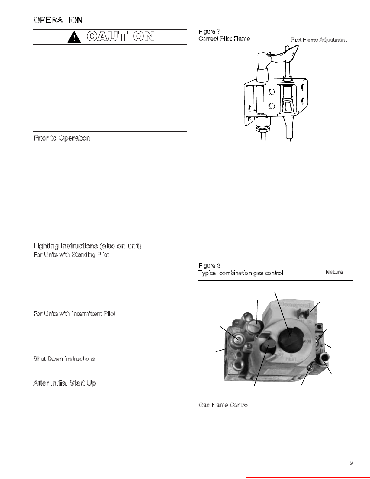
Figure 7
Correct Pilot Flame
The pilot burner is orificed to burn properly with an inlet
pressure of 6-7" W.C. on natural gas and 12-14" W.C. on
propane gas, but final adjustment must be made after
installation. Adjust to have a soft steady flame 3/4" to 1" long
and encompassing 3/8"-1/2" of the tip of the thermocouple or
flame sensing rod. Normally this flame will produce satisfactory
results. To adjust flame use pilot adjustment screw on
combination gas control (for location, see the combination gas
control literature supplied with unit). If the pilot flame is longer
and larger than shown by Figure 7, it is possible that it may
cause soot and/or impinge on the heat exchanger causing
burnout. If the pilot flame is shorter than shown it may cause
poor ignition and result in the controls not opening the
combination gas control. A short flame can be caused by a dirty
pilot orifice. Pilot flame condition should be observed
periodically to assure trouble-free operation.
P
ilot Flame Adjustment
Figure 8
N
Typical combination gas control
GAS CONTROL KNOB
PRESSURE REGULATOR
ADJUSTMENT SCREW
(UNDER CAP SCREW)
INLET
PRESSURE TAP
INLET
RESET BUTTON
PILOT ADJUSTMENT
SCREW
atural
ELECTRICAL
CONNECTION
TERMINALS
OUTLET
PRESSURE
TAP
OUTLET
PILOT TUBING
CONNECTION
Gas Flame Control
Control of burner flames on units utilizing natural gas is
achieved by moving the gas manifold to either increase or
decrease primary combustion air. Prior to flame adjustment,
operate unit with casing closed for about five minutes.
Operation can be viewed after loosening and pushing aside the
blue gas designation disc on rear of unit.
9
Heater Parts from ACF Greenhouses
 Loading...