

Modine Manufacturing MT28, MT30, MT33, MT56, MT60 Service Manual
...
WARNING
Improper installation, adjustment, alteration,
service or maintenance can cause property
damage, injury or death, and could cause
exposure to substances which have been
determined by various state agencies to cause
cancer, birth defects or other reproductive harm.
Read the installation, operating and
maintenance instructions thoroughly before
installing or servicing this equipment.
November, 2003
INSTALLATION AND SERVICE MANUAL
high intensity gas-fired infrared heaters
model MT
IMPORTANT
The use of this manual is specifically intended
for a qualified installation and service agency.
A qualified installation and service agency
must perform all installation and service of
these units.
THIS MANUAL IS THE PROPERTY OF THE OWNER.
PLEASE BE SURE TO LEAVE IT WITH THE OWNER WHEN YOU LEAVE THE JOB.
Inspection on Arrival
1. Inspect unit upon arrival. In case of damage, report it
immediately to the transportation company and your local
sales representative.
2.
Check rating plate on unit to verify that the power supply
meets available electric power at the point of installation.
3. Inspect unit upon arrival for conformance with description of
product ordered (including specifications where applicable).
9-500.3h
5H75283ALL
CAUTION
As with all infrared equipment, clearances to
combustible material are critical.
To prevent premature heat exchanger failure do
not locate ANY gas-fired units in areas where
chlorinated, halogenated, or acid vapors are
present in the atmosphere
FOR YOUR SAFETY
If you smell gas:
1. Open windows.
2. Don’t touch electrical switches.
3. Extinguish any open flame.
4. Immediately call your gas supplier.
FOR YOUR SAFETY
The use and storage of gasoline or other
flammable vapors and liquids in open containers
in the vicinity of this appliance is hazardous.
DANGER
Appliances must not be installed where they may be exposed
to potentially explosive or flammable atmosphere.
Special Precautions
THE INSTALLATION AND MAINTENANCE INSTRUCTIONS IN
THIS MANUAL MUST BE FOLLOWED TO PROVIDE SAFE,
EFFICIENT AND TROUBLE-FREE OPERATION. IN
ADDITION, PARTICULAR CARE MUST BE EXERCISED
REGARDING THE SPECIAL PRECAUTIONS LISTED BELOW.
FAILURE TO PROPERLY ADDRESS THESE CRITICAL
AREAS COULD RESULT IN PROPERTY DAMAGE OR LOSS,
PERSONAL INJURY, OR DEATH. THESE INSTRUCTIONS
ARE SUBJECT TO ANY MORE RESTRICTIVE LOCAL OR
NATIONAL CODES.
Hazard Intensity Levels
1. DANGER: Indicates an imminently hazardous
situation which, if not avoided, WILL result in death or
serious injury.
2. WARNING: Indicates a potentially hazardous
situation which, if not avoided, COULD result in death or
serious injury.
3. CAUTION: Indicates a potentially hazardous
situation which, if not avoided, MAY result in minor or
moderate injury.
4. IMPORTANT: Indicates a situation which, if not avoided,
MAY result in a potential safety concern.
Table of Contents
General Information .............................................................1
Inspection on Arrival ............................................................1
Special Precautions .............................................................2
SI (Metric) Conversion Factors............................................3
Unit Location........................................................................3
Location Recommendations .........................................3
Installation............................................................................3
Mounting .......................................................................3
Combustion/Ventilation Air Requirements.....................4
Gas Connections ..........................................................5
Electrical Connections ..................................................6
Start-Up Procedure..............................................................6
Pilot Flame Adjustment .................................................7
Main Burner Adjustment................................................7
Available Controls / Operating Sequence.....................8
Dimensions .........................................................................9
Maintenance ........................................................................9
Service & Troubleshooting.................................................10
Replacement Parts Ordering .............................................11
Model Number Designations.......................................11
Serial Number Designations .......................................11
Warranty.............................................................................12
CAUTION
1. Units are designed for indoor installation only. DO NOT
LOCATE UNITS OUTDOORS.
2. Purging of air from gas lines should be performed as
described in ANSI Z223.1 - latest edition “National Fuel
Gas Code”, or in Canada in CAN/CGA-B149 codes.
2
IMPORTANT
1. Approval requirements for infrared heaters specify that the
suspended type heaters shall be installed in accordance
with certain sections of the National Fire Codes published
by the National Fire Protection Association and various
ANSI standards. SOME of the requirements are listed
below.
Aircraft Hangars: Approval requirements are contained in
the current edition of ANSI/NFPA 409 (or in accordance
with the enforcing authority for Canada).
Public Garages: Approval requirements are contained in
the current edition of NFPA 88B (CAN/CGA B149 for
Canada).
Parking Structures: Approval requirements are contained
in the current edition of NFPA 88A.
General: All installations must be in accordance with the
current edition of ANSI Z-223.1 (NFPA 54) National Fuel
Gas Code and the current edition of the National Electric
Code, ANSI/NFPA 70. For Canada, installations must
conform with local building codes, or in the absence of
local codes, in accordance with the current edition of
CAN/CGA B149 and the Canadian Electric Code, C22.1.
2. Start-up and adjustment procedures should be performed
by a qualified service agency.
3. To check most of the Possible Remedies in the trouble
shooting guide listed in Tables 10.1 and 11.1, refer to the
applicable sections of the manual.
WARNING
1. All field gas piping must be pressure/leak tested prior to
operation. Never use an open flame; use a soap solution
or equivalent for testing.
2. Gas pressure to unit controls must never exceed 14"
W.C. (1/2 psi).
3. Disconnect power supply before making wiring
connections to prevent electrical shock and equipment
damage.
4. All units must be wired strictly in accordance with the
wiring diagram furnished with the unit. Any wiring
different from the wiring diagram could result in a hazard
to persons and property.
5. Any original factory wiring that requires replacement must
be replaced with wiring material having a temperature
rating of at least 105°C.
6. When servicing or repairing this equipment, use only
manufacturer-approved service replacement parts. A
complete replacement parts list may be obtained by
contacting Modine Manufacturing Company. Refer to the
rating plate on the unit for complete unit model number,
serial number, and company address. Any substitution of
non-approved parts or controls will be at the owner’s risk.
7. To prevent flame bail-out from the heater, the gas input to
the appliance, as indicated on the serial plate, must not
exceed the rated input by more than 5% or fall below the
rated input by more than 5%.
8. To prevent gas control circuit malfunction, the supply
voltage to the unit, as indicated on the serial plate must
not exceed or fall below the rated input voltage by more
than 5%.
IMPORTANT
Approval requirements for infrared heaters specify that the
suspended type heaters shall be installed in accordance
with certain sections of the National Fire Codes published
by the National Fire Protection Association and various
ANSI standards. SOME of the requirements are listed
below.
Aircraft Hangars: Approval requirements are contained in
the current edition of ANSI/NFPA 409 (or in accordance
with the enforcing authority for Canada).
Public Garages: Approval requirements are contained in
the current edition of NFPA 88B (CAN/CGA B149 for
Canada).
Parking Structures: Approval requirements are contained
in the current edition of NFPA 88A.
General: All installations must be in accordance with the
current edition of ANSI Z-223.1 (NFPA 54) National Fuel
Gas Code and the current edition of the National Electric
Code, ANSI/NFPA 70. For Canada, installations must
conform with local building codes, or in the absence of local
codes, in accordance with the current edition of CAN/CGA
B149 and the Canadian Electric Code, C22.1.
DANGER
Units must not be installed where they may be exposed to
potentially explosive or flammable atmosphere.
CAUTION
Units are designed for indoor installation only.
DO NOT LOCATE UNITS OUTDOORS.
To Convert Multiply By To Obtain
" W.C.
(inches water column)
0.24 kPa
psig 6.893 kPa
°F
subtract 32 and then
°C
multiply by 0.555
inches 25.4 mm
feet 0.305 meters
cfm (ft3/min) 0.028 m3/min
cfh (ft3/hr) 1.699 m3/min
Btu/ft
3
0.0374 mJ/m
3
pound 0.453 kg
Btu/hr 0.000293 kW/hr
gallons 3.785 liters
Table 3.1
SI (METRIC) CONVERSION FACTORS
UNIT LOCATION
SI (METRIC) CONVERSION FACTORS / UNIT LOCATION / INSTALLATION
Location Recommendations
1. When locating the heater, consider the general space and
heating requirements and availability of gas and electrical
supply.
2. Be sure the structural support and chain at the unit
location is adequate to support the weight of the unit.
3
Table 3.2
Combustible Material Clearances
➀➀
Minimum Clearances to Combustible Materials
(inches)
Top Sides Rear Bottom
MT28/30/33 30 30 24 72
MT56/60/66 36 36 33 88
MT84/90/99 48 42 39 104
MT112/120/132 54 48 45 120
MT160 60 54 51 136
Model
No.
3. Be sure that the minimum clearances to combustible
materials and for serving are maintained. The minimum
clearances to combustibles are shown in Table 3.2.
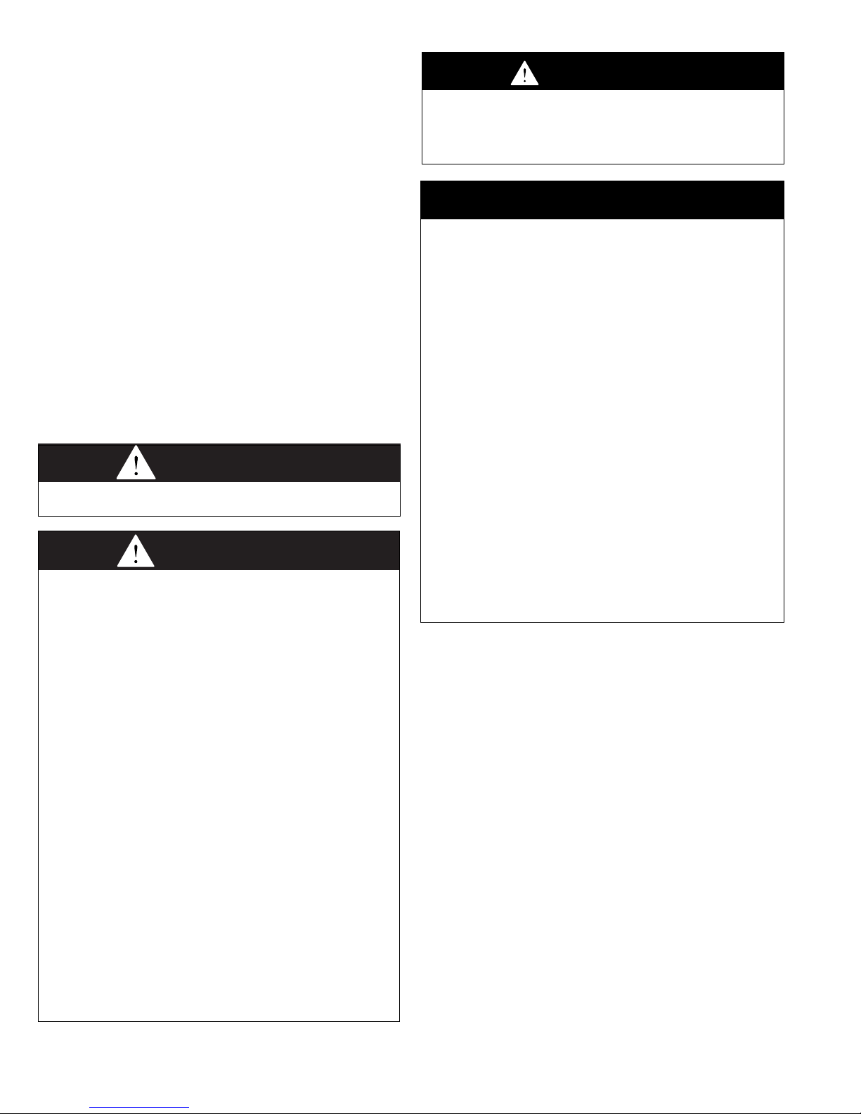
4. Mounting height (measured from the bottom of unit) at
which heaters are installed is critical. Please refer to
mounting height information in Table 4.1.
5. Do not locate units in areas where chlorinated,
halogenated, or acid vapors are present in the atmosphere.
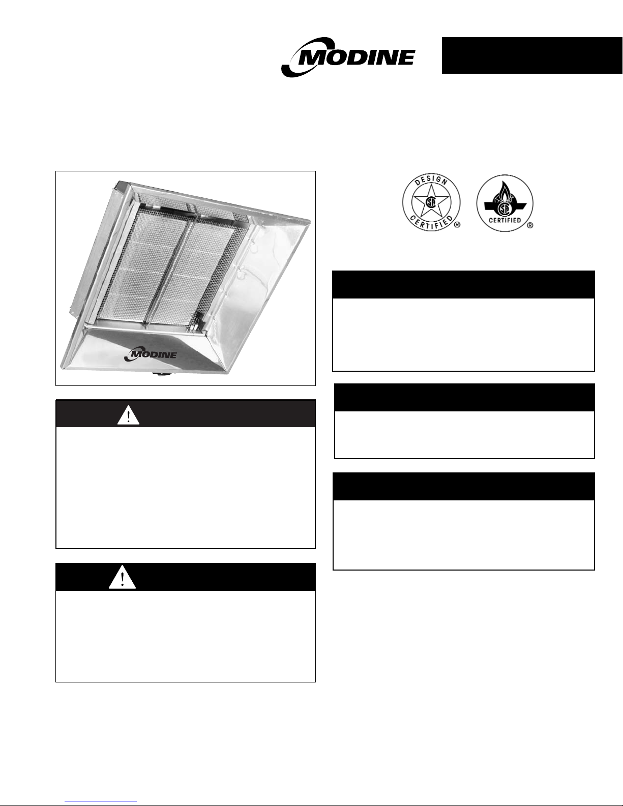
INSTALLATION
Mounting
Figures 4.2 and 4.3 illustrate typical rigid and chain mounting
arrangements, respectively, for a model MT infrared heater.
Check local codes for mounting requirements and use of flexible
gas connectors. Local codes may require rigid mounting. Heaters
must be mounted at angles from 10°to 35°from horizontal. The
gas manifold must be located on the low end of the heater, in a
horizontal position (parallel to the floor).
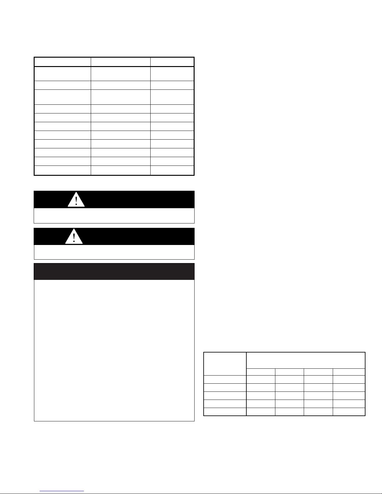
Where permissible, chain mounting is recommended. 5' chain
mounting sets are available as an accessory, allowing for 10° to
35° mounting angles. In the absence of this chain set, Number
1/0 Tenso chain (200 lb. working load) is recommended. “S”
hooks should be a minimum
1
/4" in diameter and the ends must
be closed after installation. Heaters located in aircraft hangers
or near overhead doors must be rigidly mounted to prevent
swinging. Under no circumstances should the gas supply line
or the electrical supply line to the heater be used to provide any
assistance in the suspension of the heater. Do not locate any
gas or electric service lines directly above or below the heater.
Insure that:
1. Clearances to combustibles (as shown on the rating plate
and in Table 3.2) are maintained.
2. For proper operation, the unit must be mounted on an angle
ten to thirty-five degrees (10°to 35°) from the horizontal
with the gas manifold located at the low end of the heater.
See Figure 4.1.
3. In locations used for storage of combustible materials,
signs shall be posted to specify the maximum permissible
stacking height to maintain required clearances from the
heater to the combustibles. See Figure 4.4.
4. Either gas piping or suspension mounting is flexible to
prevent fatigue failure from vibration or thermal expansion.
5. Adequate clearances to sprinkler heads are maintained.
➀ See figure 4.1 on page 4.
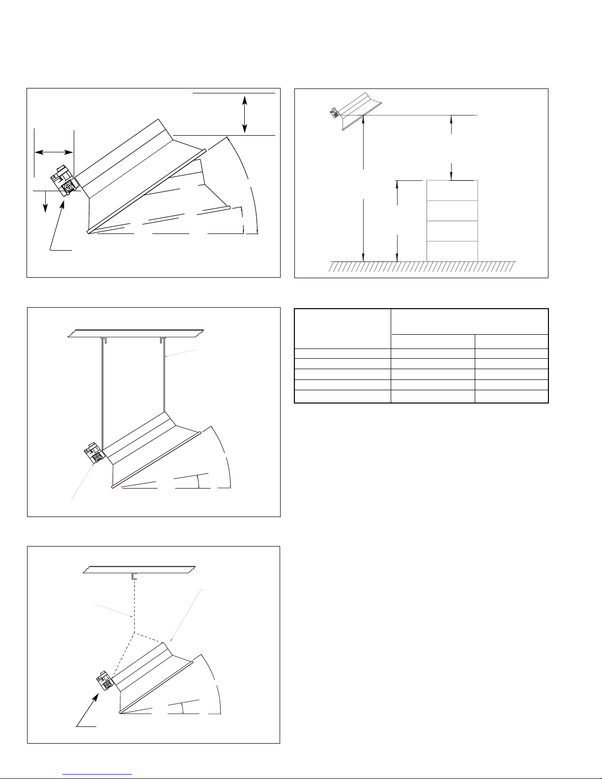
Figure 4.2
Typical Rigid Mounting Configuration
Figure 4.3
Typical Chain Mounting Configuration
Figure 4.4
Stacking Height
Table 4.1
Typical Mounting Height for Full Building Heating
INSTALLATION
Typical Mounting Height at Min/Max
Model No.
Mounting Angles (feet)
➀➀
10° 35°
MT28, 30, 33 8-14 7-12
MT56, 60, 66 14-20 12-16
MT84, 90, 99 20-26 16-24
MT112, 120, 132 26-32 20-30
MT160 26-40 22-38
➀➀
Mounting height values are recommendations only and may need to be
adjusted to meet requirements of actual installation.
4
e
OVERHEAD STRUCTURE AND FIELD CONNECTIONS MUST
N
G
l
t
d)
N
G
l
t
OVERHEAD STRUCTURE AND FIELD CONNECTIONS MUST
Figure 4.1
Combustible Material Clearances
REAR
BELOW
THE GAS MANIFOLD AND CONTROLS MUST BE
LOCATED AT THE LOW END OF THE HEATER
TOP
NOTE:
Gas manifold MUST be located on the low
side of the heater.
Combustion/Ventilation Air Requirements
Maintain positive air displacement of 4 cfm per 1000 Btu/hr for
natural gas and 5 cfm per 1000 Btu/hr for propane. The fresh
air supply must be located in the immediate proximity of the
unit(s). Fresh air intake openings are typically located high
on the building sidewalls at a comparable level to the heaters.
One square inch of net free inlet area per 1000 Btu/hr is
required. Multiple inlets, well distributed, should be used and
should direct air upward to prevent drafts at floor level. Inlets
are typically limited to 1 to 2 square feet in size.
It is recommended that units be interlocked with mechanical
exhaust fans for unvented applications. Mechanical exhaust
fans are typically located at high points of the building. For flat
roof areas, a series of small exhausters should be distributed
over the roof areas and interlocked with various heating zones.
BE ADEQUATE TO SUPPORT WEIGHT OF THE HEATER.
OTE:
as main and electrical
ines must not cross over
op of heater.
35˚ MAX.
10˚ MIN.
3/8" All thread rigid mount
(Used in aircraft hangers or
where draft conditions may b
expected.)
Minimum Clearance to
Combustible Materials
Mounting
Height
Stacking
Height
NOTE:
Gas manifold MUST be located
on the low side of the heater.
BE ADEQUATE TO SUPPORT WEIGHT OF THE HEATER.
OTE:
as main and electrical
ines must not cross over
op of heater.
5' Chain Mounting Set
Minimum
10˚
Horizontal Plane
'S' Hooks: 1/4" Dia. wire
(Crimp all 'S' hooks close
35˚ Maximum
Minimum
10˚
Horizontal Plane
35˚
Maximum
 Loading...