

WARNING
Improper installation, adjustment, alteration,
service or maintenance can cause property
damage, injury or death, and could cause
exposure to substances which have been
determined by various state agencies to cause
cancer, birth defects or other reproductive harm.
Read the installation, operating and
maintenance instructions thoroughly before
installing or servicing this equipment.
November, 2003
INSTALLATION AND SERVICE MANUAL
high intensity gas-fired infrared heaters
model MT
IMPORTANT
The use of this manual is specifically intended
for a qualified installation and service agency.
A qualified installation and service agency
must perform all installation and service of
these units.
THIS MANUAL IS THE PROPERTY OF THE OWNER.
PLEASE BE SURE TO LEAVE IT WITH THE OWNER WHEN YOU LEAVE THE JOB.
Inspection on Arrival
1. Inspect unit upon arrival. In case of damage, report it
immediately to the transportation company and your local
sales representative.
2.
Check rating plate on unit to verify that the power supply
meets available electric power at the point of installation.
3. Inspect unit upon arrival for conformance with description of
product ordered (including specifications where applicable).
9-500.3h
5H75283ALL
CAUTION
As with all infrared equipment, clearances to
combustible material are critical.
To prevent premature heat exchanger failure do
not locate ANY gas-fired units in areas where
chlorinated, halogenated, or acid vapors are
present in the atmosphere
FOR YOUR SAFETY
If you smell gas:
1. Open windows.
2. Don’t touch electrical switches.
3. Extinguish any open flame.
4. Immediately call your gas supplier.
FOR YOUR SAFETY
The use and storage of gasoline or other
flammable vapors and liquids in open containers
in the vicinity of this appliance is hazardous.
DANGER
Appliances must not be installed where they may be exposed
to potentially explosive or flammable atmosphere.
Special Precautions
THE INSTALLATION AND MAINTENANCE INSTRUCTIONS IN
THIS MANUAL MUST BE FOLLOWED TO PROVIDE SAFE,
EFFICIENT AND TROUBLE-FREE OPERATION. IN
ADDITION, PARTICULAR CARE MUST BE EXERCISED
REGARDING THE SPECIAL PRECAUTIONS LISTED BELOW.
FAILURE TO PROPERLY ADDRESS THESE CRITICAL
AREAS COULD RESULT IN PROPERTY DAMAGE OR LOSS,
PERSONAL INJURY, OR DEATH. THESE INSTRUCTIONS
ARE SUBJECT TO ANY MORE RESTRICTIVE LOCAL OR
NATIONAL CODES.
Hazard Intensity Levels
1. DANGER: Indicates an imminently hazardous
situation which, if not avoided, WILL result in death or
serious injury.
2. WARNING: Indicates a potentially hazardous
situation which, if not avoided, COULD result in death or
serious injury.
3. CAUTION: Indicates a potentially hazardous
situation which, if not avoided, MAY result in minor or
moderate injury.
4. IMPORTANT: Indicates a situation which, if not avoided,
MAY result in a potential safety concern.
Table of Contents
General Information .............................................................1
Inspection on Arrival ............................................................1
Special Precautions .............................................................2
SI (Metric) Conversion Factors............................................3
Unit Location........................................................................3
Location Recommendations .........................................3
Installation............................................................................3
Mounting .......................................................................3
Combustion/Ventilation Air Requirements.....................4
Gas Connections ..........................................................5
Electrical Connections ..................................................6
Start-Up Procedure..............................................................6
Pilot Flame Adjustment .................................................7
Main Burner Adjustment................................................7
Available Controls / Operating Sequence.....................8
Dimensions .........................................................................9
Maintenance ........................................................................9
Service & Troubleshooting.................................................10
Replacement Parts Ordering .............................................11
Model Number Designations.......................................11
Serial Number Designations .......................................11
Warranty.............................................................................12
CAUTION
1. Units are designed for indoor installation only. DO NOT
LOCATE UNITS OUTDOORS.
2. Purging of air from gas lines should be performed as
described in ANSI Z223.1 - latest edition “National Fuel
Gas Code”, or in Canada in CAN/CGA-B149 codes.
2
IMPORTANT
1. Approval requirements for infrared heaters specify that the
suspended type heaters shall be installed in accordance
with certain sections of the National Fire Codes published
by the National Fire Protection Association and various
ANSI standards. SOME of the requirements are listed
below.
Aircraft Hangars: Approval requirements are contained in
the current edition of ANSI/NFPA 409 (or in accordance
with the enforcing authority for Canada).
Public Garages: Approval requirements are contained in
the current edition of NFPA 88B (CAN/CGA B149 for
Canada).
Parking Structures: Approval requirements are contained
in the current edition of NFPA 88A.
General: All installations must be in accordance with the
current edition of ANSI Z-223.1 (NFPA 54) National Fuel
Gas Code and the current edition of the National Electric
Code, ANSI/NFPA 70. For Canada, installations must
conform with local building codes, or in the absence of
local codes, in accordance with the current edition of
CAN/CGA B149 and the Canadian Electric Code, C22.1.
2. Start-up and adjustment procedures should be performed
by a qualified service agency.
3. To check most of the Possible Remedies in the trouble
shooting guide listed in Tables 10.1 and 11.1, refer to the
applicable sections of the manual.
WARNING
1. All field gas piping must be pressure/leak tested prior to
operation. Never use an open flame; use a soap solution
or equivalent for testing.
2. Gas pressure to unit controls must never exceed 14"
W.C. (1/2 psi).
3. Disconnect power supply before making wiring
connections to prevent electrical shock and equipment
damage.
4. All units must be wired strictly in accordance with the
wiring diagram furnished with the unit. Any wiring
different from the wiring diagram could result in a hazard
to persons and property.
5. Any original factory wiring that requires replacement must
be replaced with wiring material having a temperature
rating of at least 105°C.
6. When servicing or repairing this equipment, use only
manufacturer-approved service replacement parts. A
complete replacement parts list may be obtained by
contacting Modine Manufacturing Company. Refer to the
rating plate on the unit for complete unit model number,
serial number, and company address. Any substitution of
non-approved parts or controls will be at the owner’s risk.
7. To prevent flame bail-out from the heater, the gas input to
the appliance, as indicated on the serial plate, must not
exceed the rated input by more than 5% or fall below the
rated input by more than 5%.
8. To prevent gas control circuit malfunction, the supply
voltage to the unit, as indicated on the serial plate must
not exceed or fall below the rated input voltage by more
than 5%.
IMPORTANT
Approval requirements for infrared heaters specify that the
suspended type heaters shall be installed in accordance
with certain sections of the National Fire Codes published
by the National Fire Protection Association and various
ANSI standards. SOME of the requirements are listed
below.
Aircraft Hangars: Approval requirements are contained in
the current edition of ANSI/NFPA 409 (or in accordance
with the enforcing authority for Canada).
Public Garages: Approval requirements are contained in
the current edition of NFPA 88B (CAN/CGA B149 for
Canada).
Parking Structures: Approval requirements are contained
in the current edition of NFPA 88A.
General: All installations must be in accordance with the
current edition of ANSI Z-223.1 (NFPA 54) National Fuel
Gas Code and the current edition of the National Electric
Code, ANSI/NFPA 70. For Canada, installations must
conform with local building codes, or in the absence of local
codes, in accordance with the current edition of CAN/CGA
B149 and the Canadian Electric Code, C22.1.
DANGER
Units must not be installed where they may be exposed to
potentially explosive or flammable atmosphere.
CAUTION
Units are designed for indoor installation only.
DO NOT LOCATE UNITS OUTDOORS.
To Convert Multiply By To Obtain
" W.C.
(inches water column)
0.24 kPa
psig 6.893 kPa
°F
subtract 32 and then
°C
multiply by 0.555
inches 25.4 mm
feet 0.305 meters
cfm (ft3/min) 0.028 m3/min
cfh (ft3/hr) 1.699 m3/min
Btu/ft
3
0.0374 mJ/m
3
pound 0.453 kg
Btu/hr 0.000293 kW/hr
gallons 3.785 liters
Table 3.1
SI (METRIC) CONVERSION FACTORS
UNIT LOCATION
SI (METRIC) CONVERSION FACTORS / UNIT LOCATION / INSTALLATION
Location Recommendations
1. When locating the heater, consider the general space and
heating requirements and availability of gas and electrical
supply.
2. Be sure the structural support and chain at the unit
location is adequate to support the weight of the unit.
3
Table 3.2
Combustible Material Clearances
➀➀
Minimum Clearances to Combustible Materials
(inches)
Top Sides Rear Bottom
MT28/30/33 30 30 24 72
MT56/60/66 36 36 33 88
MT84/90/99 48 42 39 104
MT112/120/132 54 48 45 120
MT160 60 54 51 136
Model
No.
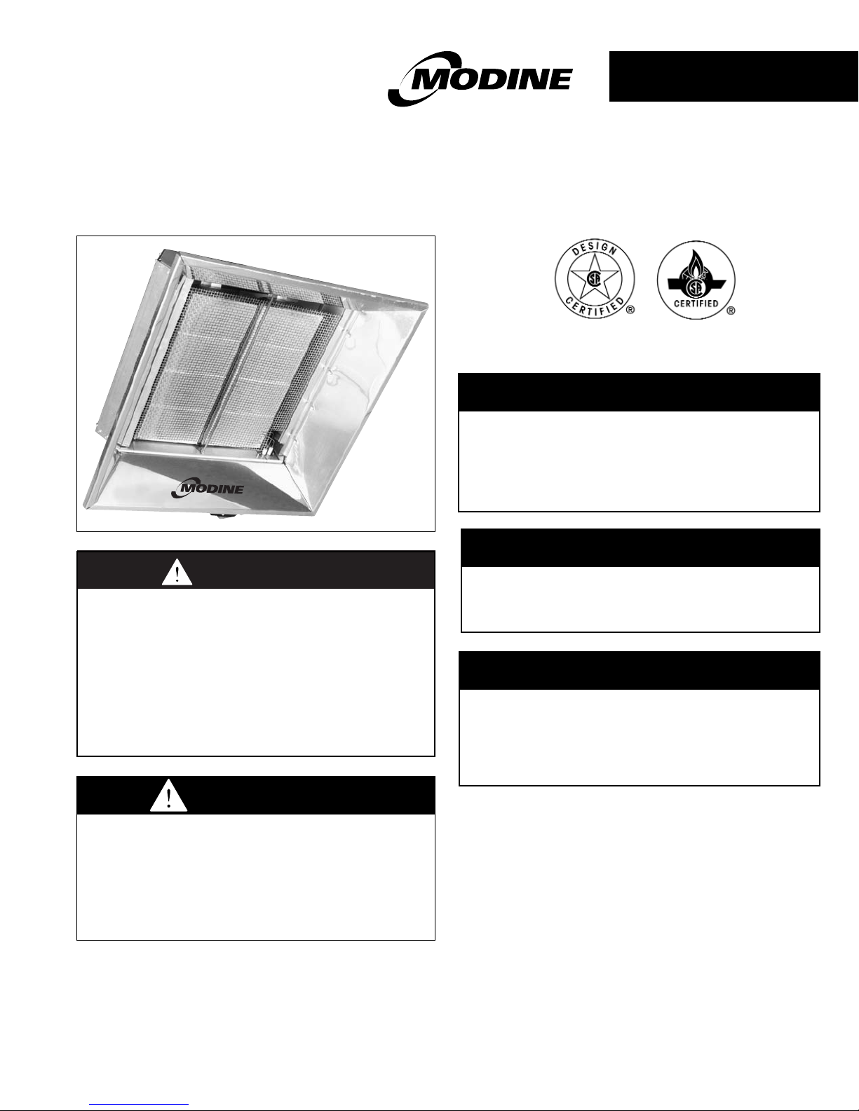
3. Be sure that the minimum clearances to combustible
materials and for serving are maintained. The minimum
clearances to combustibles are shown in Table 3.2.
4. Mounting height (measured from the bottom of unit) at
which heaters are installed is critical. Please refer to
mounting height information in Table 4.1.
5. Do not locate units in areas where chlorinated,
halogenated, or acid vapors are present in the atmosphere.
INSTALLATION
Mounting
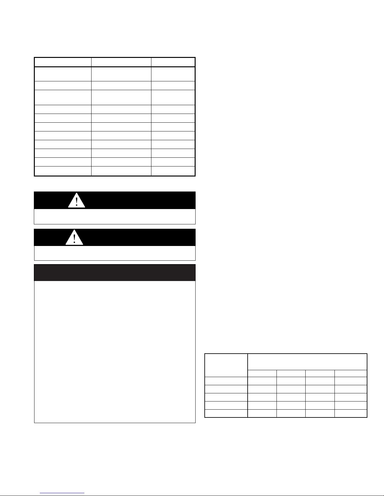
Figures 4.2 and 4.3 illustrate typical rigid and chain mounting
arrangements, respectively, for a model MT infrared heater.
Check local codes for mounting requirements and use of flexible
gas connectors. Local codes may require rigid mounting. Heaters
must be mounted at angles from 10°to 35°from horizontal. The
gas manifold must be located on the low end of the heater, in a
horizontal position (parallel to the floor).
Where permissible, chain mounting is recommended. 5' chain
mounting sets are available as an accessory, allowing for 10° to
35° mounting angles. In the absence of this chain set, Number
1/0 Tenso chain (200 lb. working load) is recommended. “S”
hooks should be a minimum
1
/4" in diameter and the ends must
be closed after installation. Heaters located in aircraft hangers
or near overhead doors must be rigidly mounted to prevent
swinging. Under no circumstances should the gas supply line
or the electrical supply line to the heater be used to provide any
assistance in the suspension of the heater. Do not locate any
gas or electric service lines directly above or below the heater.
Insure that:
1. Clearances to combustibles (as shown on the rating plate
and in Table 3.2) are maintained.
2. For proper operation, the unit must be mounted on an angle
ten to thirty-five degrees (10°to 35°) from the horizontal
with the gas manifold located at the low end of the heater.
See Figure 4.1.
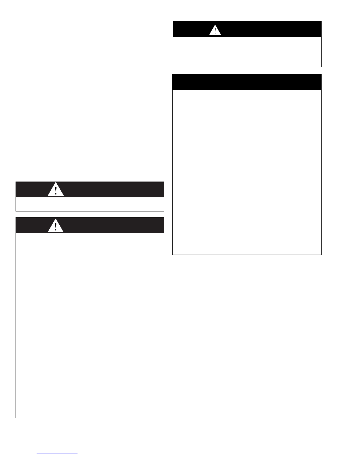
3. In locations used for storage of combustible materials,
signs shall be posted to specify the maximum permissible
stacking height to maintain required clearances from the
heater to the combustibles. See Figure 4.4.
4. Either gas piping or suspension mounting is flexible to
prevent fatigue failure from vibration or thermal expansion.
5. Adequate clearances to sprinkler heads are maintained.
➀ See figure 4.1 on page 4.
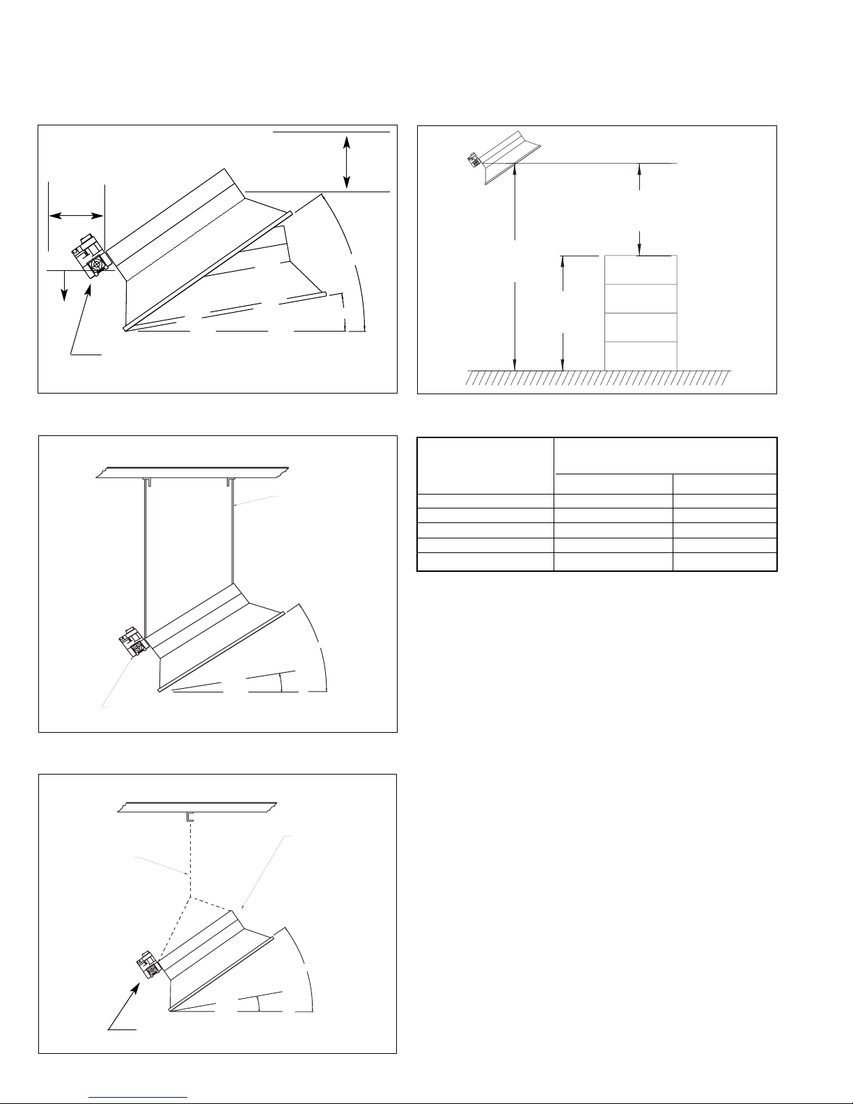
Figure 4.2
Typical Rigid Mounting Configuration
Figure 4.3
Typical Chain Mounting Configuration
Figure 4.4
Stacking Height
Table 4.1
Typical Mounting Height for Full Building Heating
INSTALLATION
Typical Mounting Height at Min/Max
Model No.
Mounting Angles (feet)
➀➀
10° 35°
MT28, 30, 33 8-14 7-12
MT56, 60, 66 14-20 12-16
MT84, 90, 99 20-26 16-24
MT112, 120, 132 26-32 20-30
MT160 26-40 22-38
➀➀
Mounting height values are recommendations only and may need to be
adjusted to meet requirements of actual installation.
4
e
OVERHEAD STRUCTURE AND FIELD CONNECTIONS MUST
N
G
l
t
d)
N
G
l
t
OVERHEAD STRUCTURE AND FIELD CONNECTIONS MUST
Figure 4.1
Combustible Material Clearances
REAR
BELOW
THE GAS MANIFOLD AND CONTROLS MUST BE
LOCATED AT THE LOW END OF THE HEATER
TOP
NOTE:
Gas manifold MUST be located on the low
side of the heater.
Combustion/Ventilation Air Requirements
Maintain positive air displacement of 4 cfm per 1000 Btu/hr for
natural gas and 5 cfm per 1000 Btu/hr for propane. The fresh
air supply must be located in the immediate proximity of the
unit(s). Fresh air intake openings are typically located high
on the building sidewalls at a comparable level to the heaters.
One square inch of net free inlet area per 1000 Btu/hr is
required. Multiple inlets, well distributed, should be used and
should direct air upward to prevent drafts at floor level. Inlets
are typically limited to 1 to 2 square feet in size.
It is recommended that units be interlocked with mechanical
exhaust fans for unvented applications. Mechanical exhaust
fans are typically located at high points of the building. For flat
roof areas, a series of small exhausters should be distributed
over the roof areas and interlocked with various heating zones.
BE ADEQUATE TO SUPPORT WEIGHT OF THE HEATER.
OTE:
as main and electrical
ines must not cross over
op of heater.
35˚ MAX.
10˚ MIN.
3/8" All thread rigid mount
(Used in aircraft hangers or
where draft conditions may b
expected.)
Minimum Clearance to
Combustible Materials
Mounting
Height
Stacking
Height
NOTE:
Gas manifold MUST be located
on the low side of the heater.
BE ADEQUATE TO SUPPORT WEIGHT OF THE HEATER.
OTE:
as main and electrical
ines must not cross over
op of heater.
5' Chain Mounting Set
Minimum
10˚
Horizontal Plane
'S' Hooks: 1/4" Dia. wire
(Crimp all 'S' hooks close
35˚ Maximum
Minimum
10˚
Horizontal Plane
35˚
Maximum

1. Installation of piping must conform with local building
codes, or in the absence of local codes, of the National
Fuel Gas Code, ANSI Z223.1 (NFPA 54) - Latest Edition. In
Canada, installation must be in accordance with CAN/CGAB149.1 for natural gas units and CAN/CGA-B149.2 for
propane units.
2. Piping to units should conform with local and national
requirements for type and volume of gas handled, and
pressure drop allowed in the line. Refer to Table 7.1 to
determine the cubic feet per hour (cfh) for the type of gas
and size of unit to be installed. Using this cfh value and the
length of pipe necessary, determine the pipe diameter from
Table 5.1. Where several units are served by the same
main, the total capacity, cfh and length of main must be
considered. Avoid pipe sizes smaller than 1/2". Table 5.1
allows for a 0.3" W.C. pressure drop in the supply pressure
from the building main to the unit. The inlet pressure to the
unit must be 7-14" W.C. for natural gas and 11-14" W.C. for
propane gas. When sizing the inlet gas pipe diameter,
make sure that the unit supply pressure can be met after
the 0.3" W.C. has been subtracted. If the 0.3" W.C.
pressure drop is too high, refer to the Gas Engineers
Handbook for other gas pipe capacities.
3. Install a ground joint union with brass seat and a manual
shut-off valve adjacent to the unit for emergency shut-off
and easy servicing of controls, including a 1/8" NPT
plugged tapping immediately upstream of the gas supply
connection to the heater, accessible for test gauge
connection. See Figure 5.1.
4. Installation of a sediment trap in the gas supply line before
each unit is required to minimize the possibility of loose
scale or dirt within the gas supply line entering the heater
gas control system. See Figure 5.1.
5. An approved flexible connector may be used (local codes
permitting) as a convenient method of connecting the
heaters to the gas supply and to avoid placing stress on
the gas supply line.
6. When pressure/leak testing pressures above 14" W.C. (1/2
psi), close the field installed shut-off valve, disconnect the
appliance, and its combination gas control from the gas
supply line, and plug the supply line before testing. When
testing pressures 14" W.C. (1/2 psi) or below, close the
manual shut-off valve on the appliance before testing.
Figure 5.1
Recommended Sediment Trap/Manual Shut-Off Valve
Installation
INSTALLATION
5
Gas Pipe Capacities (Up to 14" W.C. Gas Pressure through Schedule 40 Pipe)
Cubic Feet per Hour with Pressure Drop of 0.3" W.C.
Natural Gas Specific Gravity – 0.60, Propane Specific Gravity – 1.50
Length Pipe Diameter
Of Pipe 1/2" 3/4" 1" 1-1/4" 1-1/2" 2"
(feet) Natural Propane Natural Propane Natural Propane Natural Propane Natural Propane Natural Propane
10 132 83 278 175 520 328 1050 662 1600 1008 3050 1922
20 92 58 190 120 350 221 730 460 1100 693 2100 1323
30 73 46 152 96 285 180 590 372 890 561 1650 1040
40 63 40 130 82 245 154 500 315 760 479 1450 914
50 56 35 115 72 215 135 440 277 670 422 1270 800
60 50 32 105 66 195 123 400 252 610 384 1150 725
70 46 29 96 60 180 113 370 233 560 353 1050 662
80 43 27 90 57 170 107 350 221 530 334 990 624
90 40 25 84 53 160 101 320 202 490 309 930 586
100 38 24 79 50 150 95 305 192 460 290 870 548
125 34 21 72 45 130 82 275 173 410 258 780 491
150 31 20 64 40 120 76 250 158 380 239 710 447
Table 5.1
Gas Pipe Capacities
Gas Connections
WARNING
1. All field gas piping must be pressure/leak tested prior to
operation. Never use an open flame. Use a soap solution
or equivalent for testing.
2. Gas pressure to unit controls must never exceed 14"
W.C. (1/2 psi).
3. To prevent flame bail-out from the heater, the gas input
to the appliance as indicated on the serial plate, must not
exceed the rated input by more than 5% or fall below the
rated input by more than 5%.
SUPPLY LINE
GAS
SUPPLY LINE
3"
MIN.
GAS
SEDIMENT
TRAP
MANUAL GAS
SHUT-OFF VALVE
PLUGGED
1/8" NPT TEST
GAGE CONNECTION
GROUND
JOINT
UNION
W/ BRASS
SEAT
TO
CONTROLS

Electrical Connections
1. Installation of wiring must conform with local building codes,
or in the absence of local codes, of the National Electric
Code ANSI/NFPA 70 - Latest Edition. Unit must be
electrically grounded in conformance to this code. In
Canada, wiring must comply with CSA C22.1 Part 1,
Electrical Code.
2. The power supply to the unit should be protected with a
fused disconnect switch.
3. Provide only the voltage to the heater as stamped on the
heater serial plate. Do not provide external power to a
heater equipped with a millivolt, self-energizing control
system (Control Codes 27 or 67).
4. Heaters equipped with 25V controls (Control Codes 04, 48,
or 75) require a step-down transformer having a VA rating
in excess of the total connected electrical load.
5. The heater is not to be energized until gas is available at
the heater. Failure to observe this point may result in failure
of control components.
6. Wiring must not be located directly above or below the
heater to avoid overheating of the wires. The wires must
not touch the sides of the heater.
7. Control wire used to connect the heater to the thermostat
must have adequate ampacity and insulation temperature
rating for the total connected load.
START-UP PROCEDURE
1. Turn off power to the unit at the disconnect switch. Check
that fuses or circuit breakers are in place and sized
correctly. Turn all hand gas valves to the “OFF” position.
2. Check that the supply voltage matches the unit supply
voltage listed on the serial plate. Verify that all wiring is
secure and properly protected. Trace circuits to insure the
unit has been wired according to the wiring diagram.
3. Verify that there is adequate ventilation for intake of fresh
air and exhaust of products of combustion.
4. Perform a visual inspection of the unit to make sure no
damage has occurred during installation.
5. Recheck the gas supply pressure. The inlet pressure to the
unit must be 7-14" W.C. for natural gas and 11-14" W.C. for
propane gas. The gas supply pressure must never exceed
14" W.C. If the pressure exceeds 14" W.C., a gas pressure
regulator must be added upstream of the combination gas
valve.
6. Open the field installed manual shut-off valve and turn
power on to the unit.
7. Follow the procedure on the heater’s Lighting Instruction
Label to put the heater into operation. Be certain the gas
line is purged of air prior to attempting to operate the unit.
8. For units equipped with a pilot, check the pilot flame length
(See Pilot Flame Adjustment section).
9. Check to make sure that the main gas valve opens upon a
call for heat from the thermostat.
10. Check to insure that gas controls sequence properly (See
Control Operating Sequence, page 8).
CAUTION
Purging of air from gas lines should be performed as
described in ANSI Z223.1 - Latest Edition “National Fuel Gas
Code”, or in Canada, CAN/CGA-B149 codes.
6
INSTALLATION / START-UP PROCEDURE
WARNING
Disconnect power supply before making wiring connections to
prevent electrical shock and equipment damage.
All units must be wired strictly in accordance with wiring
diagram furnished with the unit. Any wiring different from the
wiring diagram could result in a hazard to persons and
property.
Any original factory wiring that requires replacement must be
replaced with wiring material having a temperature rating of at
least 105°C.
To prevent gas control circuit malfunction, the voltage to the
unit, as indicated on the serial plate, must not exceed or fall
below the rated input voltage by more than 5%.
IMPORTANT
Start-up and adjustment procedures should be performed by a
qualified service agency.

7
START-UP PROCEDURE
Pilot Flame Adjustment (Intermittent Pilot and
Millivolt Standing Pilot control systems – Control
Codes 04, 08, 27, and 67
The pilot burner is orificed to burn properly with an inlet
pressure of 7-14" W.C. on natural gas and 11-14" W.C. on
propane gas, but final adjustment must be made after
installation. If the pilot flame is too long or large, it is possible
that it may cause soot on the burner assembly. If the pilot flame
is shorter than shown, it may cause poor ignition and result in
the controls not opening the combination gas control. A dirty
pilot orifice may cause a short flame. Pilot flame condition
should be observed periodically to assure trouble-free
operation.
To adjust the pilot flame:
1. Create a call for heat from the thermostat.
2. Remove the cap from the pilot adjustment screw. For
location, see the combination gas control literature supplied
with unit.
3. Adjust the pilot flame length by turning the screw in or out
to achieve a soft steady flame 3/4" to 1" long and
encompassing 3/8"-1/2" of the tip of the flame sensing rod
or power-pile (See Figure 7.1).
4. Replace the cap from the pilot adjustment screw.
Main Burner Adjustment
The gas pressure regulator (integral to the combination gas
control) is adjusted at the factory for average gas conditions.
It is important that gas be supplied to the heater in accordance
with the input rating on the serial plate. Actual input should be
checked and necessary adjustments made after the heater is
installed. Over-firing, a result of too high an input, reduces the life
of the appliance and increases maintenance. Under no
circumstances should the input exceed that shown on the serial
plate.
Measuring the manifold pressure is done at the test port on the
main gas valve on the unit (See Figure 7.2).
To adjust the manifold pressure:
1. The correct manifold pressure is 6" W.C. for natural gas
and 10" W.C. for propane gas. Adjust the main gas
pressure regulator spring to achieve the proper manifold
pressure (see Figure 7.2).
2. Move the field installed manual shut-off valve to the “OFF”
position.
3. Remove the 1/8" pipe plug in the gas valve adjacent to the
manifold and attach a water manometer of “U” tube type
that is at least 12" high.
4. Move the field installed manual shut-off valve to the “ON”
position.
5. Create a call for heat from the thermostat.
6. After adjustment, move the field installed manual shut-off
valve to the “OFF” position and replace the 1/8" pipe plug.
7. After the plug is in place, move the field installed manual
shut-off valve to the “ON” position and recheck pipe plugs
for gas leaks with a soap solution.
Figure 7.1
Correct Pilot Flame (Millivolt Powerpile shown)
Figure 7.2
Gas Valve Features
Pilot Adjustment
Screw (Under Cap)
Regulator Adjustment
Screw (Under Cap)
Plugged Outlet
Pressure Tap
Pilot Line
Connectio
n
Control
Knob
Type of Gas Natural Propane
Model
Btu/Ft.
3
1040 2500 No. of
Size
Specific Gravity 0.60 1.53 Orifices
Manifold Pressure In. W.C. 6.0 10
MT-28
cfh 26.4 -
1
Orifice Drill Size #43 -
MT-30
cfh 28.8 12.0
1
Orifice Drill Size #42 #52
MT-33
cfh 32.2 -
1
Orifice Drill Size #41 -
MT-56
cfh 52.9 -
2
Orifice Drill Size #43 -
MT-60
cfh 57.7 24.0
2
Orifice Drill Size #42 #52
MT-66
cfh 64.4 -
2
Orifice Drill Size #41 -
MT-84
cfh 79.3 -
3
Orifice Drill Size #43 -
MT-90
cfh 86.5 36.0
3
Orifice Drill Size #42 #52
MT-99
cfh 96.6 -
3
Orifice Drill Size #41 -
MT-112
cfh 105.8 -
4
Orifice Drill Size #43 -
MT-120
cfh 115.4 48.0
4
Orifice Drill Size #42 #52
MT-132
cfh 128.8 -
4
Orifice Drill Size #41 -
MT-160
cfh 153.8 64.0
4
Orifice Drill Size #38 #49
Table 7.1
Manifold Pressure and Gas Consumption

8
Control Systems Options
The MT series infrared heaters are available with a choice of
three different gas control options. The available controls and
associated control codes are (see Table 8.1 for description of
Control Codes):
• Direct spark ignition with 100% safety lockout with manual
reset
Natural Gas – Control Code 47 or 48
Propane Gas – Control Code 97 or 75
• Intermittent pilot ignition with non-100% shut-off
Natural Gas only – Control Code 08 or 04
• Millivolt, self-energizing with standing pilot and 100% safety
shutoff
Natural Gas – Control Code 27
Propane Gas – Control Code 67
Control Operating Sequence
Direct Spark Ignition Gas Controls – Control Codes
47, 48, 97, and 75
Utilizes a single-stage combination gas control, an ignition
control, and a single-stage thermostat.
1. The thermostat calls for heat.
2. The main gas valve opens and the spark igniter sparks in
an attempt to light the gas at the ceramic burner.
3. Once the burner is lit, the flame sensor proves ignition and
stops the spark igniter from sparking. If ignition is not
proven (the burner does not light) within 15 seconds, the
system will lockout, de-energizing the gas valve and ignition
control system. If the system locks out, it may be reset by
an interruption of the power source. The system will then
attempt to light the burner, if a call for heat from the
thermostat remains.
4. The unit continues to operate until the thermostat is
satisfied, at which time the main gas valve closes 100%
and the unit shuts off.
Intermittent Pilot Ignition with Non-100% Shut-Off
Gas Controls – Control Codes 08 and 04
Utilizes a single-stage combination gas control, an ignition
control, and a single-stage thermostat.
1. The thermostat calls for heat.
2. The pilot gas valve opens and the pilot spark igniter sparks
in an attempt to light the pilot.
3. The pilot flame sensor attempts to prove pilot ignition. If the
pilot does not light, ignition sparking and pilot gas flow will
continue until the pilot flame is established.
4. Once the pilot is lit, the pilot flame sensor proves ignition
and stops the spark igniter from sparking. At the same time
the main gas valve is opened and the ceramic burner is lit.
The unit continues to operate until the thermostat is
satisfied, at which time the main gas and pilot gas valves
are closed 100% and the unit shuts off.
Millivolt, Self-Energizing with Standing Pilot and
100% Safety Shutoff Gas Controls – Control Codes
26 and 67
Utilizes a single-stage combination gas control and a singlestage millivolt thermostat.
1. The pilot is manually lighted with the gas valve control knob
depressed in the PILOT position and held (approximately 1
minute) until the millivolt generator is heated sufficiently to
keep the pilot valve open. The control knob is then turned
to the ON position.
2. Upon a call for heat, the millivolt thermostat contacts close,
completing the circuit to the gas valve. The gas valve will
open and the ceramic burner is lit from the standing pilot.
3. Once the millivolt thermostat is satisfied, the main gas valve
closes 100% and the unit shuts off, with the pilot valve
remaining open with a standing pilot.
4. If the pilot goes out, the millivolt generator will cool and
interrupt the circuit to the pilot valve. Both the pilot and
main gas valves are closed 100%. The unit remains
inactive until step 1 is repeated.
START-UP PROCEDURE
Table 8.1
Performance and Available Control Systems
➀ ➁
➀ Model MT high intensity infrared heaters with direct spark or intermittent pilot ignition are equipped with 25 volt controls.
➁ Control codes specified for line voltage supply include 115V/25V step-down transformers.
Direct Spark Ignition of Burner
➀
Intermittent Pilot
➀
Millivolt, Self Energizing
100% Safety Lockout with Manual Reset Non 100% Shut Off Standing Pilot, 100% Safety Shut Off
Control Code - Supply/Thermostat Voltage Control Code - Supply/Thermostat Voltage Control Code - Thermostat Voltage
Natural Gas Propane Gas Natural Gas Natural Gas Propane Gas
Model No.
47 - 115V ➁ 48 - 25V 97 - 115V ➁ 75 - 25V 08 - 115V ➁ 04 - 25V 27 - Millivolt 67 - Millivolt
MT-28
••
N/A N/A
•• •
N/A
MT-30
•••• • • • •
MT-33
••
N/A N/A
•• •
N/A
MT-56
••
N/A N/A
•• •
N/A
MT-60
•••• • • • •
MT-66
••
N/A N/A
•• •
N/A
MT-84
••
N/A N/A
•• •
N/A
MT-90
•••• • • • •
MT-99
••
N/A N/A
•• •
N/A
MT-112
••
N/A N/A
•• •
N/A
MT-120
•••• • • • •
MT-132
••
N/A N/A
•• •
N/A
MT-160
••••
N/A N/A N/A N/A

9
DIMENSIONS / MAINTENANCE
Figure 9.1
Unit Drawing
Table 9.1
Dimensions
Dimensions Radiating Shipping
(Inches) Area Weight
A B (Sq. Inches) (Lbs.)
MT28,30,33 17.12 7.63 93 30
MT56,60,66 24.00 14.44 186 40
MT84,90,99 30.75 21.25 279 48
MT112,120,132,160 37.58 28.08 372 59
Model
Numbers
Note: All models except MT160 include a secondary re-radiating grid screen (shown in drawing above).
MAINTENANCE
All heating equipment should be serviced before each
heating season to assure proper operation. The following
items may require more frequent service based on the
environment in which the unit is installed, and how long
the unit is operated.
Burner Assembly
Disconnect all electrical power to the heater and close
the gas supply valve installed adjacent to the heater.
With an air hose regulated to 15 psig maximum, blow
off any dust and dirt that has accumulated on the heater,
by blowing across the ceramic burner (not directly at the
ceramic burner). Do not insert the air hose into the inlet
of each venturi tube.
Burner Orifice
Remove each burner orifice, clean, and reinstall on the
heater manifold. Drill sizes can be found in Table 7.1.
Pilot Assembly (not applicable for Direct Spark Ignition)
Remove the pilot burner assembly. With an air hose regulated to 15
psig maximum, blow the assembly clean and replace in the original
position.
Electrical Wiring
The electrical wiring should be checked annually for loose
connections or deteriorated insulation.
Gas Piping & Controls
The gas valves and piping should be checked annually for
general cleanliness and tightness. The gas controls should be
checked to insure that the unit is operating properly.
A
B
23.75
16.13
4X .312 Dia Mounting Holes
9.00
4.75
17.00

No Gas 1. Main gas is off. 1. Open manual gas valve.
2. Power supply is off. 2. Turn on main power.
3. Air in gas line. 3. Purge gas line.
4. External regulator malfunctioning. 4. Replace external regulator.
5. External regulator reversed. 5. Remove and install regulator properly.
Pilot does not light 1. Main gas is off. 1. Open gas shut-off valve.
2. Power supply is off. 2. Turn on main power.
3. Air in gas line. 3. Purge gas line.
4. Dirt in pilot orifice. 4. Check for plugged pilot orifice and clean
with compressed air if necessary.
5. Gas pressure out of proper range. 5. Adjust to a maximum of 14" W.C.
Minimum for Natural Gas - 7" W.C.
Minimum for Propane Gas - 11" W.C.
6. Pilot valve does not open. 6. Check wiring for 24 volts to valve.
Defective ignition controller or gas valve.
7. No spark at igniter. 7.
a. Loose wire connections. a. Check all ignition controller wiring.
b. Pilot sensor is grounded. b. Replace sensor if cracked or worn.
c. Defective ignition controller. c. Replace ignition controller.
Pilot goes out on 100% 1. Defective pilot interrupter in combination gas 1. Replace combination gas valve.
shut-off when hold down valve .
button is released 2. Defective pilot flame sensor. 2. Replace pilot flame sensor.
3. Insufficient heat on pilot flame sensor. 3. Check pilot orifice for size. Clean pilot burner.
4. Improper pilot flame sensor location. 4. Check position with respect to pilot.
5. Connection is poor contact at valve end of the 5. Insure clean and tight contact.
sensing element.
6. Low gas pressure. 6. Provide proper gas pressure.
Main burners do not light 1. Defective valve. 1. Replace valve.
(Pilot is lit) 2. No electrical power to gas valve. 2. Check wiring to gas valve.
3. Defective pilot sensor. 3. Replace pilot sensor.
4. Defective ignition controller. 4. Replace ignition controller.
5. Improper thermostat wiring. 5. Verify wiring compared to diagram.
6. Manual valve closed on combination gas valve. 6. Turn knob to ON position on combination
gas valve.
Direct spark fails to ignite 1. Electrode improperly located 1. Relocate to correct position.
main burner(s) 2. Electrode ceramic cracked 2. Replace electrode
3. Electrode wire is loose, broken, or frayed. 3. Reconnect loose wire or replace broken or
frayed wire and/or electrode.
4. Low manifold gas pressure. 4. Provide proper gas pressure.
5. Gas valve fails to open. 5. Replace gas valve.
6. Ignition detection control defective. 6. Replace ignition control module.
Flashback (burning of 1. Heater mounted at incorrect angle. 1. Angle to be 10
°
to 35°from horizontal.
gas/air mixture inside 2. Excessive drafts. 2. Shield or relocate heater from drafts.
plenum) 3. Gas leak at manifold, gas valve, and/or pilot 3. Check all connections with soap solution
tube connections. and tighten as necessary.
4. Separation of ceramic tiles. 4. Replace burner assembly.
5. Ceramic grid(s) cracked. 5. Replace burner assembly.
Unit cycles off and on 1. Insufficient heat on pilot element. 1. Check pilot orifice, clean pilot burner.
2. Excessive drafts. 2. Shield or relocate unit from drafts.
10
SERVICE & TROUBLESHOOTING
Table 10.1 - Troubleshooting
Trouble Possible Cause Possible Remedy
IMPORTANT
To check most of the Possible Remedies in the troubleshooting
guide listed in Tables 10.1 and 11.1, refer to the applicable
sections of the manual.
CAUTION
Do not attempt to reuse any mechanical or electrical
controllers which have been wet. Replace defective controller.
WARNING
When servicing or repairing this equipment, use only factoryapproved service replacement parts. A complete replacement
parts list may be obtained by contacting Modine Manufacturing
Company. Refer to the rating plate on the appliance for
complete appliance model number, serial number, and
company address. Any substitution of parts or controls not
approved by the factory will be at the owner’s risk.

11
Table 11.1
Troubleshooting Continued
SERVICE & TROUBLESHOOTING / REPLACEMENT PARTS ORDERING
Heater will not turn off 1. Defective thermostat. 1. Repair or replace thermostat.
2. Gas valve stuck open. 2. Replace gas valve.
3. Unit undersized. 3. Check design conditions. If the unit is
undersized, additional heater(s) may be
required.
Dark spots on ceramic 1. Foreign matter behind the ceramic tile(s). 1. Clean ceramic tiles or replace.
Carbon formation on 1. Misaligned orifice. 1. Replace orifice.
ceramic surface of 2. Pilot depositing carbon. 2. Clean pilot burner, check pilot orifice.
burner 3. Obstruction in venturi tube. 3. Clean with a soft brush.
4. Low gas pressure. 4. Provide proper gas pressure.
5. Wrong gas supplied to the heater. 5. Check label for gas required.
Low heater output 1. Low inlet or manifold gas pressure 1. Adjust for proper gas pressure.
2. Orifice partially blocked with foreign matter. 2. Remove orifice, clean, and reinstall.
3. Products of combustion not adequately vented. 3. Provide adequate ventilation for products
of combustion.
4. Manifold misaligned from excessive torque 4. Replace the manifold.
applied at time of gas pipe installation.
5. Foreign matter in venturi tube. 5. Clean with a soft brush.
6. Gas supply piping too small. 6. Replace piping or increase gas supply
pressure.
7. Unit undersized. 7. Check design conditions. If unit is
undersized, an additional unit(s) or other
heat source must be added.
Gas odor 1. Loose pipe connection. 1. Check all connections with a soap solution
and tighten as necessary.
Control assembly 1. Heater not mounted correctly. 1. Angle to be 10
°
to 35°from horizontal.
overheating 2. Heater mounted too close to ceiling. 2. Check to main
t
ain proper top clearance.
Trouble Possible Cause Possible Remedy
For Servicing
If a qualified service person cannot solve a problem with the installation, please consult with your local gas company or
sales representative.
When servicing, repairing or replacing parts on these units, locate the model identification plate of the unit and always give the
complete Model Number and Serial Number from the model identification plate. The serial plate is located on the side of the
reflector. For a complete description of the Model Number or Serial Number, see Figures 11.1 and 11.2.
MT 30 G 47
Figure 11.1
Model Number Designations
Figure 11.2
Serial Number Designations
MT
High Intensity
Infrared Heater
Ignition
G - Spark Ignition
C - Standing Pilot, Millivolt System
Model
28
30
33
56
60
66
84
90
99
112
120
132
160
Control Code
Direct Spark Ignition
47 - Natural Gas, 115V
48 - Natural Gas, 25V
97 - Propane Gas, 115V
75 - Propane Gas, 25V
Intermittent Pilot Ignition
04 - Natural Gas, 25V
08 - Natural Gas, 115V
Millivolt, Self-Energizing
27 - Natural Gas, Millivolt
67 - Propane Gas, Millivolt
101 26 99 - 1256
SEQUENCE
NUMBER
YEAR OF
MANUFACTURE
99 – 1999
00 – 2000
etc.
WEEK OF
MANUFACTURE
01 – 1st week of year
26 – 26th week of year
SERIES IDENTITY
NUMBER
Identifies series of controls

Seller warrants its products to be free from defects in material and workmanship,
EXCLUSIVE, HOWEVER, of failures attributable to the use of materials substituted
under emergency conditions for materials normally employed. This warranty covers
replacement of any parts furnished from the factory of Seller, but does not cover
labor of any kind and materials not furnished by Seller, or any charges for any
such labor or materials, whether such labor, materials or charges thereon are due
to replacement of parts, adjustments, repairs, or any other work done. This
warranty does not apply to any equipment which shall have been repaired or
altered outside the factory of Seller in any way so as, in the judgment of Seller, to
affect its stability, nor which has been subjected to misuse, negligence, or
operating conditions in excess of those for which such equipment was designed.
This warranty does not cover the effects of physical or chemical properties of water
or steam or other liquids or gases used in the equipment.
BUYER AGREES THAT SELLER’S WARRANTY OF ITS PRODUCTS TO BE
FREE FROM DEFECT IN MATERIAL AND WORKMANSHIP, AS LIMITED
HEREIN, SHALL BE IN LIEU OF AND EXCLUSIVE OF ALL OTHER
WARRANTIES, EITHER EXPRESS OR IMPLIED, WHETHER ARISING FROM
LAW, COURSE OF DEALING, USAGE OF TRADE, OR OTHERWISE, THERE
ARE NO OTHER WARRANTIES, INCLUDING WARRANTY OF
MERCHANTABILITY OR FITNESS FOR PURPOSE,WHICH EXTEND BEYOND
THE PRODUCT DESCRIPTION CONFIRMED BY BUYER AND SELLER AS OF
THE DATE OF FINAL AGREEMENT.
This warranty is void if the input to the product exceeds the rated input as
indicated on the product serial plate by more than 5% on gas-fired and oil-fired
units, or if the product in the judgment of SELLER has been installed in a corrosive
atmosphere, or subjected to corrosive fluids or gases, been subjected to misuse,
negligence, accident, excessive thermal shock, excessive humidity, physical
damage, impact, abrasion, unauthorized alterations, or operation contrary to
SELLER’S printed instructions, or if the serial number has been altered, defaced or
removed.
Heat Exchangers
For Seller’s non-sep
arated combustion Gas-Fired Unit Heaters
BUYER’S REMEDY FOR BREACH OF WARRANTY, EXCLUSIVE OF ALL
OTHER REMEDIES PROVIDED BY LAW, IS LIMITED TO REPAIR OR
REPLACEMENT AT THE FACTORY OF SELLER, ANY HEAT EXCHANGER
WHICH SHALL, WITHIN TEN YEARS FROM DATE OF FIRST BENEFICIAL
USE BY BUYER OR ANY OTHER USER, WITHIN TEN YEARS FROM DATE
OF RESALE BY BUYER OR ANY OTHER USER, WITHIN TEN YEARS
FROM DATE OF RESALE BY BUYER IN ANY UNCHANGED CONDITION,
OR WITHIN ONE HUNDRED TWENTY-SIX MONTHS FROM DATE OF
SHIPMENT FROM SELLER, WHICHEVER OCCURS FIRST, BE RETURNED
TO SELLER WITH TRANSPORTATION CHARGES PREPAID AND WHICH
THE EXAMINATION OF SELLER SHALL DISCLOSE TO HAVE BEEN
DEFECTIVE; EXCEPT THAT WHEN THE PRODUCT IS TO BE USED BY
BUYER AS A COMPONENT PART OF EQUIPMENT MANUFACTURED BY
BUYER, BUYER’S REMEDY FOR BREACH, AS LIMITED HEREIN, SHALL
BE LIMITED TO ONE YEAR FROM DATE OF SHIPMENT FROM SELLER.
FOR GAS-FIRED PRODUCTS INSTALLED IN HIGH HUMIDITY
APPLICATIONS AND UTILIZING STAINLESS STEEL HEAT EXCHANGERS,
BUYER’S REMEDY FOR BREACH, AS LIMITED HEREIN, SHALL BE
LIMITED TO TEN YEARS FROM DATE OF SHIPMENT FROM SELLER.
For Seller's Low Intensity Gas-Fired Infrared Heaters
BUYER'S REMEDY FOR BREACH OF WARRANTY, EXCLUSIVE OF ALL
OTHER REMEDIES PROVIDED BY LAW, IS LIMITED TO REPAIR OR
REPLACEMENT AT THE FACTORY OF SELLER, ANY HEAT EXCHANGER
WHICH SHALL, WITHIN FIVE YEARS FROM DATE OF FIRST BENEFICIAL
USE BY BUYER OR ANY OTHER USER, WITHIN FIVE YEARS FROM DATE
OF RESALE BY BUYER OR ANY OTHER USER, WITHIN FIVE YEARS
FROM DATE OF RESALE BY BUYER IN ANY UNCHANGED CONDITION,
OR WITHIN 66 MONTHS FROM DATE OF SHIPMENT FROM SELLER,
WHICHEVER OCCURS FIRST, BE RETURNED TO SELLER WITH
TRANSPORTATION CHARGES PREPAID AND WHICH THE EXAMINATION
OF SELLER SHALL DISCLOSE TO HAVE BEEN DEFECTIVE; EXCEPT THAT
WHEN THE PRODUCT IS TO BE USED BY BUYER AS A COMPONENT
PART OF EQUIPMENT MANUFACTURED BY BUYER, BUYER'S REMEDY
FOR BREACH, AS LIMITED HEREIN, SHALL BE LIMITED TO ONE YEAR
FROM DATE OF SHIPMENT FROM SELLER.
Heat Exchanger (Condensers) for all Seller’s products except nonseparated comb
ustion Gas-Fired Unit Heaters and Infrared Heaters, all
Burners except Infrared Heaters, and Sheet Metal for all Seller's products
BUYER’S REMEDY FOR BREACH OF WARRANTY, EXCLUSIVE OF ALL
OTHER REMEDIES PROVIDED BY LAW, IS LIMITED TO REPAIR OR
REPLACEMENT AT THE FACTORY OF SELLER, ANY HEAT EXCHANGER
(CONDENSER) OR BURNER WHICH SHALL, WITHIN ONE YEAR FROM
DATE OF FIRST BENEFICIAL USE BY BUYER OR ANY OTHER USER,
WITHIN ONE YEAR FROM DATE OF RESALE BY BUYER IN ANY
UNCHANGED CONDITION, OR WITHIN EIGHTEEN MONTHS FROM DATE
OF SHIPMENT FROM SELLER, WHICHEVER OCCURS FIRST, BE
RETURNED TO SELLER WITH TRANSPORTATION CHARGES PREPAID
AND WHICH THE EXAMINATION OF SELLER SHALL DISCLOSE TO HAVE
BEEN DEFECTIVE; EXCEPT THAT WHEN THE PRODUCT IS TO BE USED
BY BUYER AS A COMPONENT PART OF EQUIPMENT MANUFACTURED
BY BUYER, BUYER’S REMEDY FOR BREACH, AS LIMITED HEREIN,
SHALL BE LIMITED TO ONE YEAR FROM DATE OF SHIPMENT FROM
SELLER.
Burners
For Seller's Low Intensity Gas-Fired Infrared Heaters
BUYER'S REMEDY FOR BREACH OF WARRANTY, EXCLUSIVE OF ALL
OTHER REMEDIES PROVIDED BY LAW, IS LIMITED TO REPAIR OR
REPLACEMENT AT THE FACTORY OF SELLER, ANY BURNER WHICH
SHALL, WITHIN TWO YEARS FROM DATE OF FIRST BENEFICIAL USE BY
BUYER OR ANY OTHER USER, WITHIN TWO YEARS FROM DATE OF
RESALE BY BUYER IN ANY UNCHANGED CONDITION, OR WITHIN 30
MONTHS FROM DATE OF SHIPMENT FROM SELLER, WHICHEVER
OCCURS FIRST, BE RETURNED TO SELLER WITH TRANSPORTATION
CHARGES PREPAID AND WHICH THE EXAMINATION OF SELLER SHALL
DISCLOSE TO HAVE BEEN DEFECTIVE; EXCEPT THAT WHEN THE
PRODUCT IS TO BE USED BY BUYER AS A COMPONENT PART OF
EQUIPMENT MANUFACTURED BY BUYER, BUYER'S REMEDY FOR
BREACH, AS LIMITED HEREIN, SHALL BE LIMITED TO ONE YEAR FROM
DATE OF SHIPMENT FROM SELLER.
For Seller's High Intensity Gas-Fired Infrared Heaters
BUYER'S REMEDY FOR BREACH OF WARRANTY, EXCLUSIVE OF ALL
OTHER REMEDIES PROVIDED BY LAW, IS LIMITED TO REPAIR OR
REPLACEMENT AT THE FACTORY OF SELLER, ANY BURNER WHICH
SHALL, WITHIN TEN YEARS FROM DATE OF FIRST BENEFICIAL USE BY
BUYER OR ANY OTHER USER, WITHIN TEN YEARS FROM DATE OF
RESALE BY BUYER IN ANY UNCHANGED CONDITION, OR WITHIN 126
MONTHS FROM DATE OF SHIPMENT FROM SELLER, WHICHEVER
OCCURS FIRST, BE RETURNED TO SELLER WITH TRANSPORTATION
CHARGES PREPAID AND WHICH THE EXAMINATION OF SELLER SHALL
DISCLOSE TO HAVE BEEN DEFECTIVE; EXCEPT THAT WHEN THE
PRODUCT IS TO BE USED BY BUYER AS A COMPONENT PART OF
EQUIPMENT MANUFACTURED BY BUYER, BUYER'S REMEDY FOR
BREACH, AS LIMITED HEREIN, SHALL BE LIMITED TO ONE YEAR FROM
DATE OF SHIPMENT FROM SELLER.
All Other Components Excluding Heat Exchanger (Condenser), Burner,
and Sheet Metal
For all Seller's products except Direct-Fired Heaters and High Intensity
Gas-Fired Infrared Heaters
BUYER’S REMEDY FOR BREACH OF WARRANTY, EXCLUSIVE OF ALL
OTHER REMEDIES PROVIDED BY LAW, IS LIMITED TO REPAIR OR
REPLACEMENT AT THE FACTORY OF SELLER, ANY PART OR PARTS
WHICH SHALL, WITHIN TWO YEARS FROM DATE OF FIRST BENEFICIAL
USE BY BUYER OR ANY OTHER USER, WITHIN TWO YEARS FROM DATE
OF RESALE BY BUYER IN ANY UNCHANGED CONDITION, OR WITHIN
THIRTY MONTHS FROM DATE OF SHIPMENT FROM SELLER,
WHICHEVER OCCURS FIRST, BE RETURNED TO SELLER WITH
TRANSPORTATION CHARGES PREPAID AND WHICH THE EXAMINATION
OF SELLER SHALL DISCLOSE TO HAVE BEEN DEFECTIVE; EXCEPT THAT
WHEN THE PRODUCT IS TO BE USED BY BUYER AS A COMPONENT
PART OF EQUIPMENT MANUFACTURED BY BUYER, BUYER’S REMEDY
FOR BREACH, AS LIMITED HEREIN, SHALL BE LIMITED TO ONE YEAR
FROM DATE OF SHIPMENT FROM SELLER.
For Seller's Direct-Fired Heaters and High Intensity Gas-Fired Infrared Heaters
BUYER’S REMEDY FOR BREACH OF WARRANTY EXCLUSIVE OF ALL
OTHER REMEDIES PROVIDED BY LAW IS LIMITED TO REPAIR OR
REPLACEMENT AT THE SELLER’S OPTION ANY PART OR PARTS WHICH
SHALL WITHIN A PERIOD OF ONE YEAR FROM DATE OF FIRST
BENEFICIAL USE BY BUYER OR ANY OTHER USER, WITHIN ONE YEAR
FROM DATE OF RESALE BY BUYER IN ANY UNCHANGED CONDITION,
OR WITHIN 18 MONTHS FROM DATE OF SHIPMENT FROM SELLER,
WHICHEVER OCCURS FIRST, BE RETURNED TO SELLER WITH
TRANSPORTATION CHARGES PREPAID AND WHICH THE EXAMINATION
OF THE SELLER SHALL DISCLOSE TO HAVE BEEN DEFECTIVE.
BUYER AGREES THAT IN NO EVENT WILL SELLER BE LIABLE FOR COSTS
OF PROCESSING, LOST PROFITS, INJURY TO GOODWILL, OR ANY OTHER
CONSEQUENTIAL OR INCIDENTAL DAMAGES OF ANY KIND RESULTING
FROM THE ORDER OR USE OF ITS PRODUCT, WHETHER ARISING FROM
BREACH OF WARRANTY, NONCONFORMITY TO ORDERED
SPECIFICATIONS, DELAY IN DELIVERY, OR ANY LOSS SUSTAINED BY THE
BUYER.
WARRANTY
Commercial HVAC&R Division
Modine Manufacturing Company
1221 Magnolia Avenue
Buena Vista, Virginia 24416
Tel: 1-800-828-4328 (HEAT)
Fax: 540-261-1563 / 540-261-1903 (Service & Parts)
© 2003 Modine Manufacturing Company 11/03 - 4.5M Litho in USA
 Loading...