

MCP15-500.7
5H0816400000
March, 2018
INSTALLATION AND SERVICE MANUAL
commercial packaged ventilation system units
model MPR
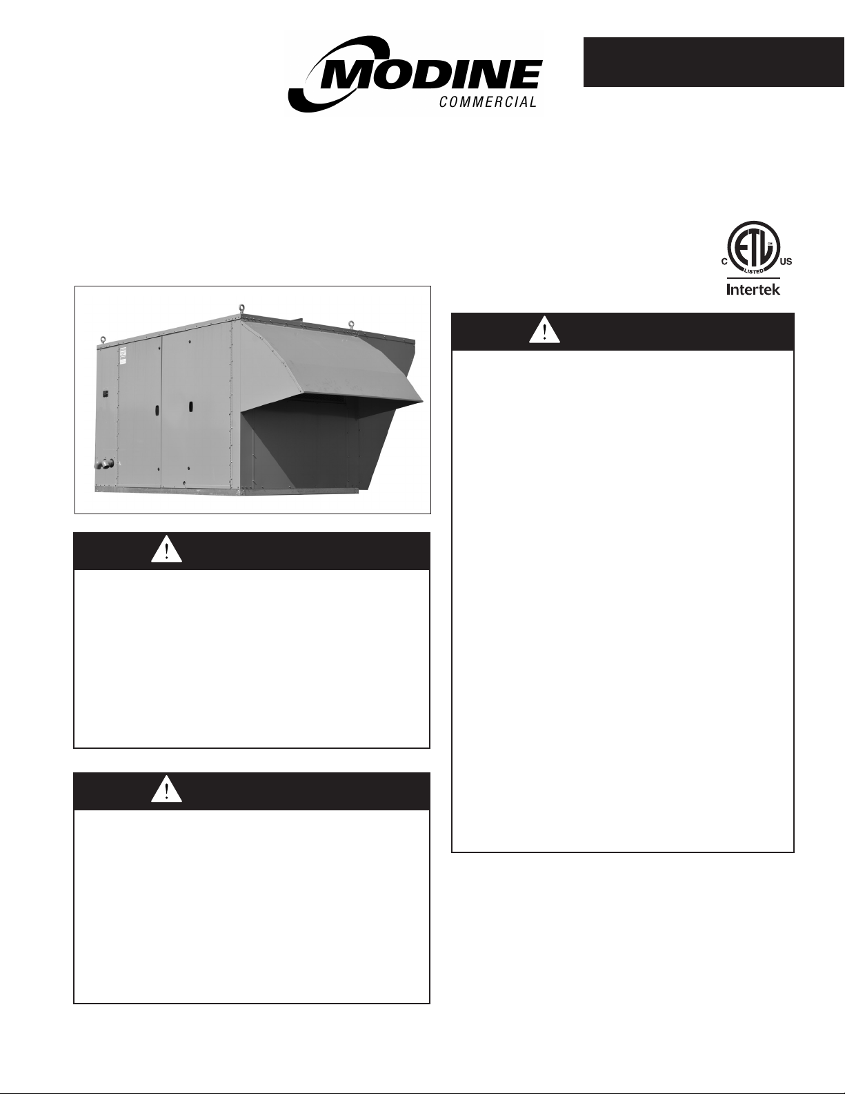
Model MPR Commercial Packaged Ventilation
System Unit (C-Cabinet size shown)
Improper installation, adjustment, alteration,
service or maintenance can cause property
damage, injury or death, and could cause
exposure to substances which have been
determined by various state agencies to cause
cancer, birth defects or other reproductive
harm. Read the installation, operating and
maintenance instructions thoroughly before
installing or servicing this equipment.
This unit contains R-410A high pressure
refrigerant. Hazards exist that could result in
personal injury or death. Installation,
maintenance, and service must only be
performed by an HVAC technician qualified in
R-410A refrigerant and using proper tools and
equipment. Due to much higher pressure of
R-410A refrigerant, DO NOT USE service
equipment or tools designed for refrigerants
other than R410A.
WARNING
WARNING
(for units with 24 digit model numbers)
FIRE OR EXPLOSION HAZARD
Failure to follow safety warnings exactly could
result in serious injury, death or property
damage.
Be sure to read and understand the installation,
operation and service instructions in this manual.
Improper installation, adjustment, alteration,
service or maintenance can cause serious
injury, death or property damage.
Do not store or use gasoline or other
flammable vapors and liquids in the vicinity
of this or any other appliance.
WHAT TO DO IF YOU SMELL GAS:
• Do not try to light any appliance.
• Do not touch any electrical switch, do
not use any phone in your building.
• Leave the building immediately.
• Immediately call your gas supplier from
a phone remote from the building.
Follow the gas supplier’s instructions.
• If you cannot reach your gas supplier,
call the fire department.
Installation and service must be performed by
a qualified installer, service agency or the gas
supplier.
Inspection on Arrival
1. Inspect unit upon arrival. In case of damage, report it
immediately to transportation company and your local
factory sales representative.
2.
Check rating plate on unit to verify that power supply meets
available electric power at the point of installation.
3. Inspect unit upon arrival for conformance with description
of product ordered (including specifications where
applicable).
WARNING
THIS MANUAL IS THE PROPERTY OF THE OWNER.
PLEASE BE SURE TO LEAVE IT WITH THE OWNER WHEN YOU LEAVE THE JOB.
1MCP15-500.7
SPECIAL PRECAUTIONS
SPECIAL PRECAUTIONS
THE INSTALLATION AND MAINTENANCE INSTRUCTIONS IN
THIS MANUAL MUST BE FOLLOWED TO PROVIDE SAFE,
EFFICIENT AND TROUBLE-FREE OPERATION. IN ADDITION,
PARTICULAR CARE MUST BE EXERCISED REGARDING
THE SPECIAL PRECAUTIONS LISTED BELOW. FAILURE
TO PROPERLY ADDRESS THESE CRITICAL AREAS COULD
RESULT IN PROPERTY DAMAGE OR LOSS, PERSONAL
INJURY, OR DEATH. THESE INSTRUCTIONS ARE SUBJECT
TO ANY MORE RESTRICTIVE LOCAL OR NATIONAL CODES.
HAZARD INTENSITY LEVELS
1. DANGER: Indicates an imminently hazardous situation
which, if not avoided, WILL result in death or serious injury.
2. WARNING: Indicates a potentially hazardous situation
which, if not avoided, COULD result in death or serious injury.
3. CAUTION: Indicates a potentially hazardous situation
which, if not avoided, MAY result in minor or moderate injury.
4. IMPORTANT: Indicates a situation which, if not avoided,
MAY result in a potential safety concern.
dANGeR
Appliances must not be installed where they may be exposed
to a potentially explosive or flammable atmosphere.
WARNING
de-energized.
11. This unit contains R-410A high pressure refrigerant.
Hazards exist that could result in personal injury or
death. Installation, maintenance, and service must only
be performed by an HVAC technician qualified in R-410A
refrigerant and using proper tools and equipment. Due
to much higher pressure of R-410A refrigerant, DO NOT
USE service equipment or tools designed for refrigerants
other than R410A.
12. The power supply wiring for the Energy Recovery
Section comes from a single point power connection on
the unit. Disconnect power supply at model MPR before
making wiring connections to prevent electrical shock
and equipment damage.
13. When servicing or repairing this equipment, use only
factory-approved service replacement parts. A complete
replacement parts list may be obtained by contacting
Modine Manufacturing Company. Refer to the rating
plate on the appliance for complete appliance model
number, serial number, and company address. Any
substitution of parts or controls not approved by the
factory will be at the owner's risk.
WARNING
1. Failure to follow proper lifting instructions could result in
property damage, serious injury, or death. Lifting should
only be done by a qualified rigging company. Use ALL
lifting points. Test lift to ensure proper balance and
rigging. Never lift in high winds.
2. Disconnect power supply before making wiring
connections or working on this equipment. Follow all
applicable safety procedures to prevent accidental
power up. Failure to do so can result in injury or death
from electrical shock or moving parts and may cause
equipment damage.
3. For units equipped for dual power supply sources, both
sources of power must be disconnected to prevent
electrical shock and equipment damage.
4. All appliances must be wired strictly in accordance with
the wiring diagram furnished with the appliance. Any
wiring different from the wiring diagram could result in a
hazard to persons and property.
5. Any original factory wiring that requires replacement
must be replaced with wiring material having a
temperature rating of at least 105°C.
6. Ensure that the supply voltage to the appliance, as
indicated on the serial plate, is not 5% greater than the
rated voltage.
7. All field gas piping must be pressure/leak tested prior to
operation. Never use an open flame. Use a soap solution or
equivalent for testing.
8. Gas pressure to appliance controls must never exceed
14" W.C. (1/2 psi).
9. To reduce the opportunity for condensation, the minimum
sea level gas input to the appliance, as indicated on the
serial plate, must not be less than 5% below the rated
input, or 5% below the minimum rated input of dual rated
units.
10. When the dead front disconnect switch(es) (for main
unit and/or powered convenience outlet option) is in the
“OFF” position, supply power remains energized at the
line (supply) side of the dead front disconnect switch(es).
The switch body is located inside of another junction
box to protect against contact with the live wiring.
The junction box must not be disassembled unless
the main power supply from the building to the unit is
CAUtIoN
1. Appliances are designed for outdoor installation only.
DO NOT LOCATE APPLIANCES INDOORS.
2. Ensure that the supply voltage to the appliance, as
indicated on the serial plate, is not 5% less than the
rated voltage.
3. Purging of air from gas lines should be performed as
described in ANSI Z223.1 - latest edition “National Fuel
Gas Code”, or in Canada in CAN/CGA-B149 codes.
4. Units not approved for use in potable water systems.
5. Do not operate the unit with steam. The coil is not
designed for steam condensate removal which can
damage the unit.
6. Hot water supplied to the hot water heating option must
not exceed 180°F temperature or 75 PSIG pressure.
7. When servicing the unit, some components may be hot
enough to cause pain or injury. Allow time for cooling of
hot components before servicing.
8. Do not overcharge the refrigeration system. This can
lead to elevated compressor discharge pressure and
possibly flooding the compressor with liquid. This may
result in compressor failure not covered under warranty.
9. Do not reuse any mechanical or electrical component
which has been wet. Such components must be
replaced.
IMPoRtANt
1. To prevent premature heat exchanger failure, do
not locate ANY gas-fired appliances in areas where
corrosive vapors (i.e. chlorinated, halogenated or acid)
are present in the atmosphere.
2. A properly designed drain with trap must be installed
immediately after the unit evaporator coil condensate
drain pan connection. Failure to do so will result in
condensate that cannot properly drain from the unit,
2 MCP15-500.7
TABLE OF CONTENTS / SI (METRIC) CONVERSION FACTORS / UNIT LOCATION
TABLE OF CONTENTS
IMPoRtANt
eventually causing the drain pan to fill. To prevent
damage to the building or unit, a drain pan float switch
is included as standard and will disable the unit if the
maximum condensate level is reached.
3. To prevent premature heat exchanger failure, the input
to the appliance, as indicated on the serial plate, must
not exceed the rated input by more than 5%.
4. To prevent premature heat exchanger failure, check to
be sure the blower has been set to deliver the proper
airflow for the application. Refer to page 17 for Blower
Adjustments.
5. Start-up and adjustment procedures must be performed
by a qualified service agency.
6. All scroll compressors requires the correct supply power
phase rotation. Phase reversal may result in compressor
failure not covered under warranty. Refer to the Start-Up
Procedure section.
7. All refrigeration checks must be made by a qualified
R-410A refrigeration technician.
8. Do not release refrigerant to the atmosphere. When
adding or removing refrigerant, all national, state/
province, and local laws must be followed.
9. On units with the electric preheat option, to prevent
premature heat exchanger failure, check to be sure the
blower has been set to deliver the proper airflow for the
application. Refer to page 17 for Blower Adjustments.
10. The exhaust fan is not designed for high temperature
or smoke control exhaust applications. Exhaust air
temperature must not exceed 104°F. Operating the
exhaust fan above 104°F will result in failure of the
exhaust fan.
SI (METRIC) CONVERSION FACTORS
To Convert Multiply By To Obtain
"W.C. 0.24 kPa
psig 6.893 kPa
°F (°F-32) x 0.555 °C
inches 25.4 mm
feet 0.305 meters
CFM 0.028 m
3
Special Design Requests
Modine Manufacturing Company will sometimes build units
with special features as requested by the customer. This
manual only covers standard features and does not include any
changes made for special feature requests by the customer.
Units built with special features are noted with an SPO (Special
Product Order) Number on the Serial Plate
To Convert Multiply By To Obtain
CFH 1.699 m
3
0.0374 mJ/m
Btu/ft
pound 0.453 kg
Btu/hr 0.000293 kW
gallons 3.785 liters
psig 27.7 "W.C.
/min
3
/min
3
Inspection on Arrival ............................................................ 1
Special Precautions ............................................................. 2
SI (Metric) Conversion Factors ........................................... 3
Special Design Requests .................................................... 3
Storage Prior to Installation ................................................. 3
Unit Location ....................................................................... 4
Installation ......................................................................4-15
Combustible Material and Service Clearances .........4-5
Roof Curb Installation ................................................... 4
General Rigging Instructions/Unit Installation ...........6-7
Duct & Condensate Drain Installation .......................... 8
Electrical Connections .................................................. 9
Gas Connections ........................................................ 10
Vent Terminals and Combustion Air Hoods ................ 11
Gas Heating Option Condensate Drains & Traps ......14
Hot Water Piping Connections ...................................15
Start-Up Procedure ......................................................16-29
General. ...................................................................... 16
Blower Adjustments .................................................... 17
Airflow Proving Switch and Dirty Filter Switch............ 19
Variable Air Movement Applications ........................... 19
Checking Refrigerant Charge ..................................... 20
Gas Heating Option .................................................... 21
Energy Recovery Option (B-Cabinet units only) ........ 28
Unit Features/Options Location Drawings .................... 30-35
Dimensions/Weights .................................................... 36-44
B-Cabinet Size Unit without Energy Recovery. .......... 36
B-Cabinet Size Unit with Energy Recovery. ............... 38
C-Cabinet Size Unit .................................................... 40
D-Cabinet Size Unit .................................................... 42
Base Model Weights ...................................................44
Option and Accessory Pressure Drop Tables ..............45-47
Maintenance .................................................................48-50
Service & Troubleshooting ...........................................51-55
Serial Plates ...................................................................... 56
Model Nomenclature ....................................................57-59
Commercial Warranty ...........................................Back Page
Storage Prior to Installation
If the unit is stored outside prior to installation, the unit should
be covered.
3MCP15-500.7
*Available as a factory
supplied, field installed
accessory.
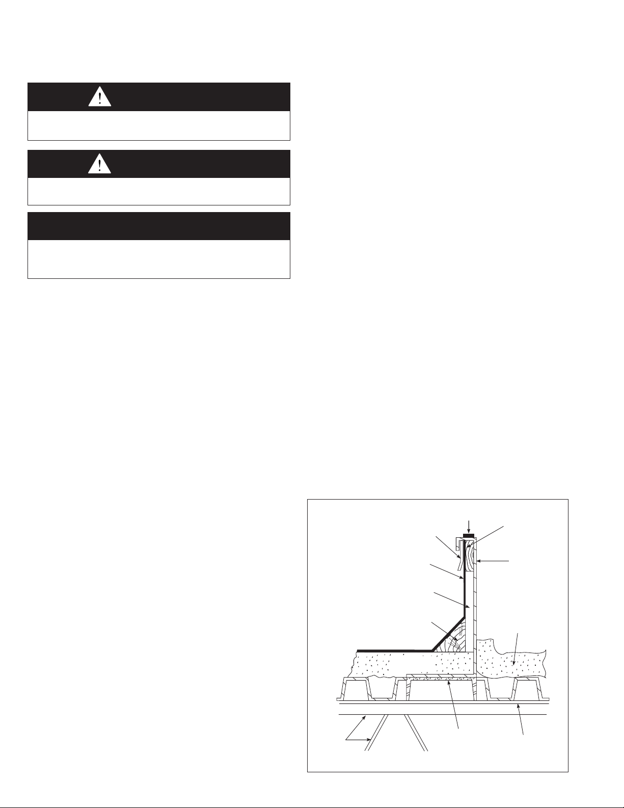
Curb Gasketing*
2 x 4 Wooden
Nailing Strip*
Curb*
2” Acoustic
Fiberglass
(By Others)
Roof Deck
6” Inverted Channel
(Both Sides)
(By Others)
Roof
Trusses
Cant Strip
(By Others)
Roof Insulation
(By Others)
Counterflashing
(By Others)
Roofing Material
(By Others)
Insulation
(By Others)
UNIT LOCATION
dANGeR
Appliances must not be installed where they may be
exposed to potentially explosive or flammable atmosphere.
CAUtIoN
Appliances are designed for outdoor installation only.
DO NOT LOCATE APPLIANCES INDOORS.
IMPoRtANt
To prevent premature heat exchanger failure, do not locate
ANY gas-fired appliances in areas where corrosive vapors (i.e.
chlorinated, halogenated or acid) are present in the atmosphere.
Location Recommendations
1. When locating the packaged rooftop unit, Model MPR,
consider general space and cooling/heating requirements and
availability of gas and electrical supply.
2. Be sure the structural support at the unit location site is
adequate to support the weight of the unit and any other
required support structure. For proper operation the unit
must be installed in a level horizontal position.
3. All mechanical equipment generates some sound and
vibration that may require attenuation. Locating the
equipment away from the critical area is desirable within
ducting limitations. Frequently, units can be located above
utility areas, corridors, restrooms, and other non-critical
areas. Generally, a unit should be located within 15 feet of
a primary support beam. Smaller deflections mean lesser
vibration and noise transmission. For critical applications,
please consult with an acoustical attenuation expert.
4. Do not install units in locations where the flue products
(if equipped with a gas fired heating option) can be drawn
into the adjacent building openings such as windows, fresh
air intakes, etc.
5. Be sure that the minimum clearances to combustible
materials and recommended service clearances are
maintained. For units with the gas heating option, be sure
clearances are maintained to the combustion air inlet
louvers and power exhauster discharge cover. Units are
designed for installation on non-combustible surfaces with
the minimum clearances shown in Figure 5.1.
6. On units that have fresh air openings, a method must be
provided to prevent water and debris from entering the unit
such as a rainhood, which is available as an accessory
from Modine. Where possible, install the unit so that the
inlet is not facing into the prevailing wind to prevent water
entrainment.
7. The exhaust fan is not designed for high temperature
or smoke control exhaust applications. Exhaust air
temperature must not exceed 104°F. Operating the
exhaust fan above 104°F will result in failure of the
exhaust fan.
Roof Curb Installation
An optional roof curb is available to simplify site preparation
and raise the unit above roof water and snow level for
drainage. It can be installed in advance of the unit. The curb
is shipped knocked down with separate instructions (Literature
#MCP15-590) for its assembly, flashing, and sealing with the
roof. The following are some general guidelines for roof curb
installed units:
1. The roof structure must be adequately designed to support
the live weight load of the unit and any other required
support structure. The roof curb should be supported at
points no greater than five feet apart. Additional truss
reinforcement should be provided, if necessary.
2. Roof curbs supplied by Modine are fabricated from 10
gauge galvanized steel and supplied knocked down for
assembly on the job site. The curb consists of two side
pieces, two end pieces, gasketing, four joiner angles, four
2x4 inch wood nailing strips, nuts, bolts, and washers.
3. Outside dimensions must be held when installing curb.
Top surface must be level and straight to ensure weathertightness. If roof is pitched it will be necessary to construct
a sub-base on which to install the curb. All corners must
be square.
4. All dimensions are +1/8 inch.
5. When a roof curb is used in conjunction with factory
supplied discharge and/or return air connectors, the
ductwork can be fastened to the connectors prior to the
unit installation. The connectors will accept 90° flanged
ductwork (see Figure 7.1).
6. Final electric and gas connections must be made after unit
is installed to allow for tolerance in setting of unit on curb.
For electrical power supply allow approximately eight feet
of wire, plus provisions for weathertight flexible conduit for
connection to unit, as required by local codes.
7. Maintain a 12-inch minimum height from top of roof deck
to top of curb.
8. Caulk butt joints after curb is assembled and installed on
roof structural members and roof flashing is added.
9. For improved sound attentuation, line the roof deck within
the curb area with 2" acoustic fiberglass.
Figure 4.1 - Typical Curb Details
4 MCP15-500.7
CLEARANCES / ROOF CURB INSTALLATION
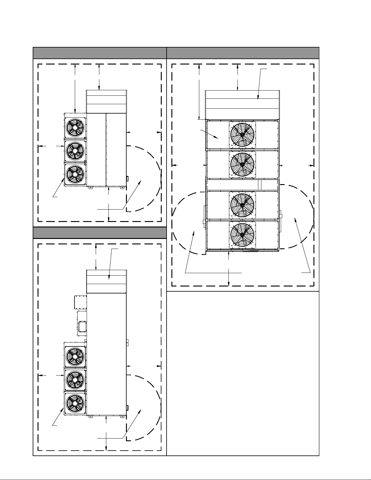
Figure 5.1 - Combustible Material & Service Clearances
B- AND C-CABINET UNITSWITHOUT ENERGY RECOVERY D-CABINET UNITSWITHOUT ENERGY RECOVERY
FIELD INSTALLED
SEE NOTE 2
36.0
SEE NOTE 2
36.0
ACCESSORY
RAINHOOD
48.0
SEE NOTE 3
36.0
SEE NOTE 4
FOR UNITS WITH GAS HEAT,
MAINTAIN 48" MINIMUM
FROM VENT TERMINATIONS
48.0
SEE NOTE 1
B- AND C-CABINET UNITSWITH ENERGY RECOVERY
FIELD INSTALLED
36.00
36.0
SEE NOTE 4
FOR UNITS WITH GAS HEAT,
MAINTAIN 48" MINIMUM
FROM VENT TERMINATIONS
48.0
SEE NOTE 1
ACCESSORY
RAINHOOD
48.0
SEE NOTE 3
SEE NOTE 4
48.00
SEE NOTE 3
48.00
SEE NOTE 1
FOR UNITS WITH GAS HEAT,
MAINTAIN 48" MINIMUM
FROM VENT TERMINATIONS
j The minimum recommended clearance for service is 48". For service
clearances less than shown, applicable local code requirements must be
followed. If the ability for future condenser coil replacement is desired, the
minimum clearance must be:
• 102" for B-Cabinet sized units
• 112" for C-Cabinet sized units
• 100” for D-Cabinet sized units
See Note k for alternate coil replacement direction.
k The minimum recommended clearance for service is 36". For service
clearances less than shown, applicable local code requirements must be
followed. If the ability for future condenser coil replacement is desired, the
minimum clearance must be (from the end panel of the condenser, not the
end of the inlet hood):
• 102” for B-Cabinet sized units
• 112” for C-Cabinet sized units
• 100” for D-Cabinet sized units
See Note j for alternate coil replacement direction.
l The minimum recommended clearance for service is 48". For service
clearances less than shown, applicable local code requirements must be
followed. If the ability for future evaporator coil, hot gas reheat coil, and/or
energy wheel replacement is desired, the minimum clearance must be:
• 55" for B-Cabinet sized units
• 64" for C-Cabinet sized units
• 100” for D-Cabint sized units
m Additional Required Clearances:
-Clearance above unit must be unobstructed.
-Clearance to combustibles below the unit is 6" minimum.
48.00
SEE NOTE 3
5MCP15-500.7
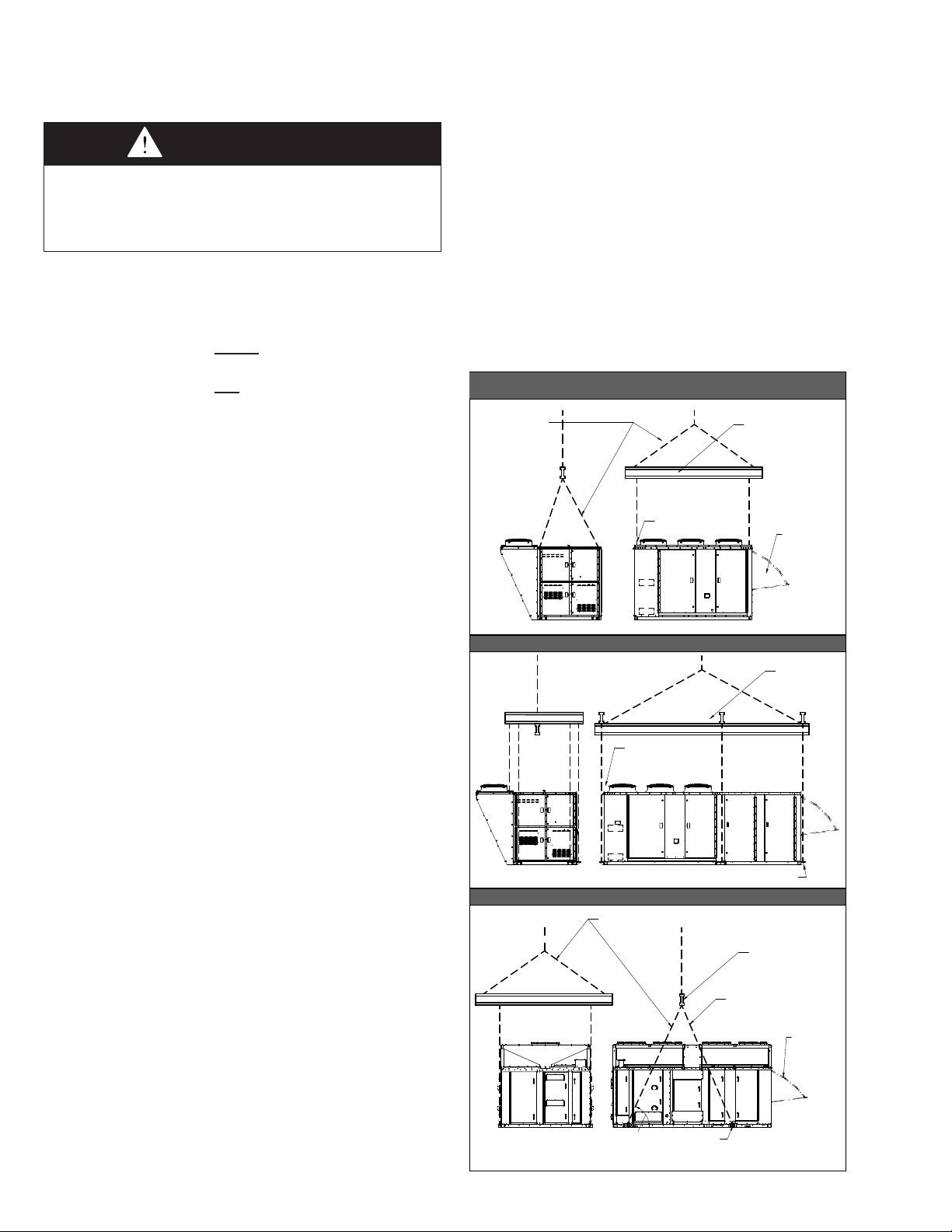
GENERAL RIGGING INSTRUCTIONS / UNIT INSTALLATION
SPREADER BAR
AND LIFTING
CHAINS/STRAPS
BY INSTALLER
ADJUST CHAIN/STRAP
LENGTH SO UNIT IS
LEVEL WHEN LIFTED
RAINHOOD
ACCESSORY
(FIELD INSTALL)
(4) 1.50" LIFTING EYE BOLTS
(EACH CORNER OF UNIT)
SPREADER BAR
AND LIFTING
CHAINS/STRAPS
BY INSTALLER
ENSURE THE LIFTING
CHAINS/STRAPS CLEAR
THE CASING ON EACH SIDE
(6) 1.0" LIFTING LUGS
MIN. 65
v
SPREADER BAR
AND LIFTING
CHAINS/STRAPS
BY INSTALLER
ADJUST CHAIN/STRAP
LENGTH SO UNIT IS
LEVEL WHEN LIFTED
RAINHOOD
ACCESSORY
(FIELD INSTALL)
ENSURE THE LIFTING
CHAINS/STRAPS CLEAR
THE CASING ON EACH SIDE
(4) 1.0" LIFTING LUGS
LIFTING LUG KIT IS SHIPPED LOOSE IN SUPPLY FAN SECTION.
INSTALL (4) LIFTING LUGS PER MCP15-505 USING (4) GRADE 5 BOLTS PER LUG, TORQUED TO 75 ft-lb.
B-CABINET UNIT - NO ENERGY RECOVERY
C-CABINET UNIT - ALL
D-CABINET UNIT - ALL
B-CABINET UNIT - WITH ENERGY RECOVERY
General Rigging Instructions
WARNING
Failure to follow proper lifting instructions could result in
property damage, serious injury, or death. Lifting should
only be done by a qualified rigging company. Use ALL lifting
points. Test lift to ensure proper balance and rigging. Never
lift in high winds.
Lifting Lug Installation
Before attaching lifting equipment, verify location of lifting lugs
or eyes. B- and C-Cabinet sized units have the lifting lugs or
eyes factory installed as follows:
• B-Cabinet sized units without Energy Recovery include
(4) eye bolts at each corner on the top of the unit.
• B-Cabinet sized units with Energy Recovery include (6)
lifting lugs on the base, one at each corner and one on
each length-wise side of the unit between the corners.
• C-Cabinet sized units include (4) eye bolts at each corner
on the top of the unit. For units that include the shipped
separate Energy Recovery Module (model ERM) option,
refer to the latest revision of the Installation and Service
Manual, #MCP15-520, that shipped with the ERM for
separate rigging instructions.
• D-Cabinet sized units must have the lifting lugs installed in
the unit base assembly prior to rigging as follows:
1. Locate the lifting lug kit box, kit # 66802, located in
the supply fan compartment.
2. Install the kit per the “Installation Instructions, Lifting
Lugs D-Cabinet”, #MCP15-505, included with the kit.
3. After installing the kit, verify that all (4) lugs are
installed following the instructions in Step 2. Verify
that each lug is secured using (4) Grade 5 bolts
provided with the kit. Each bolt must be torqued to
75 ft-lb.
Unit Rigging and Lifting
Rigging and lifting of the units should only be done by a
qualified rigging company. With the lifting lugs or eyes
identified and installed, the units can be lifted by crane or
helicopter.
1. Follow site preparation instructions for the roof curb or
equipment stand before installation.
2. Check the Serial Plate(s) of unit with plans to be sure unit
is properly located. Although units may look outwardly
similar, their function, capacities, options, and accessories
will often vary.
3. Check unit dimensions of both the unit base and the curb
or stand on which the unit will be installed.
4. If the unit will be installed on a roof curb:
a. Thoroughly clean and dry the top of the curb surface.
b. Lay a bead of weather resistant caulking on top
perimeter of roof curb as illustrated in Figure 7.1. Note:
If roof curb is supplied by Modine, full perimeter gasket
material is supplied and caulking is not necessary.
5. When lifting the equipment, connect sturdy steel cables,
chains, or straps with eye loops as illustrated in Figure 6.1.
For stability in lifting and lowering and to prevent damage
to the unit, include a spreader bar as illustrated in Figure
6.1. Avoid twisting or uneven lifting of the unit. The cable
length from the lifting point on the unit to the spreader bar
should always be longer than the distance between the
outer lifting points.
6. Test lift the unit to check for proper rigging balance before
hoisting to the desired installation location.
7. Once lifted to the installation location, orient the hoisted
unit to match the ductwork locations and set evenly on the
curb or stand.
8. Following the instructions in this manual, make final unit
connections to the electric power supply and remote
control circuits. Connect the gas lines to the unit heating
compartment. Seal all utility line clearance holes on the unit
after connections are completed so they are watertight.
Figure 6.1 - Typical Rigging for Model MPR
6 MCP15-500.7
DUCT INSTALLATION AND UTILITY CONNECTIONS
RETURN AIR
CONNECTOR
DISCHARGE AIR
CONNECTOR
90° FLANGED
DUCTWORK
(By Installer)
UNIT BASE
(Shown without
unit for clarity)
ROOF
CURB
BEFORE UNIT
INSTALLATION
CAULK ALL MATING
SURFACES ➀
(Caulk by installer)
➀ If roof curb is supplied
by Modine, full perimeter
gasket material is supplied
and caulking is not necessary.
Duct Installation
1. The unit is designed to accept 90° flanged ductwork on both
the supply and return air openings. Refer to the roof curb or
the unit base dimensional drawings to determine the location
of the openings.
2. Acoustic duct liners are recommended on all internal supply
and return air ducts.
3. When ductwork is installed prior to unit arrival, flexible
connections should be included to make connections easier
and to simplify possible future service.
4. When a roof curb is used in conjunction with factory supplied
discharge and/or return air connectors, the ductwork can be
fastened to the connectors prior to the unit installation. The
connectors will accept 90° flanged ductwork (see Figure 7.1).
Figure 7.1 - Discharge and/or Return Air Connectors
5. To assure proper air flow from the unit, follow these duct
design recommendations:
a. Be sure ducts are properly sized and installed.
b. As a general rule, all discharge ducts should have a
A = Cross Sectional Area of Rectangular Duct
P = Perimeter of Rectangular Duct
D = Diameter of Round Cut
c. Wherever turns in the duct work are made, include
d. Supply air ducts in a “T” configuration should be
avoided to prevent air temperature stratification. If this
configuration must be used, provide appropriate mixing
devices and/or the necessary straight duct length before
the “T” to provide uniformly mixed air temperature
delivery to both supply air duct trunks.
Utility Connections
Utility and control connections can be made to the unit from
the bottom or through the fixed side panels. Holes can be field
drilled in fixed side panels to accommodate utility connections
as shown on the unit dimensional drawings and the utility
entrance location area label located on the unit. All gas and
electrical connections to the unit must be weatherized so they
are watertight.
straight run of at least three (3) hydraulic duct diameters
before making turns in the ductwork.
Hydraulic Duct Diameter for Rectangular Ducts = 4A/P
Hydraulic Duct Diameter for Circular Ducts = D
where:
turning vanes.
7MCP15-500.7
CONDENSATE DRAIN INSTALLATION
Evap Condensate Drain Trap Installation
IMPoRtANt
A properly designed drain with trap must be installed
immediately after the unit evaporator coil condensate drain
pan connection. Failure to do so will result in condensate
that cannot properly drain from the unit, eventually causing
the drain pan to fill. To prevent damage to the building or
unit, a drain pan float switch is included as standard and will
disable the unit if the maximum condensate level is reached.
All units require a drain system with a condensate trap to be
connected to the condensate drain pan connection which is
accessible from the exterior of the unit casing. Failure to install
a condensate drain trap may result in condensate overflowing
from the drain pan, causing damage to the unit and building.
See Figure 30.1 or 31.1 for location. The drain system is to be
installed as follows:
1. The condensate drain pan includes a 1-1/4" female NPT
stainless steel connection accessible from the exterior of the
unit casing. Do not reduce the drain diameter. A drain pan
connection kit is shipped loose for field installation to allow
connection exterior to the casing. Refer to Figure 8.1 for
assembly details.
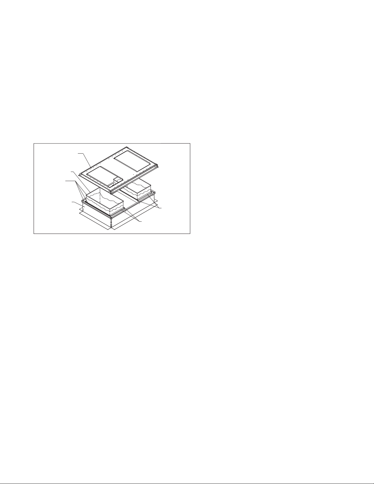
Figure 8.1 - Condensate Drain Pan Connection Kit
Threaded Connection on
Evap Coil Drain Pan
Threaded Nipple
Note: All kit components shown
are factory supplied for field installation.
Rubber Washer
Corrosion Resistant
Steel Washer
Corrosion Resistant
Steel Locknut
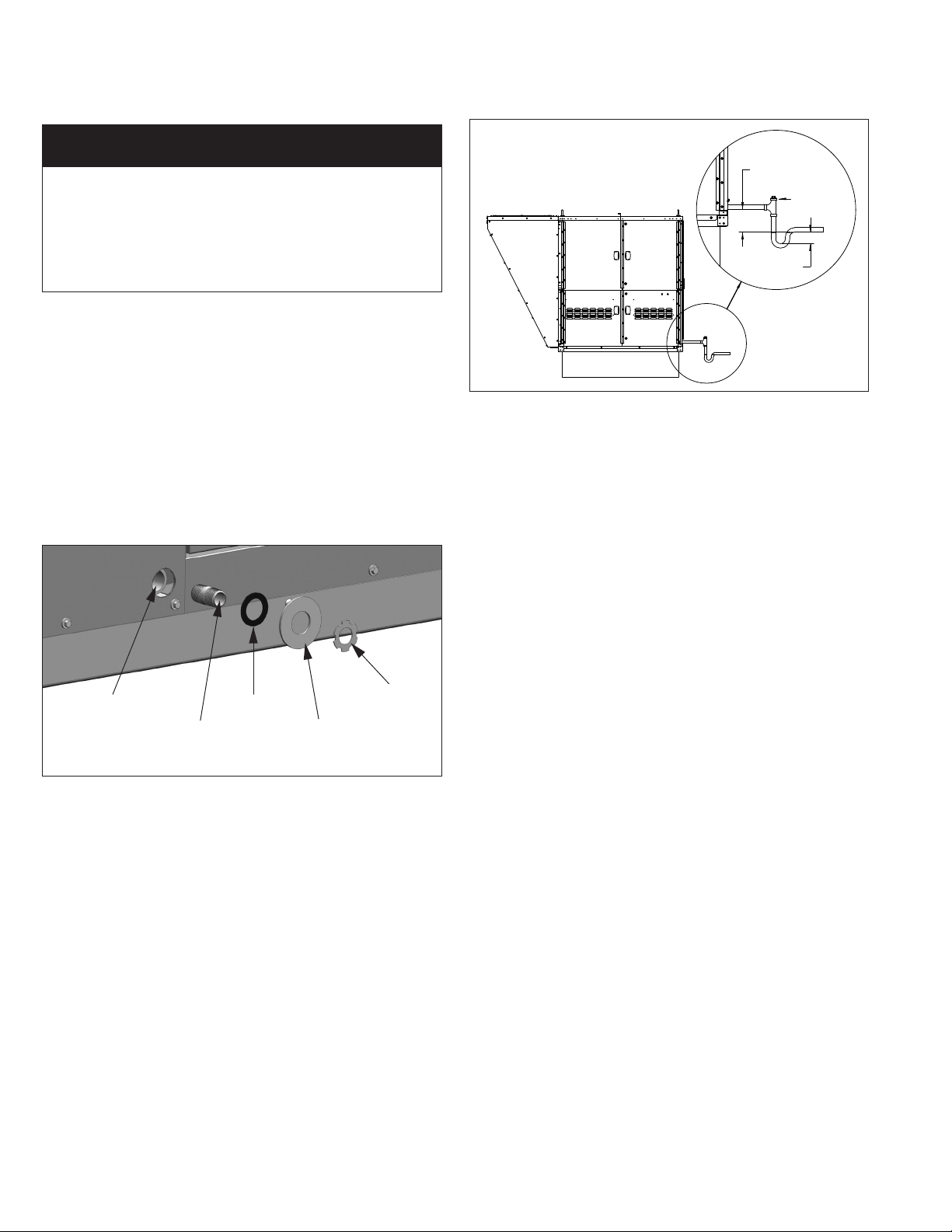
Figure 8.2 - Condensate Drain Trap Installation
Note: All piping components
shown are supplied by others.
•Thetrapdepthmustbe½xthetrapheight.Forexample,if
the trap height is the minimum 6”, the trap depth must be 3”
(see Figure 8.2).
•Formaintenance,itisrecommendedtohaveacapped
cleanout at the top of the trap as shown in Figure 8.2.
5. After the exit from the trap, the drain must be pitched
down from the unit connection at least 1” for every 10 feet
of horizontal run to promote proper drainage. If the local
installation code allows, the drain can be run to a waste
water system.
6. If the trap may experience below freezing temperatures
during non-cooling periods, heating wraps must be used to
avoid water from freezing in and damaging the trap and drain
system.
7. The trap must be primed before the unit is put into operation
and properly maintained on a regular schedule. Refer to the
Start-Up Procedure section and the Maintenance section for
additional guidance.
TRAP HEIGHT
(6" MINIMUM)
CAPPED
CLEANOUT
1/2 x TRAP
HEIGHT
2. The drain line should include provisions for disconnecting the
line at or near the unit for maintenance/servicing of the unit.
The drain line must not interfere with access panels, which
are removable for maintenance/service.
3. The drain line must include a trap immediately after the
unit, as shown in Figure 8.2. Failure to do so will result
in condensate that cannot properly drain from the unit,
eventually causing the drain pan to fill and overflow. If the
drain pan overflows, significant damage can occur to the unit
and/or building on which the unit is installed. A drain pan float
switch is included as standard and will disable the unit if the
maximum condensate level is reached.
4. The design of the trap is critical to ensure proper drainage.
If the trap is not constructed properly with the dimensions
as outlined in the following instructions, air could be drawn
through the drain pipe and into the system or could back up
into the drain pan.
•Thedrainislocatedonthesuctionsideofthemain
supply air fan, resulting in a negative pressure relative to
outside the unit cabinet. The trap height must be at least
6” to account for maximum negative pressure, including
allowance for dirty filters. Note that the trap height is the
difference in height from the drain connection of the unit to
the leaving side of the trap. Refer to Figure 8.2.
8 MCP15-500.7
ELECTRICAL CONNECTIONS
Electrical Connections
WARNING
1. Disconnect power supply before making wiring
connections or working on this equipment. Follow all
applicable safety procedures to prevent accidental
power up. Failure to do so can result in injury or death
from electrical shock or moving parts and may cause
equipment damage.
2. For units equipped for dual power supply sources, both
sources of power must be disconnected to prevent
electrical shock and equipment damage.
3. All appliances must be wired strictly in accordance with
the wiring diagram furnished with the appliance. Any
wiring different from the wiring diagram could result in a
hazard to persons and property.
4. Any original factory wiring that requires replacement
must be replaced with wiring material having a
temperature rating of at least 105°C.
5. Ensure that the supply voltage to the appliance, as
indicated on the serial plate, is not 5% greater than
rated voltage.
roltage.
CAUtIoN
Ensure that the supply voltage to the appliance, as indicated
on the serial plate, is not 5% less than the rated voltage.
1. Installation of wiring must conform with local building
codes, or in the absence of local codes, with the National
Electric Code ANSI/NFPA 70 - Latest Edition. Unit must be
electrically grounded in conformance to this code. In
Canada, wiring must comply with CSA C22.1, Part 1,
Electrical Code.
2. Two copies of the job specific wiring diagram are provided
with each unit, one permanently affixed to the inside of the
door of the controls compartment and the other as a loose
copy with the literature packet that ships with the unit.
Refer to this diagram for all wiring connections.
3. Control wiring consists of both 24V analog control wiring
and low current digital control signal wiring. To avoid signal
interference, the two types should be run in separate
conduits. If run in the same conduit, the digital signal wiring
should be shielded at one end of the wiring run. Wiring
should be twisted, stranded, and shielded communication
wire.
4. The wire gauge must be sized according to the National
Electric Code or CSA code based on amp draw and length
of run. Refer to Table 9.1 for maximum wire lengths and
the number of wires that can be wired to each low voltage
terminal block based on the wire gauge being used.
Table 9.1 - 24V and Digital Control Wire Lengths
Minimum
Recommended
Wire Gauge
22 n/a 120
20 n/a 200
18 75 300
16 125 500
14 175 n/a
24V Control Wiring Digital Control Wiring
Maximum Distance from
Control Device to Unit
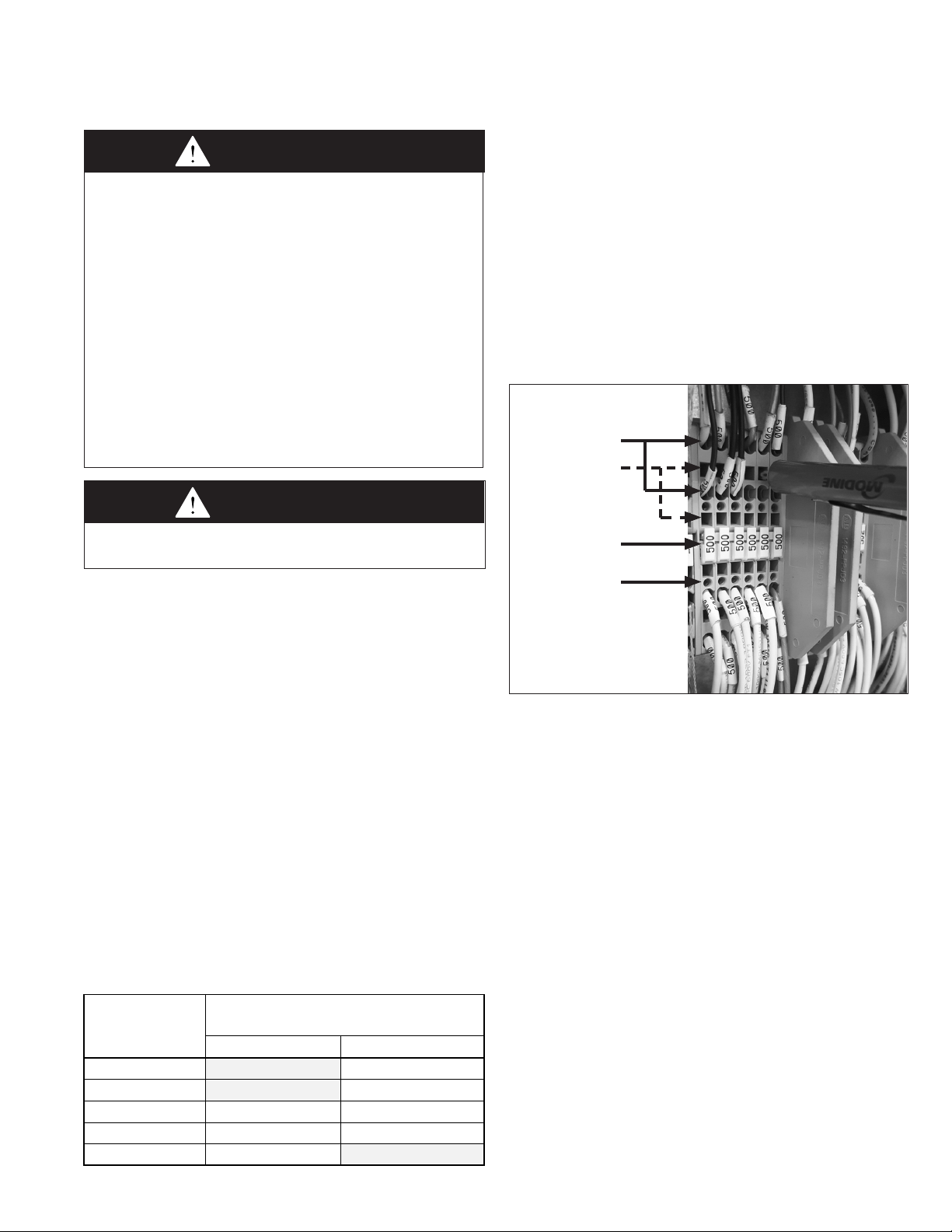
5. For field wiring to the factory terminal strip, the terminal
strip connections are designed to clamp down on the wires.
To properly connect the wires to the terminal strip:
• Push a small flat-head screwdriver into the square hole on
the terminal. Press firmly until the screwdriver hits the
back stop and opens the terminal (see Figure 9.1).
• Remove approximately 3/8” of insulation from the end of
the wire and push the stripped wire into the oval hole in
the terminal.
• Remove the screwdriver. Pull on the wire to make sure
that it is securely clamped in the terminal.
• Make sure that the terminal clamp is in contact with bare
wire (insulation removed).
Figure 9.1 - Terminal Strip Wiring
Oval Holes
for Wiring
(two rows each)
Square Holes
for Wire Release
(two rows each)
Terminal
Numbers
Test Probe
Points
6. Depending on the configuration of the unit controls, there
may be sensors that are field installed. Review the unit
ordered to verify that the sensors supplied match the
configuration of the unit. The following are sensors that
may be included for field installation:
• Supply Air Temperature Sensor
This sensor is required on all units and should be
mounted in the supply air ductwork downstream of the
unit. The sensor should be located at least 5 feet, but not
more than 20 feet downstream from the unit discharge.
• Space Temperature/Humidity Sensor
This sensor is required on all units that have space
temperature/humidity reset control. The sensor is to be
wall-mounted in the space at a height of approximately
5 feet from the floor.
• Building Pressure Sensor
This sensor is required on all units that have space
pressure control, either through modulating dampers or
variable frequency drive control on the supply air blower.
The sensor is to be mounted inside a control panel in the
space and includes two pressure taps. One pressure tap
is for outside atmospheric pressure reference, the other is
for sampling the space pressure.
• Duct Pressure Sensor
This sensor is required on all units that have duct
pressure control through variable frequency drive control
on the supply air blower. The sensor is to be mounted
with the sensing probe inserted into the supply duct. The
atmospheric pressure sampling tap is left open.
9MCP15-500.7
ELECTRICAL CONNECTIONS / GAS CONNECTIONS
• Space CO2 Sensor
This sensor is required on all units that have demand
based ventilation control. The sensor is to be mounted in
the space at a height of approximately 5 feet from the
floor.
• Duct Mounted Smoke Detector
When ordered as a field installed accessory, the detector
should be mounted in the supply air or return air ductwork.
For further instructions on the above sensor(s), refer to
the installation instructions that shipped with the
sensor(s).
7. If the unit is a C-Cabinet sized unit with a Modine supplied
Energy Recovery Module, Model ERM, the wiring
connection between the MPR unit and the ERM unit must
be made by extending the loose end of the wire drop
located in the MPR unit outside air damper section, through
the transition duct between units, and connected to the
ERM control panel. Refer to the Installation & Service
Manual that shipped with the ERM (Literature #MCP15-
520) for additional instructions. If the unit is a B-Cabinet
sized unit with integral Energy Recovery, the unit is already
factory wired to the Energy Recovery section.
8. The power supply to the unit must be protected with a
fused or circuit breaker disconnect switch. Refer to the
Figures on pages 32 through 35 for the location of the
factory installed dead front disconnect option, if provided.
Field installed disconnect switches should be mounted
where required by the National Electric Code. Refer to the
Model Serial plate for MCA and MOP values for the unit.
9. The power supply must be within +/-5% percent of the
voltage rating and each phase must be balanced within 2
percent of each other. If not, advise the utility company.
10. External electrical service connections that must be
installed include:
a. Supply power (120, 208, 240, 480, or 600 volts).
b. Thermostats, building pressure sensors, or any other
accessory control devices that may be supplied (24
volts).
11. All outdoor electrical connections must be weatherized to
prevent moisture from entering the electrical compartment.
12. Electrical connections are made in the controls cabinet and
can be run through the bottom or side of the unit. Refer to
the unit and base dimensional drawings for locations of
wiring entrance. Refer to the wiring diagram for the terminal
location of all low voltage wiring.
REVIEW BEFORE PROCEEDING
THIS SECTION APPLIES TO UNITS WITH
(MODEL DIGIT 17=2 OR 3).
IF THE UNIT DOES NOT HAVE GAS HEAT,
Gas Connections
WARNING
1. All field gas piping must be pressure/leak tested prior
to operation. Never use an open flame. Use a soap
solution or equivalent for testing.
2. Gas pressure to appliance controls must never
exceed 14" W.C. (1/2 psi).
3. To reduce the opportunity for condensation, the
minimum sea level gas input to the appliance, as
indicated on the serial plate, must not be less than
5% below the rated input, or 5% below the minimum
rated input of dual rated units.
CAUtIoN
Purging of air from gas supply line should be performed as
described in ANSI Z223.1 - latest edition “National Fuel Gas
Code”, or in Canada in CAN/CGA-B149 codes.
IMPoRtANt
To prevent premature heat exchanger failure, the input to the
appliance, as indicated on the serial plate, must not exceed
the rated input by more than 5%.
1. Installation of piping must conform with local building codes,
or in the absence of local codes, with the National Fuel Gas
Code, ANSI Z223.1 (NFPA 54) - Latest Edition. In Canada,
installation must be in accordance with CAN/CGA-B149.1 for
natural gas units and CAN/CGA-B149.2 for propane units.
2. Piping to units should conform with local and national
requirements for type and volume of gas handled, and
pressure drop allowed in the line. Refer to Table 11.1 to
determine the cubic feet per hour (cfh) for the size of unit
to be installed. Using this cfh value and the length of pipe
necessary, determine the pipe diameter from Table 11.2.
Where several units are served by the same main, the total
capacity, cfh and length of main must be considered. While
the gas connection(s) on the unit may be smaller than 1", do
not use pipe sizes smaller than 1" leading up to the unit. At
the unit, reduce the pipe size down to the appropriate size
(refer to Table 11.1 for connection sizes). Table 11.2 allows
for a 0.3" W.C. pressure drop in the supply pressure from the
building main to the unit. The inlet pressure to the unit must
be 6-7" W.C. for natural gas and should not drop below 6.0"
W.C. when the unit is operating. When sizing the inlet gas
pipe diameter, make sure that the unit supply pressure can
be met after the 0.3" W.C. has been subtracted. If the 0.3"
W.C. pressure drop is too high, refer to the Gas Engineer’s
Handbook for other gas pipe capacities.
OPTIONAL GAS HEAT
SKIP TO PAGE 15.
roltage.
10 MCP15-500.7
GAS
GAS CONNECTIONS
Furnace Size
(Btu/hr)
Gas Consumption
(CFH)
Gas
Connection
Table 11.1 - Natural Gas Heating Gas Consumption
Digit 6 Digit 18
F 150,000 143 1/2"
G 200,000 190 3/4"
H 250,000 238 3/4"
B
J 300,000 286 3/4"
K 400,000 381 3/4"
R 175,000 167 1/2"
S 225,000 214 3/4"
T 310,000 295 3/4"
J 300,000 286 3/4"
K 400,000 381 1"
C
L 500,000 476 1"
L 600,000 571 1"
U 350,000 333 1"
V 450,000 429 1"
K 400,000 381 1.5" x 2
L 500,000 476 1.5" x 2
M 600,000 571 1.5" x 2
Q 800,000 762 1.5" x 2
D
1 900,000 857 1.5" x 2
2 1,000,000 952 1.5" x 2
3 1,200,000 1143 1.5" x 2
4 1,400,000 1333 1.5" x 2
5 1,600,000 1524 1.5" x 2
j Natural gas consumption based on a heating value of 1050 Btu/cu. ft.
k C-Cabinet units consist of two furnaces that together total the value shown in
Table 11.1.
l D-Cabinet units consist of two furnaces that together total the value shown
in Table 11.1 for sizes up to 800,000 Btu/hr. For sizes over 800,000 Btu/hr,
the unit consists of four furnaces that together total the value shown in Table
11.1.
3. The gas piping to the unit can enter the unit from the side
of the unit (refer to the unit dimensions) or from below (refer
to the base dimensions). A drill locator sticker and dimple is
located on the side of the unit to indicate the safe area for
drilling the hole for side gas pipe entry on B- and C-Cabinet
sized units. D-Cabinet sized units include a holes with
grommets for side pipe entry. Install a ground joint union
with brass seat and a manual shut-off valve external of the
unit casing, and adjacent to the unit for emergency shut-off
and easy servicing of controls, including a 1/8" NPT plugged
tapping accessible for test gauge connection (see Figure
11.1). Verify the manual shut-off valve is gas tight on an
annual basis.
NOTE: For bottom piped units, some local codes may require
a manual shutoff valve external to the unit casing. In this case,
the gas piping must exit the unit through the side, followed by
the manual shut-off valve, piped back into the unit side, and
lead to an additional union and manual shut-off valve.
4. Provide a sediment trap before each unit in the line where
low spots cannot be avoided (see Figure 11.1).
5. When Pressure/Leak testing pressures above 14" W.C.
(1/2 psi), close the field installed shut-off valve, disconnect
the appliance and its combination gas control from the gas
supply line, and plug the supply line before testing. When
testing pressures 14" W.C. (1/2 psi) or below, close the
manual shut-off valve on the appliance before testing.
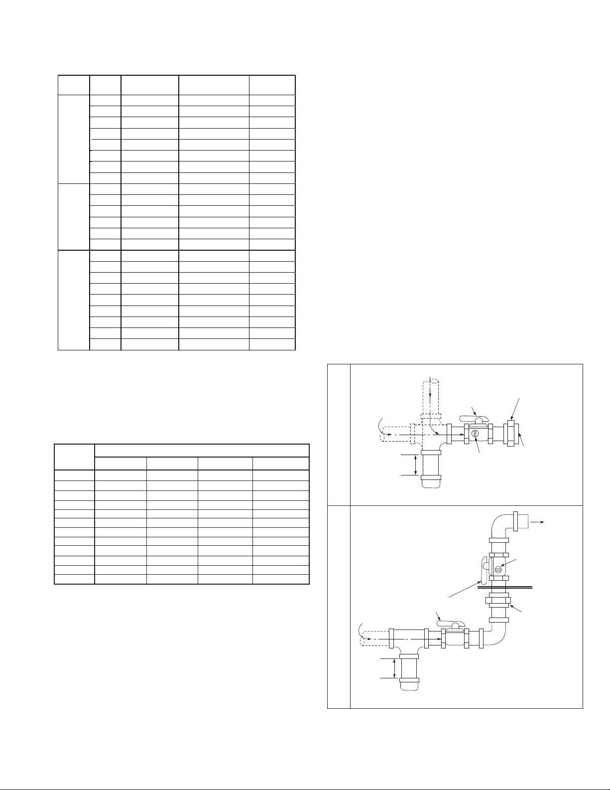
Figure 11.1 - Recommended Sediment Trap/Manual
Shut-off Valve Installation
GAS
SUPPLY LINE
SUPPLY LINE
MANUAL GAS
SHUT-OFF VALVE
GROUND JOINT
UNION WITH
BRASS SEAT
Table 11.2 - Gas Pipe Capacities (Cu. Ft. per Hour) m
Pipe
Length
(feet)
1" 1-1/4" 1-1/2" 2"
10 520 1050 1600 3050
20 350 730 1100 2100
30 285 590 890 1650
40 245 500 760 1450
50 215 440 670 1270
60 195 400 610 1150
70 180 370 560 1050
80 170 350 530 990
90 160 320 490 930
100 150 305 460 870
125 130 275 410 780
150 120 250 380 710
m Gas pipe capacities based on gas pressure up to 14" W.C. through Schedule
40 pipe with a pressure drop of 0.3" W.C. for Natural gas with a specific
gravity of 0.60.
Gas Pipe Diameter
TO GAS
CONTROLS
MIN.
3"
PLUGGED
1/8" NPT TEST
GAUGE CONNECTION
Side Gas Connection
SEDIMENT
TRAP
CONTROLS
PLUGGED 1/8"
NPT TEST GAUGE
CONNECTION
Through hole
in bottom of unit.
(caulk hole to prevent
GROUND
JOINT
UNION
W/ BRASS
SEAT
water leakage.)
MANUAL GAS
SEDIMENT
TRAP
SHUT-OFF VALVE
GAS
SUPPLY LINE
Bottom Gas Connection
j Valve is in the “OFF” position when handle is perpendicular to pipe.
MIN.
3"
j
TO
11MCP15-500.7
GAS HEATING OPTION VENT TERMINALS AND COMBUSTION AIR HOODS
Vent
Terminals
Combustion
Air Hoods
6
Type
Field Installe d Qty
(Btu/hr)
18
Vent Terminals and Combustion Air Hoods
1. Do not operate the units without the factory supplied (shipped
loose) power exhauster vent system/vent termination(s) or
combustion air hoods if applicable. Refer to Table 12.1 to
determine how many terminals and hoods are required based
on the model MPR nomenclature.
2. Do not modify or obstruct the combustion air inlet louvers or
the power exhauster discharge cover terminations.
3. Do not add any vents other than those supplied by the
manufacturer. For units that require vent extension kits, refer
to Literature #MCP15-574, “Installation Instructions,
Extended Vent Kit, Model MPR Gas Heat”.
Table 12.1 - Power Exhauster Vent Terminal and
Combustion Air Hood Quantity
Digit
B
C
D
Furnace Size
Digit
F 150,000
G 200,000
H 250,000
J 300,000
K 400,000
R 175,000
S 225,000
T 310,000
J 300,000
K 400,000
L 500,000
L 600,000
U 350,000
V 450,000
K 400,000
L 500,000
M 600,000
Q 800,000
1 900,000
2 1,000,000
3 1,200,000
4 1,400,000
5 1,600,000
Furnace
Non-
Condensing
Condensing
Non-
Condensing
Condensing
Non-
Condensing
Non-
Condensing
1
1 n/a
2
2
2 2
4 2
n/a
n/a
n/a
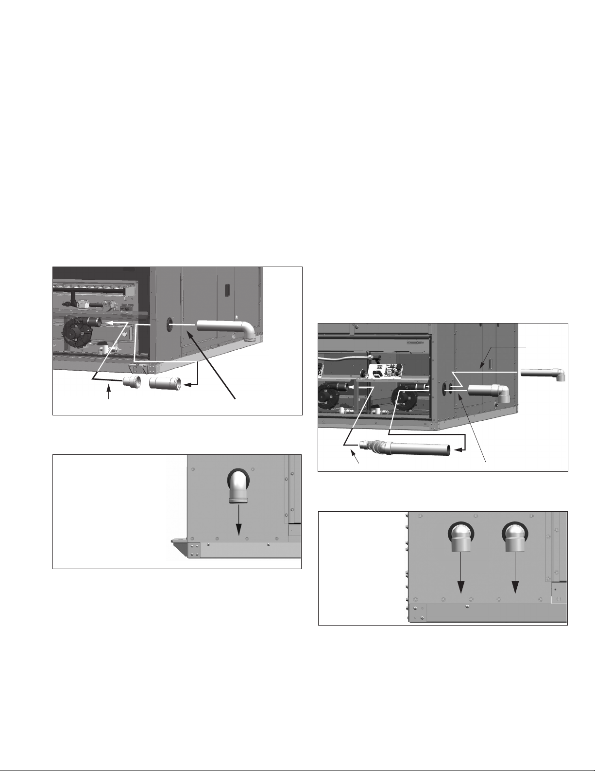
Non-Condensing Furnaces (B, C, or D-Cabinet)
For Non-Condensing furnace types, as determined from Table
12.1, refer to Figure 12.1 for vent termination installation details,
otherwise skip to the section titled Condensing Furnaces. For
units that require vent extension kits, refer to Literature
#MCP15-574, “Installation Instructions, Extended Vent Kit,
Model MPR Gas Heat”.
Figure 12.1 - Power Exhauster Vent Terminal for
Non-Condensing Gas Furnace Option
Note: Caulk mating
surfaces before
2
Gas Furnace
Vent Outlet
k C-Cabinet sized unit shown with two vent terminals. B-Cabinet sized units
have only one and D-Cabinet with have either one on each side of the
cabinet (two total) or two on each side of the cabinet (four total).
attaching to the unit
(6) Screws for
Fastening Gas
Furnace Vent
Outlet Cover
(supplied with kit)
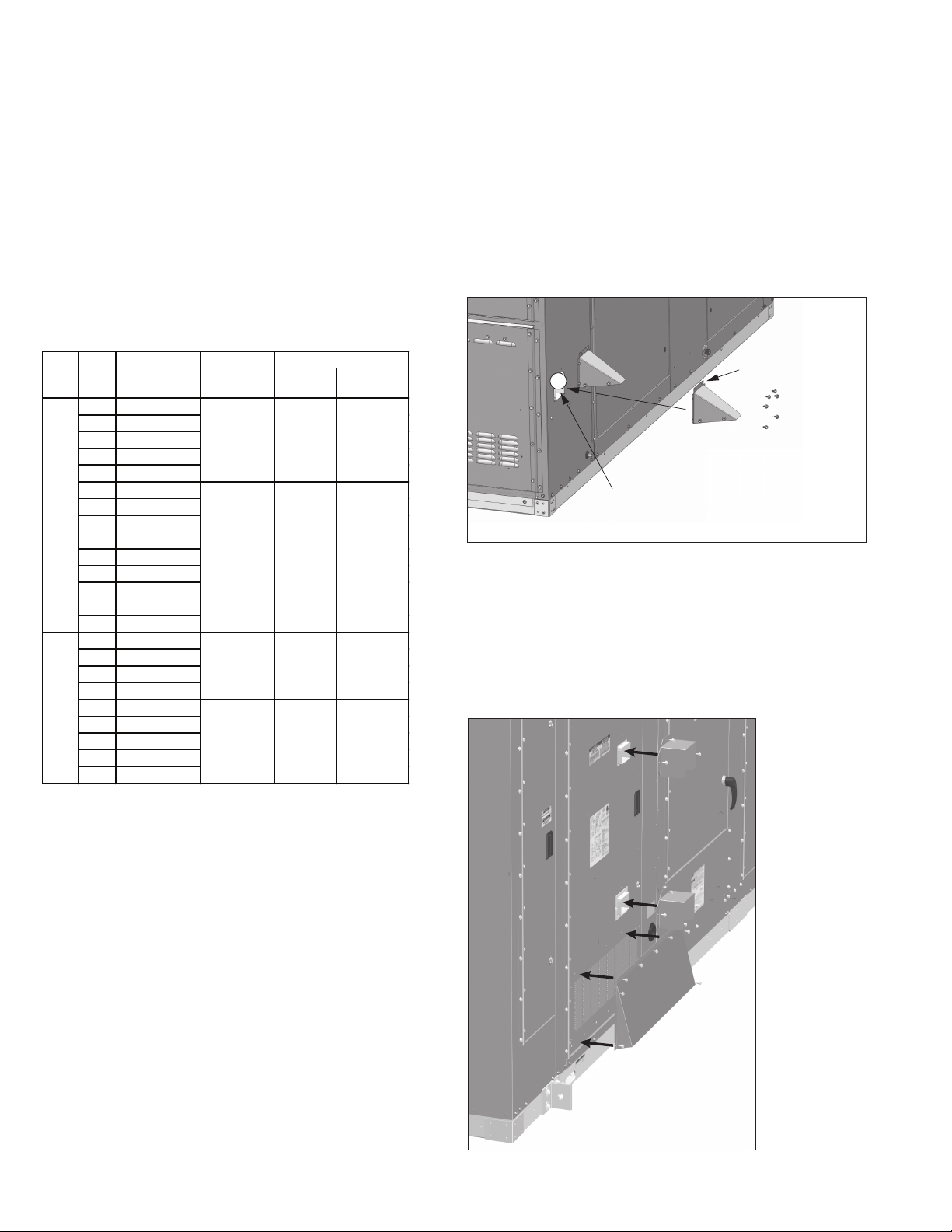
For D-Cabinet units, the furnace doors must have the
combustion air hoods field installed as shown in Figure 12.2,
using the screws included with the kit. Once complete, proceed
to the “Start-Up” section.
Figure 12.2 - Combustion Air Hood Installation
(D-Cabinet only)
For specific instructions on each configuration in Table 12.1,
refer to the appropriate section from the following sections
titled:
• Non-Condensing Furnaces (B, C, or D-Cabinet), or
• Condensing Furnace (B-Cabinet), or
• Condensing Furnace (C-Cabinet)
12 MCP15-500.7
Note: Caulk mating surfaces
before attaching to the unit.
Also shown are the vent terminals for reference.
(refer to
Instructions
Step 1)
(refer to Instructions Step 3)(refer to Instructions Step 2)
(refer to Instructions Step 1) (refer to Instructions Step 2)
GAS HEATING OPTION VENT TERMINALS AND COMBUSTION AIR HOODS
Condensing Furnaces (B-Cabinet)
For B-Cabinet units with Condensing furnace types, as
determined from Table 12.1 on page 12, refer to Figures 13.1
and 13.2 for vent termination installation details. The
installation steps are as follows:
Step 1: Insert short vent pipe length into the vent pipe
reducer. Insert that assembly into the rubber coupling
on the power exhauster outlet. Tighten the clamp on
the flexible coupling to secure the vent pipe.
Step 2: Insert the outer vent pipe with termination elbow
through the enclosure wall grommet and into the vent
pipe section installed in Step 1.
Once complete, proceed to the “Condensate Drain and Trap
Installation” section.
Condensing Furnaces (C-Cabinet)
Figure 13.1 - Power Exhauster Vent Terminal for
Condensing Gas Furnace Option
For C-Cabinet units with Condensing furnace types, as
determined from Table 12.1 on page 12, refer to Figures 13.3
and 13.4 for vent termination installation details. The
installation steps are as follows:
Step 1: Insert small diameter outside vent pipe termination
through enclosure wall grommet and into the flexible
rubber coupling on the right side power exhaust
outlet. Tighten the clamp on the flexible coupling to
secure the vent pipe.
Step 2: Insert large diameter inner vent pipe assembly into
the flexible rubber coupling on the left side power
exhaust outlet. Tighten the clamp on the flexible
coupling to secure the vent pipe.
Step 3: Insert large diameter outside vent pipe termination
through enclosure wall grommet and into the
interlocking joint of the inner vent pipe assembly from
Step 2.
Step 4: Verify that the bird screens are inserted in the outlet
elbow.
Once complete, proceed to the “Condensate Drain and Trap
Installation” section.
Figure 13.3 - Power Exhauster Vent Terminal for
Condensing Gas Furnace Option
Figure 13.2 - Orientation of Installed Vent Terminal
for Condensing Gas Furnace Option (B-Cabinet)
Discharge Elbow must be
oriented to exhaust
straight down.
Figure 13.4 - Orientation of Installed Vent Terminal
for Condensing Gas Furnace Option (C-Cabinet)
Discharge Elbows must
be oriented to exhaust
straight down.
13MCP15-500.7
3/4" Threaded Elbow on Heat Exchanger Drain
Assembly (included with kit)
3/4" Male Threaded PVC Adapter
(included with kit)
3/4" PVC Pipe (by others) with Sufficient Length
to Reach the Heat Exchanger Drain Assembly
from the Inside of the Building
3/4" Unions (by others)
Recommended for Ease of Future Service
PVC "EZ-Trap" (included with kit) for
Proper Drain Trapping (a 3/4" to 1" bushing
by others may be required)
Note: The trap must be located in a heated
space or protected to avoid freezing.
Vacuum Breaker and Drain Piping
Components (by others)
To Building
Drain System
From Heat
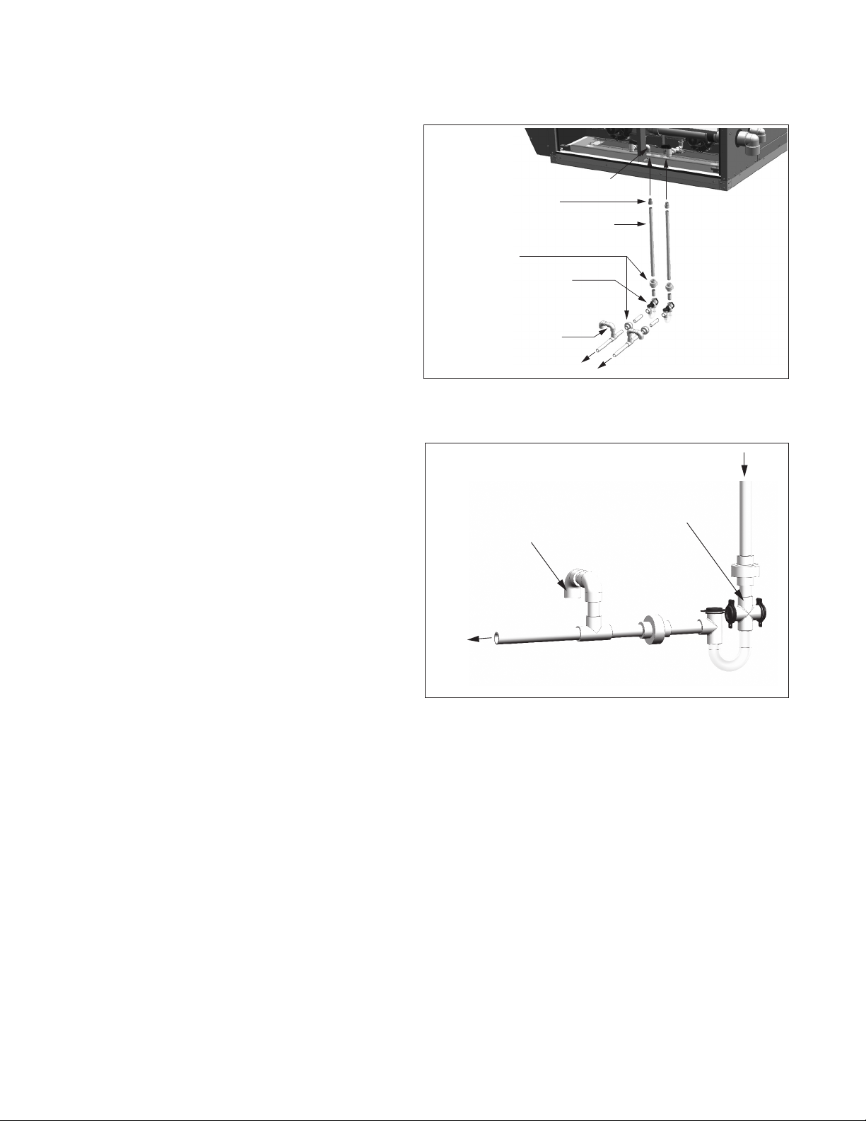
GAS HEATING OPTION CONDENSATE DRAIN AND TRAP INSTALLATION
Condensate Drain and Trap Installation
(Condensing Furnace Type Only)
For Condensing furnace types, as determined from Table 12.1
on page 12, during heating operation, condensate is produced
in the furnace sections. The installation requires condensate
drain systems from each furnace section, as shown in Figures
14.1 and 14.2 and described below. Condensate trap kits are
provided with the unit.
1. For proper heating system performance, the condensate
drain system must include a trap for each furnace.
B-Cabinet units have one furnace while C-Cabinet units
have two furnaces.
2. All joints must be watertight to prevent leakage of
condensate. The drains must be extended down through
the base of the unit and into the heated space below.
3. Each heat exchanger drain assembly includes a threaded
elbow that is oriented down. Once the male threaded PVC
adapters, included with the kit, are glued to the PVC drain
pipe (by others) that extends into the space, they are to be
routed up through the holes in the unit base pan and
screwed into the elbow connections. The threads must be
sealed to prevent leaks.
4. Unions are recommended to permit maintenance of the
drains and to facilitate service of the heater. A union is
shown on both sides of each trap.
5. A vacuum breaker is required after each trap. The vacuum
breaker should be constructed so that dirt and debris do
not enter and clog the drain system.
6. Local code permitting, the condensate drain systems may
be joined after the traps and connected to a sanitary drain
within the building. Because the condensate produced is
acidic, some municipalities may require that the
condensate be neutralized before being discharged into the
sanitary sewer. A condensate neutralizer tube kit is
available from Modine to reduce the pH of the condensate.
A single tube can be used for drains that are joined after
the traps providing the tube is installed after the junction.
Refer to the instructions that come with the kit.
7. For proper operation, the traps must be primed with water.
The traps must be installed with the higher side connected
to the heater and the lower side connected to the drain.
8. If there is an opportunity that the temperature in the space
will fall below freezing during non-operating periods, the
condensate drain systems and secondary heat exchanger
must be completely drained to prevent freeze damage.
Alternately, heat tape can be applied to the drain pipe
system in accordance with the heat tape manufacturers
instructions.
Figure 14.1 - Furnace Condensate Drain/Trap
System j
j C-Cabinet sized unit shown with two condensate drain systems. B-Cabinet
sized units require only one drain system.
Figure 14.2 - Drain System Trap/Vacuum Breaker
Exchanger Drain
Assembly on Unit
Note: Drain pipe from unit
Vacuum Breaker
To Building
Drain System
Note: Refer to figure above for determination of parts supplied by others.
must enter the high side of
the drain trap.
14 MCP15-500.7
HOT WATER PIPING CONNECTIONS
REVIEW BEFORE PROCEEDING
THIS SECTION APPLIES TO UNITS WITH
OPTIONAL HOT WATER HEAT
(MODEL DIGIT 17=4).
IF THE UNIT DOES NOT HAVE HOT WATER
HEAT, SKIP TO PAGE 16.
CAUtIoN
1. Units not approved for use in potable water systems.
2. Do not operate the unit with steam. The coil is not designed
for steam condensate removal which can damage the unit.
3. Hot water supplied to the hot water heating option must
not exceed 180°F temperature or 75 PSIG pressure.
1. Models with a factory installed hot water heating coil (for use
with water or propylene glycol fluids) are supplied with 1-1/2"
sweat connections (1.625").
Figure 15.1 - Hot Water Coil Connections
•On3-wayvalvecontrolconfigurations,includeabalancing
valve between the supply line and control valve to balance
the system.
•Includeahosebibdrainvalveonthebottomofthesupply
manifold to allow for periodic flushing of the system to
remove sediments from the coil.
•Includeapipelinestraineronthesupplylinetoprevent
sediment from reaching the coil.
•Includeanairventatthetopofthereturnmanifoldtobleed
off accumulated air in the system. Air in the system will
generate noise and may cause water hammer that can
damage the joints of the piping and coil.
•Includeeithera2-wayor3-waymodulatingcontrolvalve
designed for a 0-10VDC control signal. The valves will be
automatically modulated by the unit’s Carel controller to
maintain the supply air temperature setpoint. Note that the
control valve must be a normally open, spring return type
valve. This is to allow hot water to flow through the coil for
freeze protection when the unit is shut down. Refer to the
Freeze Stat Option section for additional detail.
•Hotwaterpipesshouldbeinsulatedtoreduceheatlossand
to prevent overheating of the end compartment.
9. Leak test the coil and connections as outlined in the
Start-Up section.
Figure 15.2 - Typical 2-Way Piping Installation
(piping and components by others)
Supply Connection Return Connection
2. The entering water temperature (EWT) supplied to the
heating coil must not exceed 180°F.
3. The fluid flow rate must not exceed 50 gallons/minute (GPM)
and fluid pressure must not exceed 75 psi.
4. It is recommended to use an inhibited glycol solution that is
designed for HVAC applications for corrosion protection and
freeeze protection for the lowest possible outside air
temperatures for the installed location. Failure to protect
against freezing can result in damage to the coil and
property.
5. Provide adequate pipe hangers, supports, or anchors to
secure the piping system independently of the coil to prevent
excess vibration and stress that can damage the piping and
joints.
6. All field brazing and welding should be performed using high
quality materials and an inert gas purge (such as nitrogen) to
reduce oxidation of the internal surface of the coil.
7. System piping should be flexible enough to allow for thermal
expansion and contraction of the coil and piping components.
8. Refer to Figures 15.2 and 15.3 for typical piping system
design and the following recommended items:
•Installshut-offvalvesinlinestoandfromtheunittoallow
for maintenance or replacement of the coil without shutting
down and draining the entire system.
•Installunionsforeaseofpipingcomponent/coilremoval.
•Includeacircuitsetterinthereturnlinetoregulateflow.
HOSE BIB DRAIN
SHUT-OFF
VALV E
SHUT-OFF
VALV E
SUPPLY
RETURN
HOT WATER
COIL
AIR VENT
UNION
UNION
2-WAY CONTROL
VALV E
STRAINER
UNION
CIRCUIT
SETTER
Figure 15.3 - Typical 3-Way Piping Installation
(piping and components by others)
HOSE BIB DRAIN
SHUT-OFF
VALV E
SHUT-OFF
VALV E
SUPPLY
RETURN
HOT WATER
COIL
AIR VENT
UNION
UNION
BALANCING
VALV E
3-WAY CONTROL
VALV E
UNION
STRAINER
UNION
CIRCUIT
SETTER
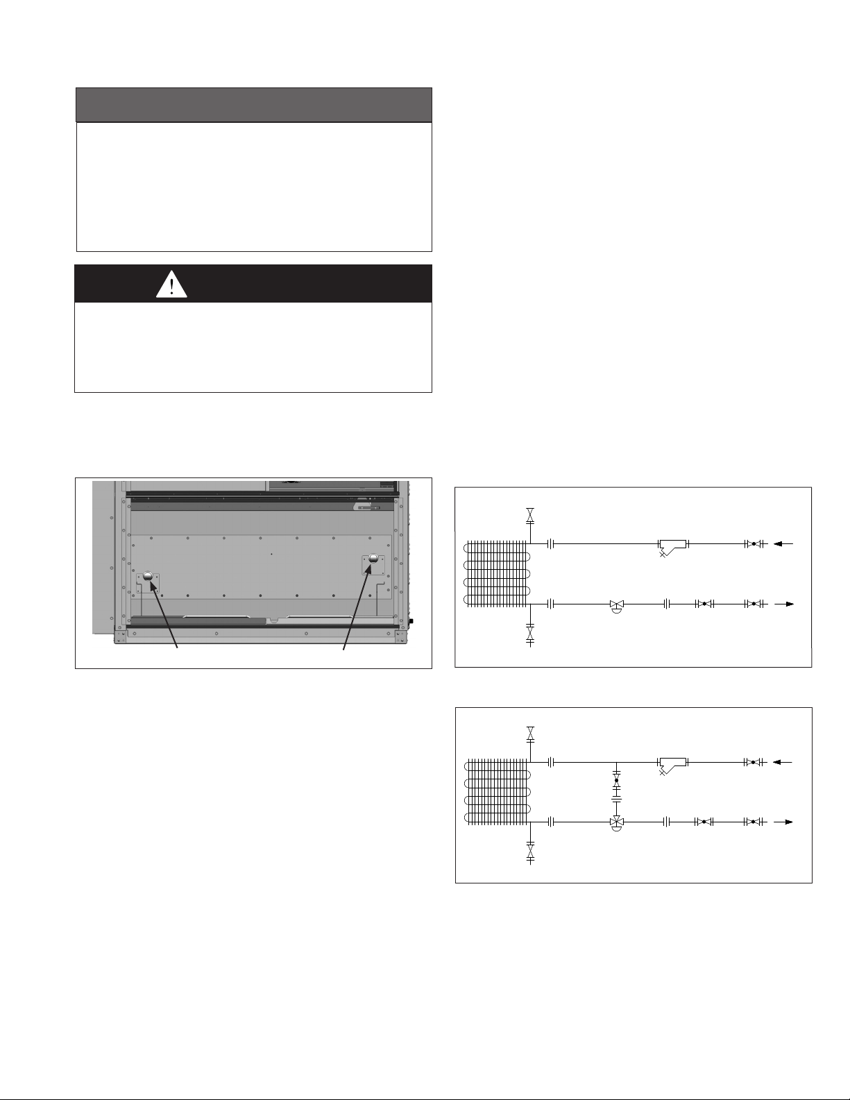
Optional Factory Installed Freeze Stat
When equipped with the optional Coil Freeze Stat, an autoresetting capillary type freeze stat (see Figure 50.1) is factory
installed immediately below and across the face of the hot
water coil. The stat is set to trip at 40°F (adjustable) and will
automatically reset when the coil temperature rises 5°F above
the setpoint. If the stat has tripped, the unit controls would
respond by closing the outdoor air damper, opening the return
air damper (if applicable), de-energize the supply air fan, open
the hot water coil valve 100%, and log the alarm on the
controller. The freeze stat can be removed from the unit for
servicing as discussed in the Maintenance section.
15MCP15-500.7
START-UP PROCEDURE
General
1. When the dead front disconnect switch(es) (for main
unit and/or powered convenience outlet option) is in the
“OFF” position, supply power remains energized at the
line (supply) side of the dead front disconnect switch(es).
The switch body is located inside of another junction
box to protect against contact with the live wiring.
The junction box must not be disassembled unless
the main power supply from the building to the unit is
de-energized.
2. For units equipped for dual power supply sources, both
sources of power must be disconnected to prevent
electrical shock and equipment damage.
WARNING
WARNING
CAUtIoN
When servicing the unit, some components may be hot
enough to cause pain or injury. Allow time for cooling of hot
components before servicing.
IMPoRtANt
1. To prevent premature heat exchanger failure, check to
be sure the blower has been set to deliver the proper
airflow for the application. Refer to page 17 for Blower
Adjustments.
2. Start-up and adjustment procedures must be performed
by a qualified service agency.
3. All scroll compressors requires the correct supply
power phase rotation. Phase reversal may result in
compressor failure not covered under warranty. Refer to
the Start-Up Procedure section.
4. The exhaust fan is not designed for high temperature
or smoke control exhaust applications. Exhaust air
temperature must not exceed 104°F. Operating the
exhaust fan above 104°F will result in failure of the
exhaust fan.
1. Turn off power to the unit at the disconnect switch. If
equipped with gas heating option, turn all hand gas valves
to the “OFF” position.
Note: The dead front disconnect switch, if included, is
factory installed in the controls/compressor compartment
section (refer to the figures on pages 32 through 35). The
disconnect switch is designed so that it must be turned
“OFF” before entry to the compartment can be obtained.
When in the “OFF” position, power is disconnected to all
unit wiring electrically following the switch (see
WARNING).
2. For units equipped for dual power supply sources, both
sources of power must be disconnected to prevent
electrical shock and equipment damage.
3. Open the power compartment, controls compartment, and
blower access doors.
4. Check that the supply voltage matches the unit supply
voltage listed on the Unit Serial Plate. For units equipped
for dual power supply sources, the voltage on both the
main feed and the auxiliary feed must match the unit
supply voltage listed on the Unit Serial Plate.
5. Check that fuses or circuit breakers are in place and sized
correctly.
6. Verify that all wiring is secure and properly protected. Trace
circuits to ensure that the unit has been wired according to
the wiring diagram.
7. Check that all electrical and gas connections are
weatherized.
8. For C-Cabinet sized units, if the unit is installed with a
Modine supplied Energy Recovery Module, Model ERM,
verify that the wiring connection between the MPR unit and
the ERM unit has been properly installed. If the unit is a
B-Cabinet sized unit with integral Energy Recovery, the unit
is already factory wired to the Energy Recovery section.
9. For units with gas heating, check to ensure that the
combustion air inlet louvers and the power exhauster
discharge cover (Non-Condensing as determined from
Table 12.1 on page 12) or the vent elbow terminations
(Condensing as determined from Table 12.1 on page 12)
are free from obstructions.
10. For units with condensing gas heating, check that the
condensate drain system is properly installed and the trap
has has been primed with water.
11. For units with Hot Water Heat (Digit 17=4), check the
following:
• Open air vents so that air is eliminated from within the coil
circuitry and headers. Verify that vents and drains are not
obstructed and do discharge a stream of water.
• Open all required valves to fill the coil. Once the coil is
full, close all air vents.
• Perform an initial hydrostatic leak test of all brazed,
threaded or flanged joints, valves and interconnecting
piping, and the hot water coil. Recheck the coil level and
correct if necessary.
• When the setup is found to be leak free, flush the coil
through the drain valve to eliminate grease, oil, flux and
sealing compounds present from the installation.
• Recheck the coil and all connections for water leaks.
• Check water flow rates and pressure drops and compare
to design.
• Check that the hot water supplied to the coil does not
exceed 180°F temperature or 75 PSIG pressure. Verify
that the appropriate glycol mixture is used for freeze
protection.
12. Check to see that there are no obstructions to the intake
and discharge of the unit.
13. Verify that the belts are aligned in the sheave grooves
properly and are not angled from sheave to sheave.
14. On belt driven blowers, blower bearings are permanently
lubricated unless they are pillow block bearings or if they
have grease fittings. For motors or blower bearings that are
not permanently lubricated, lubricate according to the
manufacturer’s instructions. Refer to the Maintenance
section on page 48.
15. Check to make sure that all filters are in place and that
they are installed properly according to direction of air flow.
Pleat direction must be vertical to ensure optimum
performance.
16. Perform a visual inspection of the unit to make sure no
damage has occurred during installation.
16 MCP15-500.7

START-UP PROCEDURE - CONTINUED
17. Check that the evaporator drain pan drain trap has been
primed with water.
18. Turn on power to the unit at the disconnect switch.
Note: Units include one blower door switch per access
door (one on B- and C-Cabinet, two on D-Cabinet) that are
factory installed inside the blower access section door(s).
When a blower section door is opened, the switch is
opened and interrupts power to the low voltage circuit and
de-energizes the blower motor controller. D-Cabinet units
also have the same switches on the evaporator/hot gas
reheat coil access sections.
19. Check the Carel microprocessor controller and supply fan
blower motor for electrical operation. If the unit is equipped
with the optional building power exhauster module (with or
without energy recovery), check the blower motor for
electrical operation. If these do not function, recheck the
wiring diagram. Check to ensure that none of the Control
Options (for example, smoke detector, etc.) have tripped.
20. Check to make sure that the damper(s) operate properly
without binding.
21. Check that the supply power wiring is wired with the
correct phase rotation. For units equipped for dual power
supply sources, correct phase rotation must be verified on
both the main feed and the auxiliary feed. Incorrect phase
rotation can damage the equipment. Check the phase
rotation as follows:
• For units equipped with single speed motor
starters on the supply fan: Check the blower wheel
for proper direction of rotation when compared to the
air flow direction arrow on the blower housing. Blower
wheel rotation, not air movement, must be checked as
insufficient air will be delivered if the blower wheel is
running backwards. If the blower wheel is rotating in
the opposite direction, the phase reversal must be
corrected by changing the incoming power feed legs at
the supply to the unit, NOT the individual components
on the unit. Recheck for proper rotation.
• For units equipped with a variable frequency drive
on the supply fan: The VFD will correct the phase
rotation for the supply fan, but will not correct the phase
rotation for the rest of the unit, therefore observing the
supply blower wheel rotation direction is not an
accurate indicator of correct phase rotation. Scroll
compressors will only compress in one rotational
direction. Verification of proper rotation direction is
made by observing that suction pressure drops and
discharge pressure rises when the compressor is
energized. Reverse rotation will result in no pressure
differential as compared to normal values. There is no
negative impact on durability caused by operating the
compressors in the reversed direction for a short period
of time (under one hour) but should not be allowed to
operate longer than the time it takes to verify rotation.
If the compressor is rotating in the opposite direction,
the phase reversal must be corrected by changing the
incoming power feed legs at the supply to the unit,
NOT at the compressor. Recheck for proper rotation.
22. Check the blower speed (rpm). Refer to Blower
Adjustments for modification.
23. Check the motor speed (rpm).
24. Check the motor voltage. On three phase systems, check to
make sure all legs are in balance.
25. Check the motor amp draw to make sure it does not exceed
the motor nameplate rating. Check all legs to ensure system
is balanced.
26. For units equipped for dual power supply sources, the unit
should be started separately on the main power feed and
again on the auxiliary power feed to verify proper unit and
control operation.
Note: Units equipped for dual power supply sources have the
unit power wiring separated into two circuits as follows:
Circuit #1
• Compressors
• Condenser fans
• Electric heating section (if applicable).
• Energy recovery wheel (if applicable)
Circuit #2
• Main unit controller
• Supply fan
• Dampers
• Gas heating section (if applicable)
• Exhaust fan (if applicable)
• Energy recovery wheel bypass damper (if applicable)
When operating in a full power state with the main power
feed, both Circuit #1 and Circuit #2 should be powered.
When operating in a low power state with the auxiliary power
feed, only Circuit #2 should be powered.
Blower Adjustments
The units are designed for ease of airflow adjustments, within a
range, for field balancing against actual external static pressure
conditions. If the static pressure external to the unit is above
or below the original design point for the unit, the blower will
deliver an airflow volume that is lower or higher than required.
When equipped with the building exhaust option (with or
without energy recovery), the air balancing must be performed
for both the main unit supply fan, as well as the exhaust fan.
The blower speed (supply and/or exhaust blowers) may be
adjusted to achieve the desired air volume, provided:
• The allowable temperature rise range and the maximum
supply air temperature for heating is not exceeded as
shown in Table 18.1, and
• The airflow is within the allowable limits shown on the
serial plate for both heating and cooling, and
• The total static pressure does not exceed the limit shown
on the unit serial plate, and
• It is within the range of adjustability for the unit, and
• The motor amp draw must not exceed the motor
nameplate rating.
The blower speed adjustment method is dependant on the
following configurations:
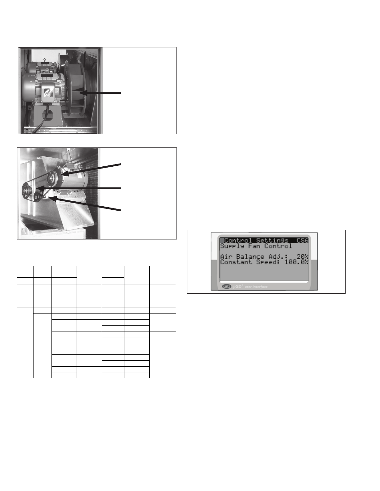
• Direct Drive where the blower is driven directly by the
motor as seen in Figure 18.1. This is the current
standard supply fan configuration for all units.
• Belt Drive where the blower is driven by the motor with a
belt and sheaves as seen in Figure 18.2. This is the
current standard exhaust fan configuration (if equipped)
for all units. It was also used on supply fans for units
shipped before 2018.
Once the blower/motor configuration of the unit is determined,
follow the appropriate instructions in the sections on the
following pages.
17MCP15-500.7
START-UP PROCEDURE - CONTINUED
Figure 18.1 - Direct Drive Blower Example
Direct Driven Blower
(dual blower shown)
Figure 18.2 - Belt Drive Blower Example
Motor Sheave
(adjustable)
Blower Sheave
(non-adjustable)
Automatic Belt
Tensioner
Blower Adjustments – Direct Drive Fans
All direct drive supply fan speed adjustments can be performed
with the Modine Control System programmable microprocessor
controller. There are two ways to access the menus:
1. Using the user interface on the main unit controller.
2. Using the pGD1 Digital Display/Interface Module.
For guidance on either method above, refer to the latest
revision of the following documents for additional warnings,
cautions, controller location, instructions, and menu navigation:
• ControlsManual,MCP15-525.
• pGD1DigitalDisplay/InterfaceModuleInstallation
Instructions, MCP15-543.
The blower adjustments are made as follows:
1. Ensure unit is running at the maximum airflow setting for
the control type selected. For example, if the unit has
Multi-Speed or Variable Speed fan control, ensure the unit
is operating at the highest speed setting.
2. On the keypad navigate to menu “G. Service -> f.
SERVICE SETTINGS”. At this menu, you will be prompted
to enter the Service password of 1500.
3. Navigate to “c. Control Settings” and scroll to the “Supply
Fan Control (CS6)” screen. See Figure 18.3.
Table 18.1 - Allowable Temperature Rise Range and
Maximum Supply Air Temperature
Casing
Size
B
C
D
Heat
Type Rating
(for formula)
1 A, B, C, D 1.00 N 1 - 100°F 100°F
F, G, H, J, K 0.81
2 or 3
2 or 3
2 or 3
R, S, T 0.94 N 30 - 100°F 100°F
1 A, B, C, D, E 1.00 N 1 - 100°F 100°F
J 0.81 N 30 - 75°F
K, L, M 0.81
U, V 0.81
1 A, B, C, D, E 1.00 N 1 - 100°F 100°F
K 0.81 L 30 - 75°F
L, M, Q 0.81
1, 4
2, 3, 5 H 60 - 120°F
Eff
0.81
Temp Rise
Allowable
Temp Rise
Range
L 30 - <70°F
H 70 - 100°F
L 30 - <70°F
H 70 - 100°F
L 30 - <70°F
H 70 - 100°F
L 30 - <70°F
H 70 - 100°F
H 70 - 120°F
Max Supply
Air TempDigit 6 Digit 17 Digit 18 Digit 19
130°F
130°F
100°F
130°F
Figure 18.3 - Control Settings Screen CS6
4. Adjust the Air Balance Adj parameter up or down to obtain
the design airflow given the actual static pressure.
5. In the event you are unable to increase or decrease the
motor speed to the desired air balance please consult your
factory representative.
6. Check the motor amps to ensure the maximum motor amp
rating is not exceeded. For units equipped with a VFD,
measure the amps at the incoming lines to the motor. If
the unit has dual supply fans, measure each motor
individually. Verify airflow volume and repeat steps above
for further adjustment.
7. If equipped with gas heat, turn on the gas and initiate
burner operation. For guidance, refer to the Controls
Manual.
8. Verify the temperature rise and supply air temperature of
the heating section do not fall outside the range or exceed
the maximums shown in Table 18.1. Airflow can be
approximated with the following formula:
CFM = (Input Btu/hr x Eff) / (1.08 x Temp Rise)
where Eff (Efficiency) is determined from Table 18.1
18 MCP15-500.7

START-UP PROCEDURE - CONTINUED
Toward Motor
Set Screw
Adjustable Half
of Sheave
Blower Adjustments – Belt Drive Fans
All belt drive supply fan and, if applicable, exhaust fan speed
adjustments can be made with the adjustable sheave on the
blower motor as follows:
1. Turn off power to the unit at the disconnect switch. If
equipped with gas heat option, turn all hand gas valves to
the “OFF” position.
2. Loosen the belt tension and remove the belt.
3. On the motor sheave, loosen the set screw on the side
away from the motor (see Figure 19.1).
Figure 19.1 - Motor Sheave Adjustment
4. To increase the blower speed, turn the adjustable half of
the sheave inward. To decrease the blower speed, turn the
adjustable half of the sheave outward. The sheave half is
adjustablein½turn(180°)increments.Each½turn
represents approximately a 2-5% change in blower speed
and airflow volume.
5. Tighten the set screw on the flat portion of the sheave shaft.
6. Replace the belt and verify that the belts are aligned in the
sheave grooves properly and are not angled from sheave
to sheave.
7. Turn on power to the unit and initiate blower motor
operation. For guidance, refer to the Controls Manual.
8. Check the motor amps to ensure the maximum motor amp
rating is not exceeded. Verify airflow volume and repeat
steps above for further adjustment.
9. If equipped with gas heat, turn on the gas and initiate burner
operation. For guidance, refer to the Controls Manual.
10. Verify the temperature rise and supply air temperature of
the heating section do not fall outside the range or exceed
the maximums shown in Table 18.1. Airflow can be
approximated with the following formula:
CFM = (Input Btu/hr x Eff) / (1.08 x Temp Rise)
where Eff (Efficiency) is determined from Table 18.1
Air Flow Proving Switch / Optional Dirty Filter Switch
The air flow proving switch is factory installed in the blower
compartment. The purpose of the air flow proving switch is to
cut power to the controls if a positive pressure is not measured
by the switch. This could be caused by a lack of air movement
through the evaporator coil or heat exchanger.
The optional dirty filter pressure switch is factory installed in
the filter section. The dirty filter pressure switch monitors the
pressure differential between the two sides of the filters. When
the filters become dirty, the differential pressure increases and
trips the pressure switch which initiates an alarm from the Carel
controller. The pressure differential switch must be field set
because setting the switch requires the blower to be inoperation
and the ductwork to be installed.
Setting the Air Flow Proving or Dirty Filter Switch
1. Ensure that the unit filters are clean. Replace if necessary.
2. Using the Modine Control System controller interface, start
blower operation.
3. Turn the set screw of the pressure switch clockwise until it
stops.
4. With the wires removed from the common and normally
open terminals of the switch, measure continuity and turn
the adjustment screw counter-clockwise until the switch
makes. Then turn the adjustment screw one additional turn
counter-clockwise to account for dirty filters or other system
static changes.
Variable Air Movement Applications
Units may be supplied with variable frequency drives for
applications where variable air volume is required. The
minimum air flow may be varied between 50 and 100% of the
full speed air flow depending on the controls selection of the
unit, but never less than the following:
• B-Cabinet units: 1100 CFM
• C-Cabinet units: 3000 CFM
• D-Cabinet units: 4000 CFM
• All units with Gas Heat: Minimum airflow as listed on the
Gas Heat Serial Plate
Refer to the Controls Manual for additional information.
11. After 24 hours of operation, retighten the setscrews to the
torque listed in the owners manual on the bearing, sheave,
and blower wheel to avoid damage to the unit.
19MCP15-500.7

START-UP PROCEDURE - CONTINUED
Checking Refrigerant Charge
This unit contains R-410A high pressure refrigerant.
Hazards exist that could result in personal injury or death.
Installation, maintenance, and service must only be
performed by an HVAC technician qualified in R-410A
refrigerant and using proper tools and equipment. Due to
much higher pressure of R-410A refrigerant, DO NOT USE
service equipment or tools designed for refrigerants other
than R410A.
Do not overcharge the refrigeration system. This can lead
to elevated compressor discharge pressure and possibly
flooding the compressor with liquid.This may result in
compressor failure not covered under warranty.
WARNING
WARNING
CAUtIoN
IMPoRtANt
1. All refrigeration checks must be made by a qualified
R-410A refrigeration technician.
2. Do not release refrigerant to the atmosphere. When
adding or removing refrigerant, all National, State/
Province, and local laws must be followed.
Refrigerant charge can be verified by checking both superheat
and subcooling. B- and C-Cabinet units have one circuit and
D-Cabinet units have two circuits. The following procedure is
to be done for each refrigeration circuit.
1. Check the evaporator coil to be sure there are no
obstructions to airflow.
2. From the Modine Control System controller interface,
create a call for cooling. If the unit has the hot gas reheat
option, the hot gas reheat valves must be closed.
3. The unit must be operated at near to full load operation
before checking the refrigerant charge. The unit operation
should be stabilized, typically after 10-15 minutes of
operation.
4. Measure subcooling as follows:
a. Read the gauge pressure at the liquid line test port (refer
to the figures on pages 32 through 35). Note the
saturation temperature on the gauge.
b. Measure the temperature of the liquid line at a point
near where the pressure reading was taken.
c. Subtract the measured liquid line temperature from the
saturation temperature to determine the liquid
subcooling. For units without the hot gas reheat option,
the subcooling should be 10-15°F. For units with the hot
gas reheat option, the subcooling should be 5-15°F.
5. Measure the superheat as follows:
a. Read the gauge pressure at the suction line close to the
compressor. Note the saturation temperature on the
gauge.
b. Measure the temperature of the suction line at a point
near where the pressure reading was taken.
c. Subtract the saturated temperature from the measured
suction line temperature to determine the evaporator
superheat. The superheat should be 8-12°F.
6. Determine if the system is undercharged or overcharged
and correct as follows:
a. Undercharged: Typically, superheat is too high and
subcooling is too low. Refrigerant should be added.
b. Overcharged: Typically, superheat is too low and
subcooling is too high. Refrigerant should be removed.
7. After adding or removing refrigerant, allow the system to
stabilize for 10-15 minutes before making any other
adjustments.
8. Repeat the steps above until the subcooling and superheat
are within the range specified.
9. Repeat the above procedure for the 2nd circuit on
D-Cabinet units.
10. Once the correct charge has been established, operate the
unit reheat mode to verify correct operation.
Table 20.1 - Refrigerant Charge
Casing Size Unit Tons
07
10
B
C
D
13
15
20
15
20
26
30
30
40
52
60
Hot Gas
Reheat
0 17.0
1 or 2 20.0
0 17.0
1 or 2 20.5
0 23.0
1 or 2 28.5
0 24.0
1 or 2 28.5
0 28.5
1 or 2 35.5
0 35.0
1 or 2 39.0
0 37.0
1 or 2 42.0
0 38.0
1 or 2 44.0
0 39.0
1 or 2 46.0
0 34.5
1 or 2 45.0
0 36.0
1 or 2 46.5
0 Future
1 or 2 Future
0 Future
1 or 2 Future
Refrigerant
Charge per
Circuit (lbs.) # of CircuitsDigit 6 Digits 4-5 Digit 10
1
1
2
20 MCP15-500.7

START-UP PROCEDURE - CONTINUED
REVIEW BEFORE PROCEEDING
THIS SECTION APPLIES TO UNITS WITH
OPTIONAL GAS HEAT
(MODEL DIGIT 17=2 OR 3).
IF THE UNIT DOES NOT HAVE GAS HEAT,
SKIP TO PAGE 28.
Gas Heating Option
The Gas Heating Option requires gas pressure be measured
and adjusted as required at several points on the unit. The
following steps must be completed:
Identify the Gas Control Type
Before you begin, review the furnace serial plate to determine
the model installed. The serial plate is located on the right hand
access door for the furnace section. Refer to Pages 56 through
59 for Serial Plate and Model Nomenclature information. Note
that the furnace serial plate is separate from the unit (model
MPR) serial plate.
Digit 11 of the furnace model number denotes the type of gas
control used. These are defined below:
4 - Indicates two heat exchangers using basic modulating
controls with United Technologies ignition. Manifold
pressure of both heat exchangers is varied
simultaneously based on demand. Power exhausters
operate at a constant speed.
6 - Indicates a single heat exchanger with Beckett advanced
modulation control which varies the manifold pressure
and power exhauster speed based on demand. High
turn down and more consistent efficiency are possible
with this control.
8 - Indicates two or more heat exchangers; one equipped
with advanced Beckett modulation master control and
the other(s) equipped with non-modulating single input
slave control. The slave heat exchanger(s) is controlled
and monitored by the master control and will turn on or
off depending on demand.
Check/Adjust Pressure Upstream of Unit
With the field installed manual gas shut-off valve in the “OFF”
position, recheck the gas supply pressure at the field installed
manual shut-off valve. The inlet pressure should be 6"-7" W.C.
on natural gas, while all the burners are operating, but never
more than 14" W.C when the burners are off. If inlet pressure is
too high, install an additional pressure regulator upstream of the
combination gas control.
Check/Adjust Pressure at Combination Gas Valve
1. Open the field installed manual gas shut-off valve and set
the combination gas control valve to the “ON” position. Note
for C- and D-Cabinet sized units, the Gas Heating Option
consists of two or more heating sections. For this step, only
one combination gas valve is to be set to the “ON” position.
2. Enable the unit controls. For furnace models with furnace
model Digit 11=6, the LED readout on the furnace control
board (Figure 23.1) will briefly display the furnace size.
Verify that the model readout is correct for the unit being
started.
3. Ensure that the supply fan blower is operating at the proper
airflow and adjust the Modine Control Systemc control
setpoint to create a call for heat. Refer to the Controls
Manual for instructions on changing the setpoint.
4. Check the ignition control and gas valve for electrical
operation.
5. Check to make sure that the main gas valve opens while
the supply fan blower is operating.
6. Check the gas pressure at the INLET to the combination
gas control valve (refer to figures on pages 24 through
26) and adjust as needed to maintain 6"-7" W.C while the
burners are operating at high fire. This pressure is required
for proper ignition and to attain the rated input of the unit.
If this pressure cannot be obtained, the gas supply is
undersized and needs to be corrected or the gas supplier
must be contacted.
7. Check gas pressure on the OUTLET of the combination
gas control valve (refer to figures on pages 24 through 26)
when the burners are functioning. This should be set to 4.0"
W.C. for all furnaces with furnace model Digit 11=4, or 6.
For C-Cabinet furnaces with furnace model Digit 11=8, only
the right hand modulated heat exchanger is set to 4.0”W.C.
The left hand fixed input heat exchanger is set to 3.5”W.C.
Adjust the gas control valve regulator as needed (see gas
valve instruction sheet for location.)
8. Check to ensure that gas controls sequence properly (see
Controls Manual).
9. For units with multiple heat exchangers, repeat steps 3
through 8 for each heat exchanger before proceeding to the
next step.
Check/Adjust Pressure at Manifold
The following steps are required to check/adjust the manifold
pressure on modulated heat exchangers. For units with furnace
model Digit 11=4, this process applies to both heat exchangers
and is conducted on one heat exchanger at a time. For all
other units, this process applies to only one heat exchanger,
normally the lower right heat exchanger on multiple heat
exchanger units.
1. Move the field installed manual shut-off valve to the “OFF”
position.
2. Remove the 1/8" pipe plug in the pipe tee of the furnace.
3. Attach a digital or “U” tube type water manometer which is
at least 12" high and capable of reading to 0.1" W.C.
4. The Maxitrol EXA modulating valve series (refer to figures
on pages 24 through 26) has a cover secured with two
screws that must be removed. Once removed, there
are a bank of (3) DIP switches and two buttons and a
communication LED for the user interface as shown in
Figure 22.1.
5. Verify that the DIP switches are properly set to the settings
shown in Figure 22.1.
6. Move the field installed manual gas shut-off valve to the
“ON” position.
7. Adjust the High Fire Setting as follows:
a. Enable the unit controls.
b. For units with furnace model Digit 11=6 or 8, place
the furnace control into the “Checkout Test Mode” as
described on the next page and set the Fire Rate Input
to 10.0.
c. Press and hold Button #1 on the modulating valve until
the LED lights solid red, then release.
d. With the valve now in the high fire setting mode, confirm
21MCP15-500.7

START-UP PROCEDURE - CONTINUED
or adjust the high fire manifold pressure to be 3.5" W.C.
If the pressure needs to be adjusted, press or hold
Button #1 to increase gas flow and press or hold Button
10. For furnace models with Digit 11=6 or 8, verify the furnace
#2 to decrease gas flow.
e. If 3.5" W.C. cannot be attained, recheck the inlet gas
pressure as described previously. After addressing any
issues, if 3.5" W.C. still cannot be attained, step the
valve closed using button #2 to the point where manifold
pressure begins to be impacted. If the pressure at that
• Thehighfiremanifoldpressuremaybeintherangeof
• Thelowfiremanifoldpressuremustnotgobelow
point is less than 3.3" W.C., corrective action is required.
f. Save the setting by simultaneously holding Buttons #1
and #2 until the LED turns OFF. If this is not performed
within 5 minutes, the control will default to the previously
saved settings and return to normal operating mode.
11. Once the setting of the modulating valve has been
Figure 22.1 - Maxitrol Modulating Valve Adjustments
BUTTON #2
SUPPLY POWER
WIRING TERMINALS
CONTROL SIGNAL
WIRING TERMINALS
3 4
1 2
ON
1 2 3
(ONLY ON UNITS WITH FURNACE
Furnace Model
Digit 11
(Capacity Control)
4
6 or 8
BUTTON #1
POSITION FEEDBACK
WIRING TERMINALS
MODEL DIGIT 10=6, 7, OR 8)
DIP SWITCHES
(SEE TABLE FOR SETTINGS)
LED INDICATOR
DIP Switch
Settings
SW #1 OFF
SW #2 OFF
SW #3 OFF
SW #1 OFF
SW #2 ON
SW #3 OFF
8. Adjust the Low Fire Setting as follows:
a. For units with furnace model Digit 11=6 or 8, place
the furnace control into the “Checkout Test Mode” as
instructed in the next section and set the Fire Rate Input
to 2.0.
b. Press and hold Button #2 on the modulating valve until
the LED light blinks red, then release.
c. With the valve now in the low fire setting mode, confirm
or adjust the low fire manifold pressure to be no less than
the minimum shown on the furnace serial plate in the box
called “Min. Manifold Pressure”. If the pressure needs to
be adjusted:
Press or hold Button #1 to increase gas flow and press
Button #2 to decrease gas flow. It is best to push
and release button #2 to single step the valve to the
minimum manifold pressure. Pressing and holding the
button is likely to cause the valve to close too far and
lose flame.
d. Save the setting by simultaneously holding Buttons #1
and #2 until the LED turns OFF. If this is not performed
within 5 minutes, the control will default to the previously
saved settings and return to normal operating mode.
9. For furnace models with Digit 11=6 or 8, if no errors or
alerts were recorded by the board (these will be on the
3 LED displays as an “A” or “E” followed by a number),
proceed to the next step. If any alerts or errors were logged
by the board, refer to the “Clearing Furnace Control Board
22 MCP15-500.7
12. Move the field installed manual shut-off valve to the “OFF”
13. After the plug is in place, move the field installed manual
14. For units with furnace model Digit 11=4, repeat the entire
Placing Furnace Control Into “Checkout Test Mode”
(Applies to furnace models with Digit 11=6 or 8)
The furnace control board (Figure 23.1) has functionality to be
put it in a manual operation “Checkout Test Mode” for testing
purposes as noted in the previous sections for checking and
setting gas pressure. To enter that mode, perform the following
steps:
1. The Checkout Test mode is only available when the furnace
2. Press the MODE button for at least 4 seconds until the LED
3. Press the DOWN button briefly to change the display to
4. When the Checkout Test mode is entered, the control board
5. If a lockout error condition occurs, or the MODE button is
Clearing Furnace Control Board Error Codes
1. Fault codes can be reviewed by pressing the MODE button
2. Briefly press the MODE button again to review the fault
Error Codes” section in the next column to clear the errors.
control board and modulating valve is communicating
properly by adjusting the Fire Rate Input on the control
board from 10.0 to 2.0 with the up and down buttons.
3.3" W.C to 3.5" W.C. at the 10.0 Fire Rate Input setting.
0.2" W.C. at the 2.0 Fire Rate Input setting. If the manifold
pressure drops below 0.2”W.C. or flame is lost, repeat
the "Check/Adjust Pressure at Combination Gas Valve"
section on the previous page and then repeat the “Low
Fire Setting” sequence described above.
completed, replace the valve cover that was removed
earlier.
position, remove the manometer, and replace the 1/8" pipe
plug.
shut-off valve to the “ON” position and recheck the pipe
plug for gas leaks with soap solution.
process for the 2nd furnace.
control board detects an “E09” error condition (No Firing
Rate Input). To accomplish this, temporarily disconnect wire
#804 from the furnace control board and create a call for
heat from the main Carel controller. Be sure to insulate the
end of the signal wire so it cannot cause a short.
display changes to display “Lo9”.
“tSt”, and then briefly press the MODE button to enter the
Checkout Test mode.
will initiate a normal ignition sequence with the Firing Rate
Input set to a simulated 10.0 VDC. The simulated Firing
Rate Input can be set to different 1.0 VDC step values from
10V to 2V. A 10V signal will give maximum fire rate while
a 2V signal will give the minimum fire rate. Once burner
ignition has been achieved and the control enters the RUN
mode, the normal runtime data parameters, including the
Firing Rate, will be continuously displayed on the furnace
control board LED indicators.
depressed for more than 4 seconds, or there is no push
button activity for 30 minutes, then the Checkout Test mode
will be exited.
for at least 4 seconds until the LED display changes to
display “Lo9”. Refer to Figure 23.1 for location of buttons
and LED display.
codes. Up to 15 fault codes are stored and can be reviewed

START-UP PROCEDURE - CONTINUED
by pressing the UP or DOWN buttons. Codes will be
displayed followed by the number of days since the fault
was detected.
3. To clear the fault codes from memory, press the DOWN
button until “CLr” is displayed. Press and hold the MODE
button to clear the memory. The board will then revert to
normal operation.
Figure 23.1 - Furnace Master Control Board
(Furnace models with Digit 11=6 or 8 only)
J4
J4
R
W
+
-
J7
J7
OUTPUT
ALARM
+
-
J6
J6
FUSE
3
J8
J8
PRESSURE
SENSOR
_
_
+
+
J13
J13
NOTE: FOR ACTUAL WIRING TO THE FURNACE CONTROL
BOARD, PLEASE REFER TO THE WIRING DIAGRAM LOCATED
IN THE FURNACE CONTROL COMPARTMENT.
VB1200
CONTROL BOAR D
ID
PLUG
J12
J12
7-SEGMENT
LED DISPLAY
GND
BA
MODE BUTTON
GND
IND-L1
IND-L2
AUX-L1
AUX-L2
FLAME ROD
DOWNUPMODE
UP/DOWN BUTTONS
L1
L1
L2
L2
FLAME VOLT
Figure 23.3 - Furnace Master/Slave Locations
SLAVE A MASTER
C-CABINET SIZE UNIT
(ALL GAS HEAT SIZES)
D-CABINET SIZE UNIT
SLAVE A MASTER
(UP TO 800,000 BTU/HR)
_
_
+
+
1.0VDC=1MCIROAMP
Figure 23.2 - Furnace Slave Control Board
(Furnace models with Digit 11=8)j
L1
IND-L2
IND-L2
VB1201
L2
IND-L1
IND-L1
FLAME ROD
R
W
A
B
GND
+
JUMPER SETTING MUST
MATCH FURNACE SLAVE
DESIGNATION. 1
NOTE: FOR ACTUAL WIRING TO THE FURNACE CONTROL BOARD, PLEASE REFER TO THE
WIRING DIAGRAM LOCATED IN THE FURNACE CONTROL COMPARTMENT.
GND
_
FLAME VOLT
1.0VDC=1MCIROAMP
CONTROL BOAR D
ABCD
SLAVE
j This applies to C- and D-Cabinet sized units with furnace model Digit 11=8.
Refer to Figure 23.3 for identifying which furnace is the Master and which
furnace(s) are the Slave(s).
GND
3
FUSE
WHITE
D-CABINET SIZE UNIT
(OVER 800,000 BTU/HR)
SLAVE A
SLAVE C
SLAVE B
MASTER
k Furnace locations are shown for reference, not the location of the furnace
controls. Refer to the figures on pages 25 through 27 for controls location.
Final Check
1. Operate furnace (all furnaces for units with multiple heat
exchangers) at high fire and verify that gas pressure to the
INLET of the combination gas control valve is maintained
at 6”-7” W.C. If the pressure cannot be maintained at 6”-7”
W.C. while operating at high fire, the gas supply system is
undersized and must be corrected and the entire check and
adjustment of gas pressures section must be repeated.
2. Once all gas pressures have been checked and are at
the proper settings, shut the unit down and move the field
installed manual shut-off value to the “OFF” position.
3. Remove all testing equipment and replace any hardware
(plugs, covers, etc.). For furnace models with Digit 11=6,
replace wire #804 that was temporarily removed when the
control was placed in the “Checkout Test Mode”.
4. Close the unit access doors.
23MCP15-500.7

START-UP PROCEDURE - CONTINUED
Figure 24.1 - Gas Heat Option Gas Controls - B-Cabinet Sized Units
16
6
81% Efficiency Gas Heat Option (Digit 18 = F,G,H, J or K)94% Efficiency Gas Heat Option (Digit 18 = R, S or T)
5
10
10
7
9
16
9
1
4
2
11
15
11
2
3
8
8
3
5
4
6
1 Power exhauster
2 Maxitrol EXA STAR modulating
gas valve
3 Main combination gas valve
4 High limit control
(hidden behind Item #2 on 80%
efficiency furnace)
7
5 Solid state ignition control board
6 Furnace control board
7 Vent differential pressure proving switch
8 Direct spark ignitor
9 Manifold pressure tap on manifold tee
10 Flame sensor
11 Manifold piping with gas orifices
1
24 MCP15-500.7
12
12 Condensate drain float switch
(94% efficiency furnace only)
13 Compartment strip heater/thermostat
(94% efficiency furnace only -
not pictured)
15 Heat exchanger tube drain tray with
drain line (80% efficiency furnace only not pictured)
16 Convenience outlet (optional feature)

START-UP PROCEDURE - CONTINUED
Figure 25.1 - Gas Heat Option Gas Controls - C-Cabinet Sized Units
Left Furnace
(Slave)
1
9
5
12
4
13
10
1 Power exhauster
2 Maxitrol EXA STAR modulating
gas valve (right-hand furnace only)
3 Main combination gas valve
4 High limit control
81% Efficiency Option (Digit 18 = J, K, L or M)
5 VB1200 master furnace control board (for right-side furnace)
6 VB1201 slave furnace control board (for left-side furnace)
7 Direct spark ignition control board
NOTE: For this option, only the leftside furnace is shown. The right-side
furnace will be nearly identical.
Right Furnace
(Master)
6
7
3
15
11
10
1
9
2
4
13
3
12
8 Not Applicable
9 Vent differential pressure proving switch
10 Direct spark ignitor
11 Manifold tee pressure tap
12 Flame sensor
13 Manifold piping with gas orifices
14 Not applicable
15 Heat exchanger tube drain tray with drain line
13
1 Power exhauster
2 Maxitrol EXA STAR modulating
gas valve
3 Main combination gas valve
(hidden behind Item #5)
4 High limit control
5 Solid state ignition control board
6 Valve state relay to Carel controller
7 Not applicable
8 Not Applicable
9 Vent differential pressure proving
switch
10 Direct spark ignitor
11 Manifold tee pressure tap
12 Flame sensor
13 Manifold piping with gas orifices
14 Condensate drain float switch
90% Efficiency Option (Digit 18 = U or V)
12
9
5
6
3
4
1
2
14
10
11
25MCP15-500.7

START-UP PROCEDURE - CONTINUED
Figure 26.1 - Gas Heat Option Gas Controls - D-Cabinet Sized Units - 800,000 Btu/hr and Smaller (81% Eff)
6
Master FurnaceSlave Furnace (Opposite Side of Cabinet)
7
5
9
8
6
1
4
2
3
10
11
12
7
5
8
1 Power exhauster
2 Maxitrol EXA STAR modulating gas valve
3 Main combination gas valve
4 High limit control (hidden behind piping as shown)
5 Solid state ignition control board
6 Furnace control board
1
4
3
10
11
12
7 Vent differential pressure proving switch
8 Direct spark ignitor
9 Manifold pressure tap on manifold tee
10 Flame sensor
11 Manifold piping with gas orifices
12 Heat exchanger tube drain tray with drain line
26 MCP15-500.7

START-UP PROCEDURE - CONTINUED
Figure 27.1 - Gas Heat Option Gas Controls - D-Cabinet Sized Units - 900,000 Btu/hr and Larger (81% Eff)
Slave Furnace “B” k
Master Furnace k
Stacked Master/Slave Furnaces jStacked Slave Furnaces (Opposite Side of Cabinet) j
j Refer to Figure 23.3 for location of furnace positions.
k Refer to Figure 26.1 for idenfication of furnace
components.
Slave Furnace “A” k
Slave Furnace “C” k
j Refer to Figure 23.3 for location of furnace positions.
k Refer to Figure 26.1 for idenfication of furnace
components.
27MCP15-500.7

START-UP PROCEDURE - CONTINUED
THE FOLLOWING SECTION APPLIES ONLY TO B-CABINET SIZED
REVIEW
BEFORE
PROCEEDING
Energy Recovery Exhaust Option
UNITS WITH OPTIONAL ENERGY RECOVERY EXHAUST OPTION
(MODEL NOMENCLATURE DIGIT 6=B AND DIGIT 21=A, B, OR C).
IF THE UNIT DOES NOT HAVE THIS OPTION, SKIP TO PAGE 30.j
j If the unit is a C-cabinet size and has energy recovery exhaust, refer to the latest revision of literature #MCP15-520 for the
Start-Up Procedure for the Model ERM Energy Recovery Module.
1. The power supply wiring for the Energy Recovery
Section comes from a single point power connection
on the unit. Disconnect power supply at model MPR
before making wiring connections to prevent electrical
shock and equipment damage.
2. For units equipped for dual power supply sources, both
sources of power must be disconnected to prevent
electrical shock and equipment damage.
WARNING
WARNING
IMPoRtANt
1. On units with the electric preheat option, to prevent
premature heat exchanger failure, check to be sure the
blower has been set to deliver the proper airflow for the
application. Refer to page 17 for Blower Adjustments.
2. The exhaust fan is not designed for high temperature
or smoke control exhaust applications. Exhaust air
temperature must not exceed 104°F. Operating the
exhaust fan above 104°F will result in failure of the
exhaust fan.
1. Turn off power to the unit at the disconnect switch. If
equipped with gas heating option, turn all hand gas valves
to the “OFF” position.
Note: The dead front disconnect switch, if included, is
factory installed in the controls/compressor compartment
section (refer to the figures on pages 32 through 35). The
disconnect switch is designed so that it must be turned
“OFF” before entry to the compartment can be obtained.
When in the “OFF” position, power is disconnected to all
unit wiring electrically following the switch (see
WARNING).
2. For units equipped for dual power supply sources, both
sources of power must be disconnected to prevent
electrical shock and equipment damage.
3. Open the power compartment, controls compartment, and
blower access doors. Refer to Figure 29.1 for location of
doors and internal components.
4. Check that the supply voltage matches the unit supply
voltage listed on the Unit Serial Plate. Verify that all
wiring is secure and properly protected. Trace circuits to
insure that the unit has been wired according to the wiring
diagram.
5. Check that fuses or circuit breakers are in place and sized
correctly.
6. Check to see that there are no obstructions to the intake
and discharge of the unit.
7. Check the belt tension and sheave alignment for the
exhaust blower.
8. Most motors are permanently lubricated for long life and
are identified as such on the motor nameplate. Most blower
bearings are permanently lubricated as well, except for
pillow block bearings or those identified with grease fittings.
For motors or blower bearings that are not permanently
lubricated, lubricate according to the manufacturer’s
instructions.
9. Check to make sure that all filters are in place and that
they are installed properly according to direction of air flow.
10. Perform a visual inspection of the unit to make sure no
damage has occurred during installation.
11. Turn on power to the unit at the disconnect switch.
Note: The unit includes a blower door switch that is factory
installed inside the blower section door on the access side
of the unit. When the blower section door is opened, the
switch is opened and interrupts power to the low voltage
circuit and de-energizes the motor starter that controls
blower motor operation.
12. Check the Modine Control System controller and exhaust
fan blower motor for electrical operation. If this does not
function, recheck the wiring diagram. Check to insure that
none of the Control Options have tripped.
13. Check to make sure that the economizer wheel bypass
damper (if equipped) opens properly without binding.
14. Check the blower wheel for proper direction of rotation
when compared to the air flow direction arrow on the
blower housing. Blower wheel rotation, not air movement,
must be checked as insufficient air will be delivered with
the blower wheel running backwards.
15. Check the blower speed (rpm). Refer to Blower
Adjustments for modification.
16. Check the motor speed (rpm).
17. Check the motor voltage. Check to make sure all legs are
in balance.
18. Check the motor amp draw to make sure it does not
exceed the motor nameplate rating. Check all legs to
insure system is balanced.
19. Check that the energy recovery wheel rotates. The wheel is
factory set to rotate at approximately 20RPM to maximize
latent heat transfer.
20. Check the energy recovery wheel voltage and amp draw to
make sure it does not exceed the motor nameplate rating.
28 MCP15-500.7

UNIT COMPONENT IDENTIFICATION / LOCATION
Figure 29.1 - Controls Cabinet - Energy Recovery Section (B-Cabinet only, if equipped) j
25
16
15
4
2
9
786
5
3
11
10
12
26
19
13
17
14
18
21
23
22
24
2 (S) Controls compartment with side wiring entrance
3 (S) Power distribution block
4 (S) Carel pCOxs microprocessor controller
5 (O) Exhaust fan motor starter (unless VFD controlled, see #19)
6 (S) Exhaust fan motor circuit breaker
7 (S) Energy recovery wheel drive motor circuit breaker
8 (S) Energy recovery wheel drive motor motor starter
9 (S) High and low voltage wiring terminal strip with ground
terminals
10 (O) Exhaust air filters
11 (O) Exhaust air filters pressure drop switch
12 (S) Energy recovery wheel
13 (O) Energy recovery wheel pressure drop switch
14 (O) Energy recovery wheel electric preheat assembly
with control compartment
j Location of components is typical, but may change depending on the unit configuration.
15 (S) Outside air filters
16 (O) Outside air filters pressure drop switch
17 (S) Blower door switch
18 (S) Outside air enthalpy sensor
19 (O) Exhaust fan variable frequency drive (unless motor
20 (S) Exhaust fan motor
21 (S) Exhaust fan plenum fan
22 (S) Exhaust fan belt drive/auto belt tensioner access (access
23 (O) Inlet hood
24 (S) Exhaust hood (not pictured)
25 (O) Economizer bypass damper actuator compartment
26 (O) Energy recovery wheel rotation detection sensor
(not pictured)
(S) = standard (O) = optional
20
starter controlled, see #5)
door removed)
29MCP15-500.7

UNIT COMPONENT IDENTIFICATION / LOCATION
ALL FIGURES ON THIS PAGE ARE FOR B- AND C-CABINET SIZED UNITS
Figure 30.1 - Blower/Evaporator/Filter/Damper Sections j Figure 30.2 - Condenser Section j
2
6
5
3
4
8910
1
25
24
26
7
23
13
12
11
16
22
14
15
18
19
20 21
1 (O) GFCI convenience outlet (not shown here, refer to Figure 24.1)
2 (S) Blower door switch
3 (S) Airflow proving switch
4 (S) Supply fan motor with direct drive fan
5 (O) Hot gas reheat circuit shut-off valves (one located in controls compartment
for C-Cabinet sized units)
6 (S) Electronic expansion valve
7 (S) Refrigeration circuit sight glass
8 (O) Hot gas reheat coil
9 (S) Distributor and distributor piping (not all distributor tubes shown)
10 (S) High capacity evaporator coil
11 (O) 4" secondary filters, MERV 13 or 16
12 (S) 2" primary filters, MERV 10 (standard), 13, or 15
13 (O) Dirty filter pressure switch (not shown)
14 (S/O) Outside air damper (standard on units with outside air)
15 (S/O) Modulating damper actuator (standard on units with outside air)
16 (S) Mixed air temperature sensor (standard on all units with outside and return
air dampers)
17 (S) Outside air enthalpy sensor
18 (O) Return air damper
19 (O) Modulating damper actuator
20 (O) Return air enthalpy sensor
21 (O) Return air smoke detector
22 (S) Evaporator drain pan drain connection
23 (O) Gas or electric heat module (gas shown)
24 (O) Gas heating high limit control (standard if gas heat)
25 (O) Gas heating power exhauster outlet (standard if gas heat)
26 (O) Gas heat auxiliary electric heat (not pictured)
1
2
17
6
5
3
4
1 (S) Condenser fan housing
2 (S) Condenser fan motors
3 (S) Refrigerant filter/dryer assembly
4 (S) Liquid line pressure transducer
5 (S) PF™ aluminum microchannel coils
6 (S) Schraeder valve pressure test port
(S) = standard (O) = optional
j Pictured is the C-Cabinet sized unit. Component
locations are similarly placed on the B-Cabinet sized
unit. Location of components is typical, but may
change depending on the configuration of the unit.
Figure 30.3 - Optional Data Port k
(S) = standard (O) = optional
30 MCP15-500.7
k Pictured is the OPTIONAL weatherproof RJ-11 jack for
connection of the Remote User Interface Module
(optional accessory) to the unit to allow real-time
diagnostics without opening the cabinet or shutting the
unit off.

UNIT COMPONENT IDENTIFICATION / LOCATION
ALL FIGURES ON THIS PAGE ARE FOR D-CABINET SIZED UNITS
Figure 31.1 - Compressor/Condenser/Blower/Evaporator/Filter/Damper Sections j
32
31
33
30
4A
4B
29
1. (S) Blower door switch
2. (S) Airflow proving switch (not shown, located on opposite side)
3. (S) Direct drive supply fan(s)/motor(s)
4. (O) Hot gas reheat valves
4A. Circuit #1 and #2 shut-off valves
4B. Circuit #1 and #2 3-way modulating valves
5. (S) Electronic expansion valves
6. (S) Refrigeration circuit sight glasses
7. (O) Hot gas reheat coil
8. (S) Distributor and distributor piping (not all distributor tubes shown)
9. (S) High capacity evaporator coil
10. (O) 4" secondary filters, MERV 13 (not shown)
11. (S) 2" primary filters, MERV 10 (standard), 13, or 15
12. (O) Dirty filter pressure switch (not shown)
13. (S/O) Outside air damper (standard on units with outside air)
14. (S/O) Damper actuator (standard on units with outside air)
15. (S/O) Mixed air temperature sensor (standard on units with outside
and return air dampers)
16. (S) Outside air enthalpy sensor
25
28
27
2
3
23
22
24
28
26
1
6
15
5
7
8
12
9
11
10
17
18
19
21
17. (O) Return air damper
18. (O) Modulating damper actuator
19. (O) Return air enthalpy sensor
20. (O) Return air smoke detector
21. (S) Evaporator drain pan drain connection
22. (O) Gas or electric heat module (gas shown)
23. (O) Gas heat auxiliary electric heat (not pictured)
24. (O) Gas supply connection point
25. (S) Condenser fans/motors
26. (S) Refrigerant filter/dryer assembly (located behind panel)
27. (S) Liquid line pressure transducer
28. (S) PF™ aluminum microchannel coils (one displayed clear for
purposes of providing condenser fan/motor detail)
29. (S) Schraeder valve pressure test ports
30. (S) Tandem Compressor Set #1 (Digital Modulating-On/Off)
31. (S) Tandem Compressor Set #2 (On/Off-On/Off)
32. (S) Power Cabinet (refer to page 35)
33. (O) Deadfront Disconnect Switch Handle
Standard (O) = Optional
13
14
16
20
j Location of components is typical, but may change depending on the configuration of the unit.
31MCP15-500.7

UNIT COMPONENT IDENTIFICATION / LOCATION
Figure 32.1 - Controls Cabinet - B-Cabinet Sized Units j
11
4
4
6 6
1 Not applicable
2 (S) Condenser fan motor circuit breakers
3 (O) Hot gas reheat circuit shut-off valves
(not shown, located in coil compartment)
4 (O) Hot gas reheat modulating valves
5 Not applicable
6 (S) Tandem digital scroll compressor set
(7 ton nominal units feature a single modulating digital
compressor, all others are tandem)
7 (S) Carel EVD superheat/electronic expansion valve controller
8 (S) Carel microprocessor controller (main)
9 (S) Carel Ultracap for EVD controller
10 (S) Low voltage wiring terminal strip with ground terminals
11 (S) Low voltage wiring channels
12 (S) Low voltage transformer for Carel microprocessor
controller (behind item 33)
13 Not applicable
14 (S/O) Double pole, double throw relay(s)
15 (S) High voltage wiring channels
16 (O) Supply voltage/phase monitor
17 (S) Condenser fan variable frequency drive circuit breaker
(not pictured, only applies to Model Digit 11=A or B)
18 (O) Supply fan variable frequency drive circuit breaker
7 9
11
15
25
10
21
20
15
15
30
18 22 23
14
11
24
16
27 28
26
8
2 2 2 19
32
33
19 (O) Power exhaust fan contactor/variable frequency drive
circuit breaker
20 (S) Main controls step-down transformer primary circuit
breaker
21 (O) Gas heating circuit step-down transformer primary circuit
breaker
22 (O) Convenience outlet step-down transformer primary circuit
breaker (if factory powered)
23 (O) Convenience outlet step-down transformer secondary
circuit breaker (if factory powered)
24 (S) Main controls step-down transformer secondary circuit
breaker
25 (S) High voltage wiring terminal strip with ground terminals
26 (S) High voltage power distribution block
27 (S) Compressor #1 contactor
28 (S) Compressor #2 contactor
29 (S) Condenser fan variable frequency drive
(not pictured, only applies to Model Digit 11=A or B)
30 (O) Supply fan variable frequency drive
31 (O) Gas heating circuit step-down transformer (behind item 33)
32 (O) Factory powered convenience outlet disconnect switch
33 (O) Main unit deadfront disconnect
(S) = standard (O) = optional
j Location of components is typical, but may change depending on the configuration of the unit.
32 MCP15-500.7

UNIT COMPONENT IDENTIFICATION / LOCATION
Figure 33.1 - Controls Cabinet - C-Cabinet Sized Units j
For units where unit serial number Digit 12=2 (Carel EVD Superheat Controller)
3
4
6 6
4
1 (S) High voltage power distribution block
2 (S) Condenser fan motor circuit breakers (qty. 2 on 15 ton,
3 on 20-30 ton)
3 (O) Hot gas reheat circuit shut-off valve
(not shown, located in coil compartment)
4 (O) Hot gas reheat modulating valves
5 Not applicable
6 (S) Tandem digital scroll compressor set
7 (S) Carel EVD superheat/electronic expansion valve controller
with Carel Ultracap
8 (S) Carel microprocessor controller (main)
9 (S) Carel microprocessor controller (expansion module)
10 (S) Low voltage wiring terminal strip with ground terminals
11 (S) Low voltage wiring channels
12 (S) Low voltage isolation transformer for Carel microprocessor
controller
13 Not Applicable
14 (S/O) Double pole, double throw relay(s)
(ex: smoke detector interlock, exhaust fan interlock, etc.)
15 (S) High voltage wiring channels
16 (O) Supply voltage/phase monitor
17 (S) Condenser fan variable frequency drive circuit breaker
18 (O) Supply fan variable frequency drive circuit breaker
11
14
24
31
2 2 217 20 21 25
1
10
11
15
26
15
32
27
33
78 9
28
25
12
30
15
29
19 (O) Power exhaust fan contactor/variable frequency drive
circuit breaker
20 (S) Main controls step-down transformer primary circuit
breaker
21 (O) Gas heating circuit step-down transformer primary and
secondary circuit breakers
22 (O) Convenience outlet step-down transformer primary
circuit breaker (if factory powered)
23 (O) Convenience outlet step-down transformer secondary
circuit breaker (if factory powered)
24 (S) Main controls step-down transformer secondary circuit
breaker
25 (S) High voltage wiring terminal strip with ground terminals
26 (S) Compressor crankcase heater circuit breaker
27 (S) Compressor contactors
28 (O) Condensing gas heating strip heater contactor
29 (S) Condenser fan variable frequency drive
30 (S) Supply fan motor starter
(O) Supply fan variable frequency drive
31 (S) Solid state relay for Carel controller
32 (O) Factory powered convenience outlet disconnect switch
33 (O) Main unit deadfront disconnect
34 (O) Auxiliary / Supplementary electric heat circuit breaker
(S) = standard (O) = optional
18
34
19
22
23
16
j Location of components is typical, but may change depending on the configuration of the unit. For units where unit serial number Digit 12=1 (Emerson EC3
Superheat Controller), refer to previous version Installation & Service Manual MCP15-500.6 for location of components.
33MCP15-500.7

UNIT COMPONENT IDENTIFICATION / LOCATION
Figure 34.1 - Controls Cabinet - D-Cabinet Sized Units j
1. (O) Remote shutdown relay (CR1)
2. (O) Supply fan enable relay (CR4) [for units with two supply fan VFD’s]
3. (S) Carel EVD Ultracap - Circuit #1
1 3 4 5
7 8
9 10
62
4. (S) Carel EVD Ultracap - Circuit #2
5. (S) Low voltage terminal strip
6. (S) Controls secondary circuit breaker (CB5)
7. (O) 4-pole relays
8. (S) Low voltage terminal strip
9. (S) Solid state relay unloader (SSR1)
10. (S) Carel PCO5+ microprocessor controller
11. (S) Carel PCOe microprocessor controller (expansion module)
12. (S) Carel EVD electronic expansion valve controller - Circuit #1
13. (S) Carel EVD electronic expansion valve controller - Circuit #2
14. (S) Low voltage terminal strip
15. (O) GFCI convenience outlet
(S) = standard (O) = optional
11 121413
15
j Location of components is typical, but may change depending on the configuration of the unit.
34 MCP15-500.7

UNIT COMPONENT IDENTIFICATION / LOCATION
Figure 35.1 - Power Cabinet - D-Cabinet Sized Units j
3
2
1
4
9 10
20
11
5
6
7c7b7a 7d
7e
7f
8
14
18
1. (O) Gas Heat Control Transformer Secondary Circuit Breaker
2. (O) Wiring Terminals for Item #1
3. (O) Phase Monitor Relay
4. (O) Gas Heat Control Transformer
5. (S) 24V Control Transformer
6. (O) Auxiliary Electric Heat (Gas Heat Option) Fuses
7. (O) Powered GFCI Convenience Outlet Option consisting of:
a. Disconnect Switch
b. Transformer Primary Fuses
c. Secondary Circuit Breaker
d. Terminal Strip
e. Transformer
f. Convenience Outlet Junction Box (outlet accessible from
Low Voltage Control Cabinet (see Figure 34.1))
8. (S) Main High Voltage Power Distribution Block
9. (O) Supply Fan VFD #2 Fuses (dual blower 15 or 20HP only)
10. (S) Compressor Power Distribution Block
11. (S) Supply Fan VFD #1 Fuses
12. (S) Compressor Circuit Breakers
13. (S) Compressor Contactors
21 22
12
13
15
16
17
28
19
24 25
23
26 27
14. (O) Main Factory Mounted Disconnect Switch
15. (S) Supply Fan Power Distribution Block (dual blower
1-10HP)
16. (S) Supply Fan VFD #1 (not pictured is Supply Fan VFD #2
for dual blower 15 or 20HP)
17. (S) Supply Fan Overloads (dual blower 1-10HP)
18. (S) Ground Lug
19. (S) Main Ground Bus Bar
20. (S) Sub Feeder Fuses
21. (S) Terminal Strip for Power Distribution
22. (S) Ground Terminal Blocks
23. (S) Condenser Fan Fuses and Bus Bar
24. (S) Compressor Crankcase Heater Fuses
25. (S) Control Transformer Primary Fuses
26. (O) Gas Heat Control Transformer Primary Fuses
27. (O) Phase Monitor Relay Fuses
28. (S) Cabinet Cooling Device
(S) = standard (O) = optional
j Location of components is typical, but may change depending on the configuration of the unit.
35MCP15-500.7

DIMENSIONS - B-CABINET SIZE UNIT (NO ENERGY RECOVERY)
Figure 36.1 - Unit Dimensions (inches)
CONDENSING SECTION
FAN QUANTITY:
(2) FOR 7 AND 10 TON UNITS
(3) FOR 13 , 15, AND 20 TON UNITS
(4) 1.5" LIFTING EYE BOLTS
(EACH CORNER OF UNIT)
ACCESSORY RAINHOOD
AND BIRDSCREEN
(FIELD INSTALLED ACCESSORY )
55.90
6.93
71.90
64.97
CONDENSING
SECTION
ACCESS PANEL
(ALSO OTHER SIDE)
85.78
54.6031.18
COMPRESSOR
COMPARTMENT
ACCESS DOOR
GAS/ELECTRIC
HEAT (OPTION)
COMPARTMENT
ACCESS DOORS
54.00
(BASE)
1.33 100.25
CONTROLS
COMPARTMENT
ACCESS DOOR
APPROXIMATE AREA
FOR SIDE ELECTRICAL
SERVICE ENTRANCE
(refer to Warning label
on unit for exact location)
APPROXIMATE AREA
FOR SIDE GAS
SERVICE ENTRANCE
(refer to Warning label
on unit for exact location)
SUPPLY AIR BLOWER
& EVAPORATOR/
HOT GAS REHEAT COIL
ACCESS DOOR
EVAPORATOR &
HOT GAS REHEAT COIL
SERVICE ACCESS PANEL
100.00
(BASE)
133.75
FILTER & DAMPERS
ACCESS DOOR
1" NPT EVAP
COIL DRAIN
PAN PIPE
CONNECTION
32.17
36 MCP15-500.7

DIMENSIONS - B-CABINET UNIT BASE/ROOF CURB (NO ENERGY RECOVERY)
(CONDENSING FURNACES ONLY)
SUPPLY AIR
OPENING
LOCATION
RETURN AIR
OPENING
LOCATION
RETURN AIR DUCT
CONNECTOR ACCESSORY
(OPTIONAL)
SUPPLY AIR DUCT
CONNECTOR ACCESSORY
(OPTIONAL)
10.62 28.25 36.36 14.00
35.00
44.25
INSIDE
1.751.03
1.03
1.75
1.75
1.75
8.23
3.22
47.75
93.75
90.25
INSIDE
1.12
14.0 OR 24.0
SEE SCHEDULE
40.00
Figure 37.1 - Unit Base Dimensions (inches)
100.00
UNIT ACCESS
SIDE
95.22
2.39
2.00" DIA. GAS FURNACE
PIPING HOLE
(IF EQUIPPED)
1.75" DIA.
FURNACE CONDENSATE
DRAIN LINE HOLE
2.00" DIA. ELECTRICAL
POWER PIPING HOLES
2.39
2.39
1.37
9.76
10.50
5.50
6.78
CONDENSING
SECTION SIDE
LANDING AREA
FOR ROOF CURB
INSIDE BASE ASSEMBLY DETAIL
VIEW AS VIEWED FROM SIDE
Figure 37.2 - Roof Curb Dimensions (inches)
10.73
SUPPLY AIR
OPENING
3.50
28.25 36.36 14.0013.11
35.00
2.39
40.00
BASE ASSEMBLY AS
VIEWED FROM BOTTOM
5.72
RETURN/
EXHAUST
AIR
OPENING
(if applicable)
3.50
2.39
49.22
54.00
Table 37.1 - Roof Curb Weight (approx) - lbs.
Section Description Weight
14” - Insulated 174
Roof Curb
14” - Uninsulated 179
24” - Insulated 268
24” - Uninsulated 273
37MCP15-500.7

DIMENSIONS - B-CABINET SIZE UNIT (WITH ENERGY RECOVERY)
Figure 38.1 - Unit Dimensions (inches)
71.89
6.93
64.96
(ALSO OTHER SIDE)
31.30 54.63
CONDENSING
SECTION
ACCESS PANEL
85.93
COMPRESSOR
COMPARTMENT
ACCESS DOOR
GAS/ELECTRIC
HEAT (OPTION)
COMPARTMENT
ACCESS DOORS
54.00
(BASE)
CONDENSING SECTION
FAN QUANTITY:
(2) FOR 7 AND 10 TON UNITS
(3) FOR 13, 15, AND 20 TON UNITS
(4) 1" LIFTING ANGLES
(EACH CORNER)
CONTROLS
COMPARTMENT
ACCESS DOOR
APPROXIMATE AREA
FOR SIDE ELECTRICAL
SERVICE ENTRANCE
(refer to Warning label
on unit for exact location)
APPROXIMATE AREA
FOR SIDE GAS
SERVICE ENTRANCE
(refer to Warning label
on unit for exact location)
4.00
43.72
SUPPLY AIR BLOWER
& EVAPORATOR/
HOT GAS REHEAT COIL
ACCESS DOOR
EVAPORATOR &
HOT GAS REHEAT COIL
SERVICE ACCESS PANEL
(2) 1" LIFTING ANGLES
(EACH SIDE)
FILTER & DAMPERS
ACCESS DOOR
1" NPT EVAP
CONNECTION
ENERGY RECOVERY
WHEEL ECONOMIZER
BYPASS DAMPER
ACCESSORY RAINHOOD
AND BIRDSCREEN
(FIELD INSTALLED ACCESSORY)
ENERGY RECOVERY
EXHAUST AIR
RAINHOOD
204.30
168.38 32.16
ENERGY RECOVERY
WHEEL & CONTROLS
COMPARTMENT
ACCESS DOORS
ACCESS PANEL
COIL DRAIN
PAN PIPE
168.00
EXHAUST FAN
BELT DRIVE &
AUTO BELT
TENSIONER
4.00
38 MCP15-500.7

DIMENSIONS - B-CABINET UNIT BASE/ROOF CURB (W/ ENERGY RECOVERY)
Figure 39.2 - Unit Base Dimensions (inches)
176.00
172.50
102.25
UNIT ACCESS
SIDE
168.00
2.39
1.37
9.76
10.50
5.50
6.78
CONDENSING
SECTION SIDE
LANDING AREA
FOR ROOF CURB
10.73
SUPPLY AIR
OPENING
3.50
28.25 36.36 14.0013.11
35.00
104.19
BASE ASSEMBLY AS
VIEWED FROM BOTTOM
2.00" DIA.
GAS FURNACE
PIPING HOLE
(IF EQUIPPED)
CONDENSATE
DRAIN LINE HOLE
(CONDENSING
FURNACES ONLY)
ELECTRICAL
PIPING HOLES
INSIDE BASE ASSEMBLY DETAIL
VIEW AS VIEWED FROM SIDE
1.75" DIA.
FURNACE
2.00" DIA.
POWER
2.39
2.39
Figure 39.2 - Unit Roof Curb Dimensions (inches)
1.75
1.03
40.00
163.22
RETURN/
EXHAUST
AIR
OPENING
1.03
5.72
3.50
2.39
49.22
2.39
43.72
54.00
1.75
47.75
14.0 OR 24.0
SEE SCHEDULE
SUPPLY AIR
OPENING
LOCATION
10.62 28.25 36.36 14.00
8.23
CONNECTOR ACCESSORY
35.00
SUPPLY AIR DUCT
(OPTIONAL)
Table 39.1 - Roof Curb Weight (approx) - lbs.
Section Description Weight
14” - Insulated 259
Roof Curb
14” - Uninsulated 266
24” - Insulated 394
24” - Uninsulated 401
RETURN/
EXHAUST AIR
OPENING
LOCATION
3.22
161.75
158.25
INSIDE
RETURN AIR DUCT
CONNECTOR ACCESSORY
(OPTIONAL)
40.00
44.25
INSIDE
1.75
1.75
1.12
39MCP15-500.7

DIMENSIONS - C-CABINET SIZE UNIT
Figure 40.1 - Unit Dimensions (inches)
CONDENSING SECTION FAN QUANTITY:
(2) FANS FOR 15 TON UNIT
(3) FANS FOR 20 THRU 30 TON UNITS
(4) 1.50" LIFTING EYE BOLTS
(EACH CORNER OF UNIT)
101.53
60.11
107.12
ACCESSORY RAINHOOD
AND BIRDSCREEN
(FIELD INSTALLED ACCESSORY)
148.49
65.92
75.66
CONDENSING
ACCESS PANEL
(also other side)
COMPRESSOR
COMPARTMENT
ACCESS DOOR
SECTION
64.6136.91
CONTROLS
COMPARTMENT
ACCESS DOOR
64.28
(BASE)
GAS/ELECTRIC
HEAT (OPTION)
COMPARTMENT
ACCESS DOORS
4.00
APPROXIMATE AREA
FOR SIDE ELECTRIC
SERVICE ENTRANCE
(refer to Warning label
70.14
on unit for exact location)
APPROXIMATE AREA
SERVICE ENTRANCE
(refer to Warning label
on unit for exact location)
FOR SIDE GAS
SUPPLY AIR BLOWER
& EVAPORATOR/
HOT GAS REHEAT COIL
ACCESS DOOR
EVAPORATOR &
HOT GAS REHEAT COIL
SERVICE ACCESS PANEL
74.34
111.71
FILTER & DAMPERS
ACCESS DOOR
111.28
(BASE)
1" NPT EVAP
COIL DRAIN
PAN PIPE
CONNECTION
36.78
31.96
40 MCP15-500.7

DIMENSIONS - C-CABINET SIZE UNIT BASE / ROOF CURB
SUPPLY AIR
OPENING
LOCATION
RETURN/
EXHAUST AIR
OPENING
LOCATION
(if applicable)
1.12
14.0 OR 24.0
SEE SCHEDULE
104.75
21.50 36.75 21.0019.90
101.25
INSIDE
50.0054.25
INSIDE
1.75
1.75
2.12
2.132.13
2.12
57.75
1.75
1.75
Figure 41.1 - Unit Base Dimensions (inches)
2.00" DIA.
ELECTRICAL POWER
BOTTOM PIPING HOLES
PIPING ENTRANCE
(UNITS WITH HOT
WATER HEAT ONLY)
HOT WATER
2.00" DIA.
ELECTRICAL POWER
BOTTOM PIPING HOLES
UNIT ACCESS
SIDE
106.22 2.53
2.53
9.24
17.09
11.93
DETAIL "A" FOR
UNITS WITH HOT
WATER HEAT
4.09
2.53
6.60
WATER HEAT ONLY)
HOT WATER
PIPING EXIT
(UNITS WITH HOT
LANDING AREA
1.37
FOR ROOF CURB
2.00" DIA. GAS
FURNACE BOTTOM
PIPING HOLE
(UNITS WITH
GAS HEAT ONLY)
1.25" DIA. FURNACE
CONDENSATE DRAIN
LINE HOLES
(UNITS WITH
CONDENSING
FURNACES ONLY)
2.53
SEE DETAIL "A" FOR
DIMENSIONS FOR UNITS
WITH HOT WATER HEAT
9.24
17.07
11.93
Figure 41.2 - Roof Curb Dimensions (inches)
4.61
3.30
SUPPLY AIR
3.30
22.38 36.75
OPENING
CONDENSING
SECTION SIDE
21.50
50.00
4.61
BASE ASSEMBLY AS
VIEWED FROM BOTTOM
LOOKING UP
111.28
BASE ASSEMBLY AS
VIEWED FROM SIDE
50.00
RETURN/
EXHAUST AIR
OPENING
(if applicable)
21.00
4.61
59.22
4.61
Table 41.1 - Roof Curb Weight (approx) - lbs.
Section Description Weight
Roof Curb
14” - Insulated 210
14” - Uninsulated 205
24” - Insulated 318
24” - Uninsulated 310
41MCP15-500.7

DIMENSIONS - D-CABINET SIZE UNIT
180.00
(BASE)
EVAPORATOR &
HOT GAS REHEAT COIL
SERVICE ACCESS PANEL
1-1/2" NPT EVAP
COIL DRAIN
PAN PIPE
CONNECTION
137.16
SUPPLY AIR
BLOWER DOOR
FILTER & DAMPERS
ACCESS DOOR
180.63 40.36
29.45
CONDENSING
SECTION
COMPRESSOR
COMPARTMENT
ACCESS DOOR
HIGH VOLT CONTROLS
COMPARTMENT
ACCESS DOOR
GAS/ELECTRIC
HEAT (OPTION)
COMPARTMENT
ACCESS DOORS
97.60
104.25
(LUGS)
GAS SERVICE
ENTRANCE
GAS SERVICE
ENTRANCE
(4) 1.00" LIFTING LUGS
(EACH CORNER OF UNIT)
(4) TIE DOWN POINTS
(EACH CORNER OF UNIT)
APPROXIMATE AREA
FOR SIDE ELECTRIC
SERVICE ENTRANCE
(refer to Warning label
on unit for exact location)
LOW VOLT CONTROLS
COMPARTMENT
ACCESS DOOR
EVAPORATOR &
HOT GAS REHEAT COIL
SERVICE ACCESS PANEL
100.51
100.75
(BASE)
CONDENSING SECTION FAN QUANTITY:
(4) FANS FOR 30 AND 40 TON UNIT
(6) FANS FOR 52 AND 60 TON UNITS
103.07
ACCESSORY RAINHOOD
AND BIRDSCREEN
(FIELD INSTALLED ACCESSORY)
43.56
(LUGS)
120.94
(LUGS)
Figure 42.1 - Unit Dimensions (inches)
42 MCP15-500.7

DIMENSIONS - D-CABINET SIZE UNIT BASE / ROOF CURB
Figure 43.1 - Unit Base Dimensions (inches)
180.00
172.00
4.00
4.00
18.26
SUPPLY AIR
4.00
21.89 34.24
4.00
INSIDE BASE ASSEMBLY DETAIL
VIEW AS VIEWED FROM SIDE
OPENING
14.38
LOW VOLT CONTROL
PANEL ON THIS SIDE
2.11
LANDING AREA
FOR ROOF CURB
Figure 43.2 - Roof Curb Dimensions (inches)
60.12
BASE ASSEMBLY AS
VIEWED FROM BOTTOM
1.75
8.52
RETURN AIR
OPENING (IF
SELECTED)
3.52
4.3925.00
92.75
1.25
100.75
1.75
91.75
14.0 OR 24.0
SEE SCHEDULE
SUPPLY AIR
OPENING
LOCATION
34.2519.64
21.81 33.40
CONNECTOR ACCESSORY
12.12
60.12
16.00
SUPPLY AIR DUCT
(OPTIONAL)
171.00
167.50
INSIDE
171.50
88.25
INSIDE
86.48
1.75
RETURN AIR DUCT
CONNECTOR ACCESSORY
(OPTIONAL)
1.75
RETURN AIR
OPENING (IF
SELECTED)
25.00 2.14
6.25
4.3124.15
1.12
43MCP15-500.7

BASE MODEL WEIGHTS
Table 44.1 - Approximate Base Model Weight - (lbs.)
Section Description
MPR07 2377
MPR10 2489 40kW 174 174 328
MPR13 2570 60kW 185 185
MPR15 2585 2710 80kW 195 195 348
Base Unit
Dampers
Hot Gas
Reheat
Supply Air
Blower
(Direct
Drive)
Motors
(most
common)
Power
Option
Deadfront
Disconnect
60A & 100A
200A & 400A
600A
None
MPR20 2685 2894 100kW 205 205
MPR26 2898 120kW 370
MPR30 2907 6464 160kW 390
MPR40 6656 200kW 410
MPR52 6862
MPR60 6862 200MBH 154
Fresh Air Only 40 45 200 250MBH 154
Fresh and Return Air 80 95 362 300MBH 234 256
MPR07 22 400MBH 234 308 308
MPR10 22 500MBH 308 308
MPR13 26 600MBH 313 468
MPR15 26 64 800MBH 468
MPR20 26 64 900MBH 616
MPR26 64 1000MBH 616
MPR30 64 70 1200MBH 936
MPR40 70 1400MBH 936
MPR52 80 1600MBH 936
MPR60 80 175 MBH - 94% 158
ANPL 11” 33 225 MBH - 94% 160
ANPL 12” 34 310 MBH - 94% 173
ANPA 12” 35 350 MBH - 90% 316
ANPA 14” 51 450 MBH - 90% 320
ANPA 16” 57 57
ANPA 16” Dual 114 40kW 328
ANPA 20” 97 97
ANPA 25” 163 28” Wheel 1002
ANPA 25” Dual 326 36” Wheel 1041
1HP 40 40 40 48” Wheel 1200
1-1/2HP 40 40 40
2HP 50 50 50 11” 114
3HP 80 80 80 16” 126
5HP 95 95 95 20” 148
7-1/2HP 160 160 160
10HP 220 220 220 1-1/2HP 40
15HP 310 310 310 2HP 50
Convenience
Powered by Unit 45 45 45 10HP 220
Powered by Others 7 7 7
Powered by Unit 50 50 50 Inlet Hood (Shipslooseforeldinstallation) 68 72 112
Powered by Others 12 12 12
Powered by Unit 55
Powered by Others 18
Powered by Others 2 2 2
Outlet
None 5 5 5 7-1/2HP 160
None 10 10 10 20kW Nominal 164
None 15
None 0 0 0
Cabinet Size
B C D B C D
Section Description
20kW 164 164
Electric
150MBH 128
Heat Option
Natural Gas
Auxiliary Electric
Heat Adder
Energy Recovery
Wheel Section
Exhaust Air
Integral
Energy
Recovery
Wheel
Option
j If equipped with the hot water heat option, please consult the Breeze
AccuSpec selection program for the option weight.
k For weights of Energy Recovery Module on C-Cabinet (if applicable), refer to
the latest revision of literature #MCP15-520.
l 20kW electric preheat is derated for 208V and 230V.
m Auxiliary Electric Heat Adder is available for certain Natural Gas heat ratings
and is additive to the Natural Gas heat weight.
Blower
Motors
(most common)
Energy Wheel
Electric Preheat
20kW 164 164
None 0
None 0
1HP 40
3HP 80
5HP 95
None 0
Cabinet Size
44 MCP15-500.7

OPTION AND ACCESSORY PRESSURE DROP TABLES
Table 45.1 - Pressure Drop Data - B-Cabinet Sized Unit Supply Fan j
Feature
Evaporator
Coil
Unit
Hot Gas
Reheat Coil
2” Primary
Filters
4”
Secondary
Air
Control
Heat
Electric
150MBH
200MBH
250MBH
300MBH
Gas Heat
400MBH
150MBH
200MBH
250MBH
300MBH
400MBH
Gas Heat + Aux/ Supplemental Electric
2” MERV 10 OA Filters 0.01 0.02 0.03 0.03 0.04 0.05 0.06 0.06 0.07 0.08 0.09 0.10 0.11 0.12 0.13 0.15 0.16 0.17 0.18 0.20 0.21
Module
Energy Recovery
7 & 10 Ton 0.06 0.08 0.10 0.13 0.16 0.19 0.22 0.25 0.28 0.31 0.35 0.38 0.42 0.46 0.50 0.54 0.58 0.62 0.67 0.71 0.76
13, 15, & 20 Ton 0.05 0.05 0.07 0.09 0.11 0.13 0.15 0.18 0.20 0.22 0.25 0.27 0.30 0.33 0.36 0.39 0.42 0.45 0.48 0.51 0.55
7 & 10 Ton 0.01 0.01 0.01 0.02 0.02 0.02 0.03 0.03 0.03 0.04 0.04 0.04 0.05 0.05 0.06 0.06 0.06 0.07 0.07 0.08 0.08
13, 15, & 20 Ton 0.01 0.01 0.01 0.01 0.02 0.02 0.02 0.02 0.03 0.03 0.03 0.03 0.04 0.04 0.04 0.05 0.05 0.05 0.06 0.06 0.06
MERV 10 0.01 0.01 0.01 0.01 0.02 0.02 0.03 0.03 0.04 0.04 0.05 0.05 0.06 0.06 0.07 0.07 0.08 0.09 0.09 0.10 0.11
MERV 13 0.03 0.03 0.04 0.05 0.06 0.07 0.08 0.08 0.09 0.10 0.11 0.12 0.13 0.14 0.15 0.16 0.17 0.19 0.20 0.21 0.22
MERV 15 0.02 0.02 0.03 0.04 0.05 0.06 0.07 0.07 0.08 0.09 0.10 0.11 0.12 0.13 0.14 0.15 0.16 0.18 0.19 0.20 0.21
MERV 13 0.05 0.05 0.06 0.07 0.08 0.09 0.10 0.10 0.11 0.12 0.13 0.14 0.15 0.16 0.17 0.18 0.19 0.21 0.22 0.23 0.24
MERV 16 0.02 0.03 0.03 0.03 0.04 0.04 0.05 0.05 0.06 0.06 0.07 0.07 0.08 0.08 0.09 0.09 0.10 0.10 0.11 0.12 0.12
Rainhood 0.00 0.00 0.00 0.00 0.00 0.00 0.00 0.00 0.00 0.00 0.01 0.01 0.01 0.01 0.01 0.01 0.01 0.01 0.01 0.01 0.02
Dampers 0.00 0.00 0.00 0.00 0.01 0.01 0.01 0.01 0.01 0.01 0.02 0.02 0.02 0.03 0.03 0.03 0.04 0.04 0.04 0.05 0.05
20kW 0.00 0.00 0.00 0.00 0.01 0.01 0.01 0.01 0.01 0.01 0.01 0.01 0.01 0.01 0.01 0.01 0.01 0.01 0.01 0.01 0.02
40kW - - 0.01 0.01 0.01 0.02 0.02 0.02 0.02 0.02 0.03 0.03 0.03 0.03 0.03 0.03 0.04 0.04 0.04 0.04 0.04
60kW - - - - 0.03 0.03 0.04 0.04 0.04 0.05 0.05 0.06 0.06 0.06 0.07 0.07 0.07 0.08 0.08 0.08 0.09
80kW - - - - - - - 0.04 0.04 0.05 0.05 0.06 0.06 0.06 0.07 0.07 0.07 0.08 0.08 0.08 0.09
High Temp Rise 0.03 0.03 0.04 - - - - - - - - - - - - - - - - - -
Low Temp Rise - - - 0.05 0.06 0.07 0.08 0.10 0.11
High Temp Rise - - 0.06 0.08 0.09 - - - - - - - - - - - - - - - -
Low Temp Rise - - - - - 0.10 0.11 0.13 0.16 0.18 0.21 0.24 0.27 0.31 0.34 0.38 - - - - -
High Temp Rise - - - - 0.09 0.11 0.14 - - - - - - - - - - - - - -
Low Temp Rise - - - - - - - 0.13 0.16 0.18 0.21 0.24 0.27 0.31 0.34 0.38 0.43 0.47 0.52 0.57 0.62
High Temp Rise - - - - - 0.07 0.08 0.09 0.11 - - - - - - - - - - - -
Low Temp Rise - - - - - - - - - 0.08 0.09 0.11 0.12 0.13 0.14 0.16 0.17 0.19 0.20 0.22 0.23
High Temp Rise - - - - - - - - 0.11 0.12 0.14 0.15 0.17 - - - - - - - -
Low Temp Rise - - - - - - - - - - - - - 0.13 0.14 0.16 0.17 0.19 0.20 0.22 0.23
175MBH - - - 0.10 0.13 0.16 0.19 0.22 0.26 0.30 0.34 0.39 0.44 0.49 0.54 0.59 0.65 - - - -
225MBH - - - - 0.13 0.16 0.19 0.22 0.26 0.30 0.34 0.39 0.44 0.49 0.54 0.59 0.65 0.71 0.78 0.84 0.91
310MBH - - - - - - - 0.17 0.20 0.23 0.25 0.28 0.32 0.35 0.38 0.42 0.46 0.49 0.53 0.58 0.62
High Temp Rise 0.03 0.04 0.04 - - - - - - - - - - - - - - - - - -
Low Temp Rise - - - 0.05 0.06 0.08 0.09 0.11 0.12 0.14 0.17 - - - - - - - - - -
High Temp Rise - - 0.07 0.08 0.10 - - - - - - - - - - - - - - - -
Low Temp Rise - - - - - 0.10 0.12 0.14 0.17 0.19 0.22 0.25 0.28 0.32 0.36 0.40 - - - - -
High Temp Rise - - - - 0.10 0.12 0.15 - - - - - - - - - - - - - -
Low Temp Rise - - - - - - - 0.14 0.17 0.19 0.22 0.25 0.28 0.32 0.36 0.40 0.44 0.49 0.54 0.59 0.64
High Temp Rise - - - -
Low Temp Rise - - - - - - - - - 0.09 0.11 0.12 0.13 0.14 0.16 0.17 0.19 0.20 0.22 0.23 0.25
High Temp Rise - - - - - - - - 0.12 0.13 0.15 0.16 0.18 - - - - - - - -
Low Temp Rise - - - - - - - - - - - - - 0.14 0.16 0.17 0.19 0.20 0.22 0.23 0.25
175MBH - - - 0.11 0.13 0.16 0.20 0.23 0.27 0.31 0.35 0.40 0.45 0.50 0.55 0.61 0.67 - - - -
225MBH - - - - 0.13 0.16 0.20 0.23 0.27 0.31 0.35 0.40 0.45 0.50 0.55 0.61 0.67 0.73 0.80 0.86 0.93
310MBH - - - - - - - 0.18 0.21 0.24 0.27 0.30 0.33 0.36 0.40 0.43 0.47 0.51 0.55 0.59 0.64
Electric Preheat 0.00 0.00 0.00 0.00 0.00 0.00 0.00 0.01 0.01 0.01 0.01 0.01 0.01 0.01 0.01 0.01 0.01 0.01 0.01 0.01 0.01
28” Wheel 0.52 0.59 0.72 0.85 0.99 - - - - - - - - - - - - - - - -
36” Wheel - - 0.43 0.51 0.59 0.67 0.76 0.85 0.94 1.03 - - - - - - - - - - -
48” Wheel - - - - - 0.38 0.43 0.48 0.53 0.59 0.64 0.70 0.75 0.81 0.87 0.93 0.99 1.06 1.12 1.19 1.25
1111
1250
1500
1750
2000
2250
2500
2750
3000
3250
3500
3750
4000
4250
4500
4750
5000
5250
0.13 0.15 - - - - - - - - - -
- 0.07 0.09 0.10 0.12 - - - - - - - - - - - -
5500
5750
6000
Table 37.2 - Pressure Drop Data - Exhaust Fan j
Feature
2” MERV 10 RA Filters 0.01 0.02 0.03 0.03 0.04 0.05 0.06 0.06 0.07 0.08 0.09 0.10 0.11 0.12 0.13 0.15 0.16 0.17 0.18 0.20 0.21
28” Wheel 0.65 0.72 0.86 1.00 1.15 - - - - - - - - - - - - - - - -
ery Module
Energy Recov-
j Option and accessory static pressure drop data shown are approximate. Please consult the Breeze AccuSpec selection program for static pressure drop data at
conditions other than shown above.
36” Wheel - - 0.57 0.65 0.74 0.83 0.92 1.01 1.11 1.20 - - - - - - - - - - -
48” Wheel - - - - - 0.54 0.59 0.65 0.70 0.76 0.82 0.88 0.94 1.01 1.07 1.14 1.20 1.27 1.34 1.41 1.48
1111
1250
1500
1750
2000
2250
2500
2750
3000
3250
3500
3750
4000
4250
4500
4750
5000
5250
5500
5750
6000
45MCP15-500.7

OPTION AND ACCESSORY PRESSURE DROP TABLES
Table 46.1 - Pressure Drop Data - C-Cabinet Sized Unit Supply Fan jk
Unit
2” Primary
Filters
4” Secondary
Air
Control
Heat
Electric
Gas Heat
Gas Heat + Aux/ Supplemental Electric
Module
Energy Recovery
Feature
Evaporator Coil 0.11 0.13 0.15 0.16 0.18 0.20 0.21 0.23 0.25 0.27 0.29 0.32 0.36 0.40 0.44 0.49 0.53 0.58 0.62 0.67 0.87
Hot Gas Reheat Coil 0.05 0.05 0.05 0.05 0.05 0.05 0.05 0.05 0.05 0.05 0.05 0.06 0.06 0.07 0.08 0.08 0.09 0.10 0.11 0.13 0.18
MERV 10 0.02 0.02 0.02 0.03 0.03 0.03 0.04 0.04 0.04 0.05 0.05 0.06 0.07 0.07 0.08 0.09 0.10 0.11 0.11 0.12 0.16
MERV 13 0.06 0.06 0.07 0.08 0.08 0.09 0.09 0.10 0.11 0.11 0.12 0.13 0.15 0.16 0.17 0.19 0.20 0.22 0.23 0.25 0.31
MERV 15 0.05 0.05 0.06 0.07 0.07 0.08 0.08 0.09 0.10 0.10 0.11 0.12 0.14 0.15 0.16 0.18 0.19 0.21 0.22 0.24 0.30
MERV 13 0.08 0.08 0.09 0.10 0.10 0.11 0.11 0.12 0.13 0.13 0.14 0.15 0.17 0.18 0.19 0.21 0.22 0.24 0.25 0.27 0.33
MERV 16 0.03 0.04 0.04 0.05 0.05 0.06 0.06 0.06 0.07 0.07 0.08 0.09 0.10 0.11 0.12 0.13 0.15 0.16 0.17 0.19 0.25
Rainhood 0.00 0.00 0.00 0.00 0.00 0.00 0.00 0.01 0.01 0.01 0.01 0.01 0.01 0.01 0.01 0.02 0.02 0.02 0.02 0.02 0.04
Dampers 0.01 0.01 0.01 0.01 0.02 0.02 0.02 0.02 0.02 0.03 0.03 0.04 0.04 0.05 0.05 0.06 0.07 0.08 0.09 0.10 0.14
20kW 0.01 0.01 0.01 0.01 0.01 0.01 0.01 0.01 0.01 0.01 0.01 0.01 0.01 0.01 0.01 0.01 0.02 0.02 0.02 0.02 0.02
40kW 0.02 0.02 0.02 0.02 0.02 0.02 0.02 0.02 0.03 0.03 0.03 0.03 0.03 0.04 0.04 0.04 0.04 0.05 0.05 0.05 0.06
60kW 0.03 0.03 0.03 0.03 0.03 0.04 0.04 0.04 0.04 0.04 0.05 0.05 0.05 0.06 0.06 0.07 0.07 0.08 0.08 0.08 0.10
80kW 0.04 0.04 0.04 0.04 0.05 0.05 0.05 0.05 0.06 0.06 0.06 0.07 0.07 0.08 0.08 0.09 0.09 0.10 0.10 0.11 0.13
100kW - 0.04 0.04 0.04 0.05 0.05 0.05 0.05 0.06 0.06 0.06 0.07 0.07 0.08 0.08 0.09 0.09 0.10 0.10 0.11 0.13
300MBH 0.07 0.08 0.09 0.10 0.11 0.12 0.14 0.15 0.17 0.19 0.21 0.25 0.30 0.35 - - - - - - -
400MBH
500MBH
600MBH
350MBH
450MBH
400MBH
500MBH
600MBH
350MBH
450MBH
2” MERV 10 OA Filters 0.04 0.04 0.05 0.05 0.06 0.06 0.07 0.07 0.08 0.09 0.09 0.11 0.12 0.13 0.15 0.16 0.18 - - - -
High Temp Rise 0.09 0.10 0.11 0.13 0.14 - - - - - - - - - - - - - - - -
Low Temp Rise - - - - - 0.13 0.14 0.15 0.17 0.18 0.20 0.24 0.28 0.33
High Temp Rise - - - 0.13 0.14 0.16 0.18 0.19 0.21 0.23 - - - - - - - - - - -
Low Temp Rise - - - - - - - - - - 0.20 0.24 0.28 0.33 0.37 0.43 0.48 0.54 0.61 0.67 0.98
High Temp Rise - - - - - - 0.21 0.23 0.25 0.27 0.29 0.33 - - - - - - - - -
Low Temp Rise - - - - - - - - - - - - 0.37 0.42 0.46 0.51 0.56 0.61 0.66 0.71 0.94
High Temp Rise 0.14 0.16 0.18 0.21 0.23 - - - - - - - - - - - - - - - -
Low Temp Rise - - - - - 0.22 0.25 0.28 0.31 0.33 0.36 0.42 0.47 0.53 0.58 0.64 0.70 0.75 0.81 - -
High Temp Rise - - - 0.21 0.23 0.26 0.28 0.31 0.34 0.36 - - - - - - - - - - -
Low Temp Rise - - - - - - - - - - 0.36 0.42 0.47 0.53 0.58 0.64 0.70 0.75 0.81 0.87 1.09
300MBH 0.08 0.09 0.09 0.11 0.12 0.13 0.14 0.16 0.18 0.20 0.22 0.26 0.31 0.36 - - - - - - -
High Temp Rise 0.10 0.11 0.12 0.13 0.15 - - - - - - - - - - - - - - - -
Low Temp Rise - - - - - 0.13 0.15 0.16 0.18 0.19 0.21 0.25 0.29 0.34 0.39 0.44 0.50 0.56 0.62 - -
High Temp Rise - - - 0.13 0.15 0.17 0.18 0.20 0.22 0.24 - - - - - - - - - - -
Low Temp Rise - - - - - - - - - - 0.21 0.25 0.29 0.34 0.39 0.44 0.50 0.56 0.62 0.69 1.00
High Temp Rise - - - - - - 0.22 0.24 0.26 0.28 0.30 0.34 - - - - - - - - -
Low Temp Rise - - - - - - - - - - - - 0.39 0.43 0.48 0.52 0.57 0.62 0.68 0.73 0.96
High Temp Rise 0.14 0.17 0.19 0.21 0.24 - - - - - - - - - - - - - - - -
Low Temp Rise - - - - - 0.23 0.26 0.29 0.32 0.34 0.37 0.43 0.48 0.54 0.60 0.66 0.71 0.77 0.83 - -
High Temp Rise - - - 0.21 0.24 0.26 0.29 0.32
Low Temp Rise - - - - - - - - - - 0.37 0.43 0.48 0.54 0.60 0.66 0.71 0.77 0.83 0.88 1.12
Electric Preheat 0.01 0.01 0.01 0.01 0.01 0.01 0.01 0.01 0.01 0.01 0.01 0.01 0.01 0.01 0.01 0.01 0.01 - - - -
48” Wheel 0.50 0.55 0.60 0.65 0.70 0.76 0.81 0.86 0.92 0.98 1.03 1.15 - - - - - - - - -
58” Wheel 0.34 0.37 0.41 0.44 0.48 0.51 0.55 0.59 0.63 0.67 0.71 0.79 0.87 0.96 1.05 1.14 1.23 - - - -
3000
3250
3500
3750
4000
4250
4500
4750
5000
5250
5500
6000
6500
7000
7500
8000
8500
0.37 0.43 0.48 0.54 0.61 - -
0.35 0.37 - - - - - - - - - - -
9000
9500
10000
12000
Table 38.2 - Pressure Drop Data - Exhaust Fan j
Feature
2” MERV 10 RA Filters 0.04 0.04 0.05 0.05 0.06 0.06 0.07 0.07 0.08 0.09 0.09 0.11 0.12 0.13 0.15 0.16 0.18 - - - -
Module
Energy Recovery
j Option and accessory static pressure drop data shown are approximate. Please consult the Breeze AccuSpec selection program for static pressure drop data at
conditions other than shown above.
k If equipped with the hot water heat option, please consult the Breeze AccuSpec selection program for static pressure drop at design conditions.
48” Wheel 0.66 0.71 0.76 0.82 0.87 0.93 0.98 1.04 1.10 1.16 1.22 1.34 - - - - - - - - -
58” Wheel 0.50 0.53 0.57 0.61 0.65 0.68 0.72 0.77 0.81 0.85 0.89 0.98 1.07 1.16 1.26 1.36 1.46 - - - -
46 MCP15-500.7
3000
3250
3500
3750
4000
4250
4500
4750
5000
5250
5500
6000
6500
7000
7500
8000
8500
9000
9500
10000
12000

OPTION AND ACCESSORY PRESSURE DROP TABLES
Table 47.1 - Pressure Drop Data - D-Cabinet Sized Unit Supply Fan jk
Feature
Evaporator
Coil
Unit
Hot Gas
Reheat Coil
2” Primary
Filters
4” Secondary MERV 13 0.04 0.05 0.06 0.07 0.08 0.09 0.10 0.12 0.13 0.15 0.16 0.18 0.20 0.22 0.24
Air
Control
Electric Heat
400MBH Low Temp Rise 0.08 0.11 0.16 0.21 0.27 0.34 0.43 - - - - - - - -
500MBH
600MBH
800MBH
Gas Heat
900MBH High Temp Rise - - - 0.51 0.64 0.79 - - - - - - - -
1000MBH High Temp Rise - - - - 0.64 0.79 0.96 1.15 1.35 - - - - - -
1200MBH High Temp Rise - - - - - 0.53 0.63 0.73 0.84 0.96 1.09 1.22 - - -
1400MBH High Temp Rise - - - - - - - 0.73 0.84 0.96 1.09 1.22 - - -
1600MBH High Temp Rise - - - - - - - - 0.84 0.96 1.09 1.22 1.36 1.51 1.67
400MBH Low Temp Rise 0.11 0.15 0.20 0.26 0.33 0.41 0.50 - - - - - - - -
500MBH
600MBH
Gas Heat + Aux/
800MBH
Supplemental Electric
j Option and accessory static pressure drop data shown are approximate. Please consult the Breeze AccuSpec selection program for static
pressure drop data at conditions other than shown above.
30 & 40 Ton 0.17 0.24 0.32 0.41 0.51 0.62 0.73 0.86 0.99 - - - - - -
52 & 60 Ton - - - Future Future Future Future Future Future Future Future Future Future Future Future
30 & 40 Ton 0.05 0.06 0.09 0.11 0.13 0.16 0.19 0.22 0.26 - - - - - -
52 & 60 Ton - - - Future Future Future Future Future Future Future Future Future Future Future Future
MERV 10 0.01 0.02 0.03 0.04 0.04 0.05 0.06 0.07 0.08 0.09 0.10 0.11 0.12 0.14 0.15
MERV 13 0.05 0.07 0.08 0.10 0.12 0.13 0.15 0.17 0.19 0.21 0.23 0.25 0.27 0.30 0.32
MERV 15 0.02 0.03 0.04 0.06 0.07 0.08 0.10 0.11 0.13 0.15 0.17 0.19 0.21 0.23 0.25
Rainhood 0.00 0.00 0.00 0.00 0.01 0.01 0.01 0.01 0.01 0.01 0.02 0.02 0.02 0.02 0.03
Dampers 0.00 0.01 0.01 0.01 0.02 0.02 0.03 0.04 0.04 0.05 0.06 0.07 0.08 0.09 0.10
40kW 0.03 0.04 0.04 0.05 0.06 0.07 0.07 0.08 0.09 0.09 0.10 0.11 0.12 0.12 0.13
80kW 0.01 0.02 0.02 0.03 0.03 0.03 0.04 0.04 0.04 0.05 0.05 0.05 0.06 0.06 0.06
120kW 0.01 0.01 0.01 0.01 0.01 0.01 0.01 0.01 0.02 0.02 0.02 0.02 0.02 0.02 0.02
160kW - 0.01 0.01 0.01 0.01 0.01 0.01 0.01 0.02 0.02 0.02 0.02 0.02 0.02 0.02
200kW - - - 0.01 0.01 0.01 0.01 0.01 0.02 0.02 0.02 0.02 0.02 0.02 0.02
High Temp Rise 0.09 0.14 - - - - - - - - - - - - -
Low Temp Rise - - 0.16 0.21 0.27 0.34 0.43 0.52 0.62 - - - - - -
High Temp Rise - 0.13 0.17 - - - - - - - - - - - -
Low Temp Rise - - - 0.15 0.17 0.20 0.22 0.25 0.28 0.32 0.35 0.39 - - -
High Temp Rise - - 0.17 0.21 0.25 - - - - - - - - - -
Low Temp Rise - - - - - 0.20 0.22 0.25 0.28 0.32 0.35 0.39 0.42 0.46 0.51
High Temp Rise 0.12 0.18 - - - - - - - - - - - - -
Low Temp Rise - - 0.20 0.26 0.33 0.41 0.50 0.60 0.71 - - - - - -
High Temp Rise - 0.17 0.21 - - - - - - - - - - - -
Low Temp Rise - - - 0.20 0.23 0.26 0.30 0.33 0.37 0.41 0.45 0.50 - - -
High Temp Rise - - 0.21 0.26 0.31 - - - - - - - - - -
Low Temp Rise - - - - - 0.26 0.30 0.33 0.37 0.41 0.45 0.50 0.54 0.59 0.64
4000
5000
6000
7000
8000
9000
10000
11000
12000
13000
14000
15000
16000
17000
18000
-
47MCP15-500.7

MAINTENANCE
1. When the dead front disconnect switch(es) (for main unit
and/or powered convenience outlet option) is in the
“OFF” position, supply power remains energized at the
line (supply) side of the dead front disconnect switch(es).
The switch body is located inside of another junction box
to protect against contact with the live wiring. The
junction box must not be disassembled unless the main
power supply from the building to the unit is
de-energized.
2. For units equipped for dual power supply sources, both
sources of power must be disconnected to prevent
electrical shock and equipment damage.
3. This unit contains R-410A high pressure refrigerant.
Hazards exist that could result in personal injury or death.
Installation, maintenance, and service must only be
performed by an HVAC technician qualified in R-410A
refrigerant and using proper tools and equipment. Due to
much higher pressure of R-410A refrigerant, DO NOT
USE service equipment or tools designed for refrigerants
other than R410A.
WARNING
CAUtIoN
When servicing the unit, some components may be hot
enough to cause pain or injury. Allow time for cooling of hot
components before servicing.
that the unit has been wired according to the wiring
diagram.
5. Check that fuses or circuit breakers are in place and
sized correctly.
Fan Assembly
Direct drive fans include a direct coupled motor. Belt drive
fan assemblies include the bearings, drive sheaves, belts,
and auto belt tensioner.
For belt driven fans, most bearings are permanently
lubricated, except for pillow block bearings or those
identified with grease fittings. For blower bearings that
are not permanently lubricated, lubricate according to the
manufacturer’s instructions. Bearings should be checked for
any unusual wear and replaced if needed.
For belt driven fans, drive sheaves should be checked at the
same time the bearings are inspected. Check to make sure
the sheaves are in alignment and are securely fastened to
the blower and motor shafts.
Belt should be rechecked shortly after the unit has been
installed to check that the belt tension is being maintained
by the auto belt tensioner. After the initial start-up, monthly
checks are recommended for belt wear.
Electrical Wiring
The electrical wiring should be checked annually for loose
connections or deteriorated insulation.
IMPoRtANt
Start-up and adjustment procedures must be performed by a
qualified service agency.
All cooling and heating equipment should be serviced before
each season to assure proper operation. The following items
may require a more frequent service schedule based on the
environment in which the unit is installed, and the frequency of
the equipment operation.
Before You Begin
1. Turn off power to the unit at the disconnect switch. If
equipped with gas heating option, turn all hand gas valves
to the “OFF” position.
Note: The dead front disconnect switch, if included, is
factory installed in the controls/compressor compartment
section (refer to the figures on pages 32 through 35). The
disconnect switch is designed so that it must be turned
“OFF” before entry to the compartment can be obtained.
When in the “OFF” position, power is disconnected to all
unit wiring electrically following the switch (see WARNING).
2. For units equipped for dual power supply sources, both
sources of power must be disconnected to prevent
electrical shock and equipment damage.
3. Open the power compartment, controls compartment, and
blower access doors. Refer to Figure 29.1 for location of
doors and internal components.
4. Check that the supply voltage matches the unit supply
voltage listed on the Unit Serial Plate. Verify that all wiring
is secure and properly protected. Trace circuits to insure
Motors
Most motors require lubrication and are identified as
such on the motor nameplate. For motors that are
not permanently lubricated, lubrication intervals are
recommended by the motor manufacturer based on a
number of factors, including motor speed, operating hours,
temperature, etc. Lubricate the motor according to the
manufacturer’s instructions.
Filters
If the unit is supplied with a dirty filter switch, replace
the filters any time the Modine Control System controller
provides a dirty filter alarm notice.
Units without a dirty filter pressure switch should have
the filters checked monthly. Replace if necessary. In dirty
atmospheres, filter maintenance may be required more
often. Pleat direction must be vertical to ensure optimum
performance.
Outdoor Air Sensor, Supply Air Sensor,
and Return Air Sensor (if applicable)
1. Remove sensor from mounting bracket.
2. Remove any dust or dirt that may be clogging the
screen material covering the air sample inlet openings
on the end of the sensor probe. If required, remove the
screened tip of the sensor and use a neutral detergent
and water solution to clean the screen material. Do
not use ethyl alcohol, hydrocarbons, ammonia, or
derivatives.
48 MCP15-500.7

MAINTENANCE - CONTINUED
Cooling Coil Drain Pan and Drain System
The drain pan, trap, and drain pipe must be cleaned regularly to
avoid blockage that can reduce or stop water flow as follows:
1. At the beginning of the cooling season, inspect and clean
the entire cooling coil cabinet and condensate drain pan to
remove contaminants.
2. Inspect and clean the condensate drain trap and piping.
The use of a cleanout opening at the top of the trap (see
Figure 8.2) can help facilitate this maintenance.
3. Fill the trap with water to ensure proper operation and
replace the cap on the cleanout opening to close the
system.
4. During the end of cooling season shutdown of the system,
disconnect and remove all water from the trap and drain to
prevent freeze damage. If local building codes permit, the
trap may be filled with an antifreeze solution.
5. If the unit is used year round, regularly inspect and clean
the cooling coil cabinet, condensate drain pan, and trap/
drain system to ensure proper function.
6. Depending on climate, freeze protection of the trap may be
required during non-cooling days.
Refrigeration System Coil Maintenance
1. Periodically, inspect the coils (evaporator, condenser, and
hot gas reheat if applicable) for signs of corrosion and
leaks. Repair and replacement of the coil and the
connecting piping, valves, etc., must be performed as
needed by a qualified technician.
2. Should the coil surface need cleaning, caution should be
exercised in selecting the cleaning solution as well as the
cleaning equipment. Improper selection can result in
damage to the coil and/or health hazards. Cleaning
solutions must not be corrosive or cause damage to copper
tube/aluminum fin, or all aluminum coils. Clean the coil
from the leaving air-side so that foreign material will be
washed out of the coil rather than pushed further in. Be
sure to carefully read and follow the cleaning fluid
manufacturer’s recommendations before using any
cleaning fluid.
Note: The condenser coil is constructed of aluminum
materials and contains refrigerant under high pressure. Do
not use acidic solutions to clean the coil, as it could lead to
corrosion.
Inlet Hood
If the unit is equipped with an outside air inlet hood, check to
ensure the inlet screen behind the hood is clean and free of
debris.
3. The heat exchanger should be checked annually for cracks.
If a crack is detected, the heat exchanger should be
replaced before the unit is put back into service.
4. The gas valves and piping should be checked annually for
general cleanliness and tightness.
5. The gas controls should be checked to ensure that the unit
is operating properly.
6. If equipped with the standard efficiency (81%) gas heat
option:
a. Inspect and clean the condensate drain tray located
under the heat exchanger tube openings.
b. Inspect and clean the condensate drain tubes located on
the end of the drain tray that are routed to the outside of
the cabinet. Ensure that the tubes are not kinked or
blocked.
7. If equipped with the hybrid efficiency (D-Cabinet only) or
high efficiency (90% or 94%) gas heat option:
a. Inspect and clean the condensate drain trap and piping.
b. Fill the trap with water to ensure proper operation.
c. If a condensate neutralizer tube is installed, recharge per
the neutralizer tube manufacturer’s instructions.
d. Check the condensate overflow switch for cleanliness
and proper operation.
Manifold Assembly Removal
1. Shut off gas and electric supply.
2. Open the duct furnace control access compartment doors.
3. Disconnect gas manifold at ground union joint.
4. Remove the screws holding the manifold to the heat
exchanger support.
5. Slide the manifold through the manifold bracket.
6. Clean the orifices as necessary.
7. Slide the manifold back into the manifold bracket and
reinstall the screws that hold the manifold to the heat
exchanger support.
8. Reconnect the gas line to the manifold at the ground joint
union.
9. Turn on the electric and gas supply.
10. Check the ground union joint for leaks with a soap solution.
Tighten if necessary.
11. Close the duct furnace control access compartment doors.
Duct Furnace
When providing annual maintenance for the duct furnace, keep
the unit free from dust, dirt, grease and foreign matter. Pay
particular attention to:
1. The power exhauster discharge opening and the
combustion air inlet louvers.
2. The main burner orifices (avoid the use of hard, sharp
instruments capable of damaging surfaces for cleaning
these orifices). To check the main burner orifices, see
Manifold Assembly Removal section on the next page.
49MCP15-500.7

MAINTENANCE - CONTINUED
Hot Water Heat Coil Maintenance
If the unit is supplied with a factory installed hot water heat coil,
check the following:
1. Periodically, inspect the coils for signs of corrosion and
leaks. Repair and replacement of the coil and the
connecting piping, valves, etc., must be performed as
needed by a qualified technician.
2. For cleaning the external surface of the coil and fins
with compressed air and/or vacuum: The coil can
remain in the unit or be removed. Use compressed air
blown into the leaving air side of the coil and/or vacuum
from the entering air side of the coil to avoid pushing
foreign material further into the coil.
3. For cleaning the external surface of the coil and fins
with a cleaning solution: The coil must be removed from
the unit. Caution should be exercised in selecting the
cleaning solution as well as the cleaning equipment.
Improper selection can result in damage to the coil and/or
health hazards. Cleaning solutions must not be corrosive or
cause damage to copper tube/aluminum fin coils. Be sure
to carefully read and follow the cleaning fluid
manufacturer’s recommendations before using any
cleaning fluid.
4. Maintain the circulated fluid free of sediment, corrosive
products and biological contaminants. Periodic testing of
the fluid followed by any necessary corrective measures
along with maintaining adequate fluid velocities and proper
filtering of the fluid is required.
Hot Water Freeze Stat
If the unit is supplied with a factory installed hot water coil
freeze stat, check the following:
1. Disconnect the control wiring from the freeze stat terminals.
2. Remove the screws holding the freeze stat side access
panel. Refer to Figure 50.1.
Figure 50.1 - Optional Factory Installed Hot Water
Coil Freeze Stat
Energy Recovery Exhaust Assembly
If the unit is equipped with a Modine supplied Energy Recovery
Exhaust section, check the following:
1. The energy recovery wheel drive belt is subject to natural
stretching which may affect wheel rotation and energy
recovery performance. The belt should be checked
periodically, especially within the first 400 hours of
operation. If too loose, the belt must be shortened by
removing the belt from the drive motor pulley, remove the
belt linkage using a small Phillips head screwdriver, cut the
belt to the required length, and reattach the belt linkage
and tighten.
2. The bearings are permanently lubricated and under normal
operating conditions maintenance is not required.
3. The wheel is to be checked for cleanliness. In most cases,
the counterflow airflow will allow the rotary wheel to selfclean itself of contaminants that may adhere to the surface
of the wheel. In situations where self-cleaning is not
sufficient, the wheel can be cleaned with compressed air or
high pressure water (room temperature water only). To
clean the wheel, slide the wheel housing out of the unit
casing. Apply the air or water jet evenly and a right angles
to the wheel, being careful not to get any water on the
inside of the unit casing. Use care not to damage the wheel
physically and do not use chemicals.
4. Check wheel to housing seals and replace if worn.
Energy Recovery Wheel Electric Preheat
When providing annual maintenance for the electric preheat
(if equipped), keep the unit free from dust, dirt, grease and
foreign matter. Pay particular attention to:
1. The heating elements should be checked annually for
cracks and discoloration. If a crack is detected, the heating
elements should be replaced before the unit is put back
into service. If the elements are dark gray, airflow across
the heating elements should be checked to ensure that a
blockage has not occurred or the blower is operating
properly.
2. The electrical connections should be checked annually for
general cleanliness and tightness.
3. The controls should be checked to ensure that the unit is
operating properly.
Repeat Start-Up Procedure
Once complete, repeat applicable Start-Up Procedure steps as
shown starting on page 16.
3. Slide the freeze stat assembly out.
4. Examine the freeze stat capilary for cleanliness and/or
obstructions as necessary. Ensure the capillary has no
kinks or breaks (replace if either of these conditions is
present).
5. Replace the freeze stat assembly in reverse order. In
replacing the assembly, be certain that the capillary support
frame is properly located and supported. Do not force the
side access panel. It will not fit if the frame is not properly
aligned.
6. Reconnect the control wiring to the freeze stat terminals.
50 MCP15-500.7

SERVICE & TROUBLESHOOTING
WARNING
When servicing or repairing this equipment, use only factoryapproved service replacement parts which may be obtained
by contacting Modine Manufacturing Company. Refer to
the rating plate on the unit for complete unit model number,
serial number, and company address. Any substitution of
parts or controls not approved by the factory will be at the
owner’s risk.
Start-up and adjustment procedures must be performed by a
qualified service agency.
To check most of the Possible Remedies in the troubleshooting
guide on the following pages, refer to the applicable sections of
this manual. The troubleshooting tables are as follows:
• Tables 51.1 and 52.1 - Main Unit
• Tables 54.1 and 55.1 - Gas Heat Option with furnace
IMPoRtANt
model Digit 11=6 or 8.
CAUtIoN
Do not reuse any mechanical or electrical components which
has been wet. Such component must be replaced.
Table 51.1 - Troubleshooting
Trouble Possible Cause Possible Remedy
A. Power Failure 1. Disconnect not turned on. 1. Turn on disconnect switch
2. Blown fuses or open circuit breaker 2. Check and replace or reset
3. Main power supply for unit turned off 3. Turn on power at main panel
B. Motor Failure 1. See Problem “A” 1. See Problem “A”
2. Failed motor 2. Check and replace
3. Loose wiring to motor 3. Check and tighten
4. Motor overloaded 4. Reset motor starter and check motor load
5. Improper supply voltage 5. Check and correct
C. Blower Not Turning or
Turns Slow
D.InsufcientAirow 1. Motor running backwards 1. Check and correct motor wiring to phase rotation of
E.ExcessiveAirow 1. Fan speed setting too high 1. Check and correct
1. See Problems “A” and “B” 1. See Problems “A” and “B”
2. Broken drive belt 2. Check and replace
3. Motor undersized for application 3. Contact Factory
4. Motor voltage too low 4. Check and correct
5. Supply power line sizing too small 5. Check and correct
6. Controls are in Unoccupied mode 6. Wait for Occupied mode or override
7. Controller alarm 7. Check and correct
8. Blower door open 8. Close the door
supply power, reverse any two lines to motor
2. Fan speed setting too low 2. Check and correct
3.Dirtyorcloggedltersorcoils 3. Check and clean or replace
4. Duct system has more static pressure drop than
expected
5. Lack of straight duct at unit discharge outlet 5. Install straight duct at discharge outlet, as outlined in the
6. Dampers and/or discharge registers are closed 6. Check and correct
2. Filters not in place 2.Checkandreinstalllters
3. Ductwork grilles or registers not installed 3. Check and install
4. Duct system has less static pressure drop than
expected
5. Access door is open 5. Close all unit side access doors
4. Check and correct
Duct Installation section of this Manual or contact Factory
4. Check and correct
51MCP15-500.7

SERVICE & TROUBLESHOOTING - CONTINUED
Table 52.1 - Troubleshooting (Continued)
Trouble Possible Cause Possible Remedy
F. Compressor(s)
Do Not Operate
G. Compressor(s)
Do Not Cycle Off
H. Dampers Do Not
Operate
I. Electric Heat Not
Functioning
J. Gas Heat Not
Functioning Properly
1. See Problems “A” and “B” 1. See Problems “A” and “B”
2. Controls are in Unoccupied mode 2. Wait for Occupied mode or override
3. Ambient lockout 3. Check and wait or override
4. Low pressure lockout 4. Check and wait or override
5. High pressure lockout 5. Check and wait or override
6. Inter-stage delay 6. Check and wait or override
7.Airowprovingswitchnotclosing 7. Check and correct
8. Thermostat not calling for cooling 8. Check and wait or override
9.Drainpanoatswitchopen 9. Check switch, check drain line (pan, trap, piping) for
1.Supplyairtemperaturenotsatised 1. Compressors will remain on until the supply air setpoint
1. See Problem “A” 1. See Problem “A”
2. Failed damper motor(s) 2. Check and replace
3. Loose wiring to damper motor(s) 3. Check and tighten
4. Controls are in Unoccupied mode 4. Wait for Occupied mode or override
5. Ambient lockout 5. Check and wait or override
1. See Problem “A” 1. See Problem “A”
2. See Problem “D” 2. See Problem “D”
3. Thermostat not calling for heat 3. Check and wait or override
4. Limit switches are open 4. Check and correct
5. Overload relay is tripped 5. Check and correct
6. Failed heat modules 6. Check and replace
1. See Problem “A” 1. See Problem “A”
2. See Problem “D” 2. See Problem “D”
3. Thermostat not calling for heat 3. Check and wait or override
4. Limit switches are open 4. Check and correct
5. Main gas supply not turned on 5. Check and correct
6. Air in gas line 6. Purge per instructions
7. Loose wiring to ignition controls or gas valves 7. Check and tighten
8. Failed ignition controller or gas valve 8. Check and replace
9.Failedamesensor 9. Check and replace
10. Improper supply air temperature sensor installation 10. Check and correct
11.Flamerolloutorashback
12. Not enough heat
13. Too much heat
14. Clogged condensate drain line (94% and 90% gas
heat option only)
proper drainage, and verify trap is primed with water
issatised
11a. Main pressure too high (correct to 14” W.C. max)
11b.Oricetoolarge(verifytheymatchtheserialplate)
11c. Manifold pressure too low (reset)
12a.Unitcyclingonhighlimit(checkairow)
12b. Main pressure too low (must be 6” W.C. minimum)
12c. Unit undersized for conditions
12d. Improper supply air temperature sensor installation
13a. Manifold pressure too high (correct to 3.5” W.C.)
13b. Defective or improperly wired controls
14. Check condensate drain line, clear as required.
52 MCP15-500.7

PAGE INTENTIONALLY LEFT BLANK
53MCP15-500.7

SERVICE & TROUBLESHOOTING - CONTINUED
Table 54.1 - Furnace Master Control Board (VB1200) Error Codes
(Applies to B-, C-, and D-Cabinet Units with Gas Heat Option furnace model number Digit 11=6 or 8) j
Display
Code
888 Board Failure (Up to 10 sec @ power up)
Off UP Mode: Burner state = Off
Pur UP Mode: Burner state = Purge
Ign UP Mode: Burner state = Ignition
HEA UP Mode: Burner state = Warmup
Run UP Mode: Burner state = Run
rEt UP Mode: Burner state = Retry (with A01 or A02)
A01 Failed ignition attempt
A02 Lost Flame
A03 InsufcientCombustionAir
Limited Low Fire
A04
(due to Lost Flame Auto-Adaptation)
A05 Weak Flame Signal
No Low Fire Mode
A06
(due to Hi Gas Pressure at Low Fire)
A07 Loss of Inducer Motor Control
A08 Air Sensor Null Pressure Check out-of-tolerance
A99 COM Error – Slaves
E01 Failed Ignition
E02 Primary Limit Failure
E03 Modulation Valve Failure
E04 Air Sensor Failure - Pressure Reading Low
E05 Air Sensor Failure - Pressure Reading High
Gas Sensor Failure - Pressure Reading Low
E06
(Possible modulating valve actuator misalignment)
Gas Sensor Failure - Pressure Reading High
E07
(Possible modulating valve actuator misalignment)
E08 Improper Flame
E09 No Firing Rate Input
A20 Slave Furnace A COM Missing
A21 Slave Furnace A Lockout
A30 Slave Furnace B COM Missing
A31 Slave Furnace B Lockout
A40 Slave Furnace C COM Missing
A41 Slave Furnace C Lockout
Eid Invalid I.D. Plug Installed
j To clear furnace control board error codes, refer to the section “Clearing Furnace Control Board Error Codes” on page 23.
Description Additional comments and notes
Verify 24 VAC signal input at connector J6.
Normal Operation
Retrydelayfollowingeitherafailedignitionoraameloss.
Ignitionwassuccessfulbutthenamedisappeared.
Blocked vent with actuator position de-rated by >20% from FRI setting.
Flamelossatlowreresultsinanauto-adjustmentlimitoftheburnerturndown
by adjusting the minimum modulation voltage during the rest of the current
cycle or until a CPU reset.
Flamepresencesignaloflessthan1.5μAindicatesanagedamerod.
TheGasPressureisnotmodulatingdowntolowre.
The Air Pressure is not modulating down at minimum inducer drive.
The Air Pressure sensor zero reading appears to be out-of-tolerance.
CRC errors, serial bus loaded down or possibly poor cable/routing.
Four failed ignition attempts have occurred.
Verify Primary Limit input at connector J8 and fuse at F1.
The Valve Actuator did not reach a Park or Full On position.
Includes air switch failure to open during pre-purge switch check, includes
insufcientairlockoutduetoblockedvent.
Includes air switch failure to close during pre-purge switch check.
Verify Gas Pressure Sensor signal input at connector J13.
SignicantGasPressure detected during the Off burner state.
The thermostat “W” input is calling for heat but the FRI is < 2.0 V.
Loss of a previously established serial communication link.
Refer to VB1201 slave board diagnostics table.
Loss of a previously established serial communication link.
Refer to VB1201 slave board diagnostics table.
Loss of a previously established serial communication link.
Refer to VB1201 slave board diagnostics table.
54 MCP15-500.7

SERVICE & TROUBLESHOOTING - CONTINUED
Table 55.1 - Furnace Slave Control Board (VB1201) Error Codes
(Applies only to C- and D-Cabinet Units with Gas Heat Option furnace model number Digit 11=8) j
Color Flashes Condition
Error Conditions
N/A
Red
Green
Yellow
Off No power to the control board
Steady On Hard lockout on control fault or no 24 VAC.
1 Insufcientinducerairpressurewheninducerison.
2 Inducer air pressure is too high when inducer is off.
3 Flamecircuitryfailure-ameisonwhenitshouldbeofforitisoffwhenitshouldbeon.
4 Gas valve failure.
5 Gas valve safety relay failure.
6 Reserved
7 Primary limit failure
8 Gas valve in test mode
9 Safety startup failed to validate inducer air path.
Normal and Warning Conditions
Slow Standby - no communication link established
Rapid Standby - in communication with Bus Master
1 Call for heat, no gas
2 Call for heat, gas
2 Callforheat,gas,amerodaged
Rapid Retry
55MCP15-500.7

MODEL IDENTIFICATION & SERIAL PLATES/NUMBERS
Model Identification
Depending on options included, the unit may have more than one Serial Plate. Figure 56.1 shows the Serial Plate for the main unit,
while Figure 56.2 shows the Serial Plate for the gas heat option. When servicing, repairing or replacing parts on these units, locate
the model Serial Plate of the unit and always give the complete Model Number and Serial Number of the unit. The Serial Plate is
located on the door of the controls cabinet. For a complete description of the model number, see the Model Nomenclature on
pages 57-59. Serial plates shown are examples and may vary slightly from what is on the actual unit(s). Refer to the unit(s) for the
actual serial plates.
Figure 56.1
Serial Plate Example - B & C-Cabinet Units
Figure 56.2
Serial Plate Example - D-Cabinet Unit
Figure 56.3
Serial Plate Example - B-Cabinet Furnace
Figure 56.4
Serial Plate Example - C & D-Cabinet Furnaces
56 MCP15-500.7

MODEL NOMENCLATURE
Model Nomenclature
As noted in the previous section, units may have more than one Serial Plate. If the unit has the gas heat option, the furnace will
have its own model number separate from the main unit.
• Table 57.1 shows the nomenclature for the gas heat section option.
• Tables 58.1 and 59.1 on the following pages show the nomenclature for the main unit.
Table 57.1 - Model Nomenclature - Gas Furnace Option for Model MPR
Digits Indicates Description Value
Single,StandardEfciency FSP
1,2,3 FurnaceModelPrex
1,2,3 FurnaceModelPrex
4,5,6,7 Furnace Input Rating
8 Heat Exchanger 409 Stainless Steel Heat Exchanger S ● ● ●
9 Ignition System Direct Spark Ignition S ● ● ●
10 Gas Type Natural Gas N ● ● ●
11 Modulating Capacity Control
12 Air Temperature Rise
13 Not Used Not Currently Used 0 ● ● ●
14 Furnace Supply Voltage 115V/1ph (transformer from main supply voltage) A ● ● ●
Single,HighEfciencyCondensing FSC
Dual,StandardEfciency FMP
Dual,HighEfciencyCondensing FMC
Dual,StandardEfciency FDP
Quad,StandardEfciency FQP
Quad,HighEfciencyHybrid FQH
Dual,HighEfciencyCondensing FDC
0150 - 150,000 Btu/hr
thru
1600 - 1,600,000 Btu/hr
Gas Only, Multiple 4 ●
Gas & Power Exhaust, Single 6 ●
Gas and Power Exh Master, Staged Slave(s) 8 ● ●
High Air Temperature Rise H
Not Applicable N
See Next
Column
Cabinet
B C D
●
●
●
See Unit
Nomenclature
● ● ●Low Air Temperature Rise L
(Continued on next page)
57MCP15-500.7

MODEL NOMENCLATURE - MODEL MPR
Table 58.1 - Model Nomenclature - Main Unit
Digits Indicates Description Value
1, 2, 3 Unit Type Commercial Packaged Ventilation Unit MPR ● ● ●
4, 5 Unit Nominal Cooling
6 Cabinet Size Refer to Dimensions B, C, D ● ● ●
OA & RA Dampers
7 AirControlConguration
8 Evaporator Coil
9 Compressor Staging
10 Hot Gas Reheat
11 Condensor Arrangement
12 SupplyBlowerConguration
13
Supply Blower Motor HP
14 Blower Motor Type
15 Unit Supply Voltage
16 Power Options
OA Dampers (No RA) No Exhaust D ● ● ●
OA Dampers
(with Exhaust Opening)
High Capacity 4 Row, 14fpi
High Capacity 6 Row, 14fpi
VFD Head Pressure Control
Modulating EC Motor Head
Wheel Size
DX Coil
DX Coil
Tandem Digital Scroll (Digital Modulating + On/Off) (10-30 ton units) A ● ●
Single Digital Scroll (Modulating Digital) (7 ton units only) B ●
Dual Tandem Digital Scroll [(Digital Modulating - On/Off) & (On/Off - On/Off)] D ●
Modulating Hot Gas Reheat with E-Coat 2 ● ● ●
Pressure Control
(inches)
11 - 1 - K ●
12 - - 4 L ●
14 - - 7 M ●
16 2 - 8 N ● ●
20 3 - A Q ● ●
25 5 - C S ● ●
28 6 - - - ●
16 Dual - - E U ●
25 Dual - - J Y ●
ANPA
l
Supply Fan Motor Exhaust Fan Motor
ODP 1800 RPM 1800 RPM or N/A 1 ● ● ●
ODP 3600 RPM 1800 RPM or N/A A ● ● ●
ODP 1200 RPM 1800 RPM or N/A G ● ● ●
TE 1800 RPM 1800 RPM or N/A 2 ● ● ●
TE 3600 RPM 1800 RPM or N/A B ● ● ●
TE 1200 RPM 1800 RPM or N/A H ● ● ●
Deadfront Disconnect Convenience Outlet
575V/3ph (not available on 52/60 ton D-Cabinet) 7 ● ● ●
None
60A
100A
200A
400A
600A
7, 10, or 13 ton 07, 10, 13 ●
15 or 20 ton 15, 20 ● ●
26 ton 26 ●
30 ton 30 ● ●
40, 52, or 60 ton 40, 52, 60 ●
No Exhaust A ● ● ●
Energy Recovery Exhaust B ● ● ●
Power Exhaust C ● ● ●
Energy Recovery Exhaust E ● ● ●
Power Exhaust F ● ● ●
No E-Coat 1 ● ●
With E-Coat 2 ● ●
No E-Coat 3 ●
With E-Coat 4 ●
No Hot Gas Reheat 0 ● ● ●
Modulating Hot Gas Reheat 1 ● ● ●
Microchannel Coils A ● ●
Microchannel Coils with E-Coat (UV) B ● ●
Microchannel Coils E ●
Belt Drive
Microchannel Coils with E-Coat (UV) F ●
j
Direct Drive
k ANPL k ANPA k ANPL k
1 HP C or Q ● ● ●
1-1/2 HP D or R ● ● ●
2 HP E or S ● ● ●
3 HP F or T ● ● ●
5 HP G or U ● ● ●
7-1/2 HP H or V ● ● ●
10 HP J or W ● ● ●
15 HP K or X ● ● ●
20 HP L or Y ●
208V/3ph 4 ● ● ●
230V/3ph 5 ● ● ●
460V/3ph 6 ● ● ●
None N ● ●
Power by Others Z ● ●
None D ● ●
Unit Powered E ● ●
Power by Others F ● ●
None G ● ● ●
Unit Powered H ● ● ●
Power by Others J ● ● ●
None K ● ● ●
Unit Powered L ● ● ●
Power by Others M ● ● ●
None P ● ● ●
Unit Powered Q ● ● ●
Power by Others R ● ● ●
None S ●
Unit Powered T ●
Power by Others U ●
58 MCP15-500.7
Cabinet
B C D
(Continued on next page)

MODEL NOMENCLATURE - MODEL MPR - CONTINUED
Table 59.1 - Model Nomenclature - Main Unit (Continued from previous page)
Digits Indicates Description Value
None 0 ● ● ●
Electric 1 ● ● ●
17 Heating Section Type
18 Nominal Heat Capacity
19 Temperature Rise
20 Heat Control
21
Nominal Wheel Diameter
22
23
24
j Supply fans with belt drive are no longer offered and are shown for historical purposes. All units shipped after December, 2017 are direct drive supply fans.
k ANPA are airfoil fans, ANPL are non-airfoil fans.
l C through L include a Motor Starter, Q through Y include a Variable Frequency Drive (VFD).
m MPR C-Cabinet units that interface to energy recovery exhaust will always be "N". The Wheel Diameter, Exhaust Blower Configuration, Exhaust Blower
Motor HP, and Energy Wheel Preheat is called out in the ERM model nomenclature, when applicable, on C-Cabinet sized units. All D-Cabinet units are “N”.
Exhaust Blower
Conguration
Exhaust Blower Motor HP
lm
Energy Wheel Preheat
m
m
m
Natural Gas with 20kW (nominal) Aux/Supplemental Electric Heat 3 ● ●
Natural Gas with 40kW (nominal) Aux/Supplemental Electric Heat 3 ●
20kW Electric - (derate for 208V/3ph)
40kW Electric - (derate for 208V/3ph) ●
40kW Electric - (derate for 208V/3ph)
80kW Electric - (derate for 208V/3ph) ●
60kW Electric - (derate for 208V/3ph)
120kW Electric - (derate for 208V/3ph) ●
80kW Electric - (derate for 208V/3ph)
160kW Electric - (derate for 208V/3ph) ●
100kW Electric - (derate for 208V/3ph)
200kW Electric - (derate for 208V/3ph) ●
150 MBH Gas - 80% 1 x 150 F ●
200 MBH Gas - 80% 1 x 200 G ●
250 MBH Gas - 80% 1 x 250 H ●
300 MBH Gas - 80% 1 x 300 (B), 2 x 150 (C) J ● ●
400 MBH Gas - 80% 1 x 400 (B), 2 x 200 (C, D) K ● ● ●
500 MBH Gas - 80% 2 x 250 L ● ●
600 MBH Gas - 80% 2 x 300 M ● ●
620 MBH Gas - 90% 2 x 310 P ●
800 MBH Gas - 80% 2 x 400 Q ●
175 MBH Gas - 94% 1 x 175 R ●
225 MBH Gas - 94% 1 x 225 S ●
310 MBH Gas - 94% 1 x 310 T ●
350 MBH Gas - 90% 2 x 175 U ●
450 MBH Gas - 90% 2 x 225 V ● ●
900 MBH Gas - 80% 2 x 200 + 2 x 250 (stacked) 1 ●
1000 MBH Gas - 80% 4 x 250 (stacked) 2 ●
1200 MBH Gas - 80% 4 x 300 (stacked) 3 ●
1400 MBH Gas - 80% 2 x 300 + 2 x 400 (stacked) 4 ●
1600 MBH Gas - 80% 4 x 400 (stacked) 5 ●
850 MBH Gas - 86% 2 x 200 + 2 x 225 (stacked) 6 ●
950 MBH Gas - 86% 2 x 250 + 2 x 225 (stacked) 7 ●
1220 MBH Gas - 86% 2 x 300 + 2 x 310 (stacked) 8 ●
1420 MBH Gas - 86% 2 x 400 + 2 x 310 (stacked) 9 ●
Hot Water Coil (only available on C-Cabinet) W ●
High Air Temp Rise (70°F to 100°F) H ● ● ●
Low Air Temp Rise (30°F to under 75°F) L ● ● ●
None (or Not Applicable for C- and D-Cabinet) N ● ● ●
None (or Not Applicable for C- and D-Cabinet) N ● ● ●
11” Backward Inclined Plenum Fan 1 ●
16” Backward Inclined Airfoil Plenum Fan 2 ●
20” Backward Inclined Airfoil Plenum Fan 3 ●
None (or Not Applicable for C-Cabinet) N ● ● ●
None (or Not Applicable for C- and D-Cabinet) N ● ● ●
Natural Gas 2 ● ● ●
Hot Water (C-Cabinet Only) 4 ●
No Heating N ● ● ●
A
B
C
D
E
Not Applicable N ● ● ●
No Heating N ● ● ●
Modulating D ● ● ●
28” A ●
36” B ●
48” C ●
1 HP C or Q ●
1-1/2 HP D or R ●
2 HP E or S ●
3 HP F or T ●
5 HP G or U ●
7-1/2 HP H or V ●
10 HP J or W ●
20kW (nominal) Electric 2 ●
Cabinet
B C D
● ●
● ●
● ●
● ●
● ●
59MCP15-500.7

COMMERCIAL WARRANTY
Seller warrants its products to be free from defects in material and
workmanship, EXCLUSIVE, HOWEVER, of failures attributable to the use
of materials substituted under emergency conditions for materials normally
employed. This warranty covers replacement of any parts furnished from the
factory of Seller, but does not cover labor of any kind and materials not
furnished by Seller, or any charges for any such labor or materials, whether
such labor, materials or charges thereon are due to replacement of parts,
adjustments, repairs, or any other work done. This warranty does not apply to
any equipment which shall have been repaired or altered outside the factory of
Seller in any way so as, in the judgment of Seller, to affect its stability, nor
which has been subjected to misuse, negligence, or operating conditions in
excess of those for which such equipment was designed. This warranty does
not cover the effects of physical or chemical properties of water or steam or
other liquids or gases used in the equipment.
BUYER AGREES THAT SELLER’S WARRANTY OF ITS PRODUCTS TO BE
FREE FROM DEFECT IN MATERIAL AND WORKMANSHIP, AS LIMITED
HEREIN, SHALL BE IN LIEU OF AND EXCLUSIVE OF ALL OTHER
WARRANTIES, EITHER EXPRESS OR IMPLIED, WHETHER ARISING
FROM LAW, COURSE OF DEALING, USAGE OF TRADE, OR OTHERWISE,
THERE ARE NO OTHER WARRANTIES, INCLUDING WARRANTY OF
MERCHANTABILITY OR FITNESS FOR PURPOSE, WHICH EXTEND
BEYOND THE PRODUCT DESCRIPTION CONFIRMED BY BUYER AND
SELLER AS OF THE DATE OF FINAL AGREEMENT.
This warranty is void if the input to the product exceeds the rated input as
indicated on the product serial plate by more than 5% on gas-fired and oil-fired
units, or if the product in the judgment of SELLER has been installed in a
corrosive atmosphere, or subjected to corrosive fluids or gases, been subjected
to misuse, negligence, accident, excessive thermal shock, excessive humidity,
physical damage, impact, abrasion, unauthorized alterations, or operation
contrary to SELLER’S printed instructions, or if the serial number has been
altered, defaced or removed.
BUYER AGREES THAT IN NO EVENT WILL SELLER BE LIABLE FOR
COSTS OF PROCESSING, LOST PROFITS, INJURY TO GOODWILL, OR
ANY OTHER CONSEQUENTIAL OR INCIDENTAL DAMAGES OF ANY KIND
RESULTING FROM THE ORDER OR USE OF ITS PRODUCT, WHETHER
ARISING FROM BREACH OF WARRANTY, NONCONFORMITY TO
ORDERED SPECIFICATIONS, DELAY IN DELIVERY, OR ANY LOSS
SUSTAINED BY THE BUYER.
BUYER’S REMEDY FOR BREACH OF WARRANTY, EXCLUSIVE OF ALL
OTHER REMEDIES PROVIDED BY LAW, IS LIMITED TO REPAIR OR
REPLACEMENT AT THE FACTORY OF SELLER, ANY COMPONENT WHICH
SHALL, WITHIN THE APPLICABLE WARRANTY PERIOD DEFINED HEREIN
AND UPON PRIOR WRITTEN APPROVAL, BE RETURNED TO SELLER
WITH TRANSPORTATION CHARGES PREPAID AND WHICH THE
EXAMINATION OF SELLER SHALL DISCLOSE TO HAVE BEEN DEFECTIVE;
EXCEPT THAT WHEN THE PRODUCT IS TO BE USED BY BUYER AS A
COMPONENT PART OF EQUIPMENT MANUFACTURED BY BUYER,
BUYER’S REMEDY FOR BREACH, AS LIMITED HEREIN, SHALL BE
LIMITED TO ONE YEAR FROM DATE OF SHIPMENT FROM SELLER. FOR
GAS-FIRED PRODUCTS INSTALLED IN HIGH HUMIDITY APPLICATIONS
AND UTILIZING STAINLESS STEEL HEAT EXCHANGERS, BUYER’S
REMEDY FOR BREACH, AS LIMITED HEREIN, SHALL BE LIMITED TO
TEN YEARS FROM DATE OF SHIPMENT FROM SELLER.
These warranties are issued only to the original owner-user and cannot be
transferred or assigned. No provision is made in these warranties for any
labor allowance or field labor participation. Seller will not honor any expenses
incurred in its behalf with regard to repairs to any of Seller’s products. No
credit shall be issued for any defective part returned without proper written
authorization (including, but not limited to, model number, serial number,
date of failure, etc.) and freight prepaid.
OPTIONAL SUPPLEMENTAL WARRANTY
Provided a supplemental warranty has been purchased, Seller extends the
warranty herein for an additional four (4) years on certain compressors.
Provided a supplemental warranty has been purchased, Seller extends the
warranty herein for an additional four (4) years or nine (9) years on certain
heat exchangers.
EXCLUSION OF CONSUMABLES & CONDITIONS BEYOND SELLER’S
CONTROL
This warranty shall not be applicable to any of the following items: refrigerant
gas, belts, filters, fuses and other items consumed or worn out by normal wear
and tear or conditions beyond Seller’s control, including (without limitation as
to generality) polluted or contaminated or foreign matter contained in the air or
water utilized for heat exchanger (condenser) cooling or if the failure of the part
is caused by improper air or water supply, or improper or incorrect sizing of
power supply.
Component
Applicable Models
Heat Exchangers
Gas-Fired Units except MPR Models
Heat Exchangers
Low Intensity Infrared Units , Gas Heat option on
MPR models
Compressors
Condensing Units for Cassettes
Burners
Low Intensity Infrared Units
Compressors
MPR Models
Other
Components excluding Heat Exchangers,
Coils, Condensers, Burners, Sheet Metal
Heat Exchangers/Coils
Indoor and Outdoor Duct Furnaces and
System Units, PSH/BSH, Steam/Hot Water Units,
Oil-Fired Units, Electric Units, Cassettes,
Vertical Unit Ventilators
Compressors
Vertical Unit Ventilators
Burners
High Intensity Infrared Units
Sheet Metal Parts
All Products
TEN YEARS FROM DATE OF FIRST BENEFICIAL USE BY BUYER OR ANY OTHER USER, WITHIN
TEN YEARS FROM DATE OF RESALE BY BUYER OR ANY OTHER USER, WITHIN TEN YEARS
FROM DATE OF RESALE BY BUYER IN ANY UNCHANGED CONDITION, OR WITHIN ONE
HUNDRED TWENTY-SIX MONTHS FROM DATE OF SHIPMENT FROM SELLER, WHICHEVER
OCCURS FIRST
FIVE YEARS FROM DATE OF FIRST BENEFICIAL USE BY BUYER OR ANY OTHER USER, WITHIN
FIVE YEARS FROM DATE OF RESALE BY BUYER OR ANY OTHER USER, WITHIN FIVE YEARS
FROM DATE OF RESALE BY BUYER IN ANY UNCHANGED CONDITION, OR WITHIN SIXTY-SIX
MONTHS FROM DATE OF SHIPMENT FROM SELLER, WHICHEVER OCCURS FIRST
TWO YEARS FROM DATE OF FIRST BENEFICIAL USE BY BUYER OR ANY OTHER USER, WITHIN
TWO YEARS FROM DATE OF RESALE BY BUYER IN ANY UNCHANGED CONDITION, OR WITHIN
THIRTY MONTHS FROM DATE OF SHIPMENT FROM SELLER, WHICHEVER OCCURS FIRST
ONE YEAR FROM DATE OF FIRST BENEFICIAL USE BY BUYER OR ANY OTHER USER, WITHIN
ONE YEAR FROM DATE OF RESALE BY BUYER IN ANY UNCHANGED CONDITION, OR WITHIN
EIGHTEEN MONTHS FROM DATE OF SHIPMENT FROM SELLER, WHICHEVER OCCURS FIRST
“APPLICABLE WARRANTY PERIOD”
As Modine Manufacturing Company has a continuous product improvement program, it reserves the right to change design and specifications without notice.
© Modine Manufacturing Company 2018
Modine Manufacturing Company
1500 DeKoven Avenue
Racine, WI 53403
Phone: 1.800.828.4328 (HEAT)
www.modinehvac.com
 Loading...