

Modine Manufacturing Model FC, Model WCC Service Manual
Floor Model FC
Sizes 002 thru 014
INSTALLATION AND SERVICE MANUAL
steam/hot water cabinet unit heaters
Wall or Ceiling Model WCC
Sizes 002 thru 014
AIR11-500.6
5H0796080000
January, 2016
Wall or Ceiling Recessed
Model WCC
Sizes 002 thru 014
Contents
General Information ...............................................................1
Special Precautions ...............................................................2
SI (Metric) Conversion Factors ..............................................2
Unit Location..........................................................................2
Installation..............................................................................3
Unit Mounting ..................................................................3
Piping ..............................................................................3
Wiring ..............................................................................3
Mounting Height and Heater Throw ................................4
Operation ...............................................................................4
Prior to Operation ..............................................................4
Initial Start-up .....................................................................4
Automatic Control Operations ............................................4
Air Flow Arrangement ............................................................ 5
Controls and Features ...........................................................6
Specifications ........................................................................7
Dimensional/Motor Data ........................................................8
Floor Model FC ...............................................................8
Wall or Ceiling Model WCC ............................................9
Dimensional Data/Accessories/Options ........................10
Outside Air Wall Box .....................................................10
Duct Collars ..................................................................10
Maintenance ........................................................................ 11
Service.................................................................................11
Warranty ................................................................ Back Page
IMPORTANT
The use of this manual is specifically intended
for a qualified installation and service agency.
A qualified installation and service agency must
perform all installation and service of these
appliances.
Inspection on Arrival
1. Inspect unit upon arrival. In case of damage, report
immediately to transportation company and your local
Modine Sales Representative.
2. Check rating plate on unit to verify that power supply meets
available electric power at point of installation.
3. Inspect unit received for conformance with description of
product ordered (including specifications where applicable).
General Information
Installation and service instructions in this manual are applicable
to the three types of steam/hot water cabinet unit heaters which
should be installed in their proper applications for their most
effective function as heating units.
The 1 & 2 row condensers are warranted for operation at
hot water pressures up to 200 lbs. per sq. in. gauge, and or
temperatures up to 240°F or steam pressures up to 10psig for
one row coils only.
The 3 & 4 row condensers are warranted for operation at
hot water pressures up to 200 lbs. per sq. in. gauge, and or
temperatures up to 200°F.
Motors are designed for continuous duty. They can operate in a
maximum ambient temperature of 104°F (40°C).
The unit heaters are listed by the Canadian Standards
Association as certified.
Model FC units are fully exposed floor mounted types.
Model WCC units are fully exposed wall or ceiling mounted
types, or partially of fully recessed.
Cabinet unit heaters are available with a variety of options
and control arrangements. Information on certain options
and controls (when provided) is supplied separately from this
manual.
PLEASE BE SURE TO LEAVE IT WITH THE OWNER WHEN YOU LEAVE THE JOB.
THIS MANUAL IS THE PROPERTY OF THE OWNER.
SPECIAL PRECAUTIONS / SI (METRIC) CONVERSION FACTORS / UNIT LOCATION
SPECIAL PRECAUTIONS
THE INSTALLATION AND MAINTENANCE INSTRUCTIONS
IN THIS MANUAL MUST BE FOLLOWED TO PROVIDE SAFE,
EFFICIENT AND TROUBLE-FREE OPERATION. IN ADDITION,
PARTICULAR CARE MUST BE EXERCISED REGARDING
THE SPECIAL PRECAUTIONS LISTED BELOW. FAILURE
TO PROPERLY ADDRESS THESE CRITICAL AREAS COULD
RESULT IN PROPERTY DAMAGE OR LOSS, PERSONAL
INJURY, OR DEATH. THESE INSTRUCTIONS ARE SUBJECT
TO ANY MORE RESTRICTIVE LOCAL OR NATIONAL CODES.
HAZARD INTENSITY LEVELS
1. DANGER: Indicates an imminently hazardous situation
which, if not avoided, WILL result in death or serious injury.
2. WARNING: Indicates a potentially hazardous situation
which, if not avoided, COULD result in death or serious
injury.
3. CAUTION: Indicates a potentially hazardous situation
which, if not avoided, MAY result in minor or moderate
injury.
4. IMPORTANT: Indicates a situation which, if not avoided,
MAY result in a potential safety concern.
DANGER
Units must not be installed where they may be exposed to a
potentially explosive or flammable atmosphere.
WARNING
1. Disconnect power supply before making wiring connections
to prevent electrical shock and equipment damage.
2. All appliances must be wired strictly in accordance with
wiring diagram furnished with the appliance. Any wiring
different from the wiring diagram could result in a hazard
to persons and property.
3. Any original factory wiring that requires replacement must
be replaced with wiring material having a temperature
rating of at least 105°C.
4. When servicing or repairing this equipment, use only
factory-approved service replacement parts. A complete
replacement parts list may be obtained by contacting
Modine Manufacturing Company. Refer to the rating plate
on the appliance for complete appliance model number,
serial number, and company address. Any substitution of
parts or controls not approved by the factory will be at the
owner’s risk.
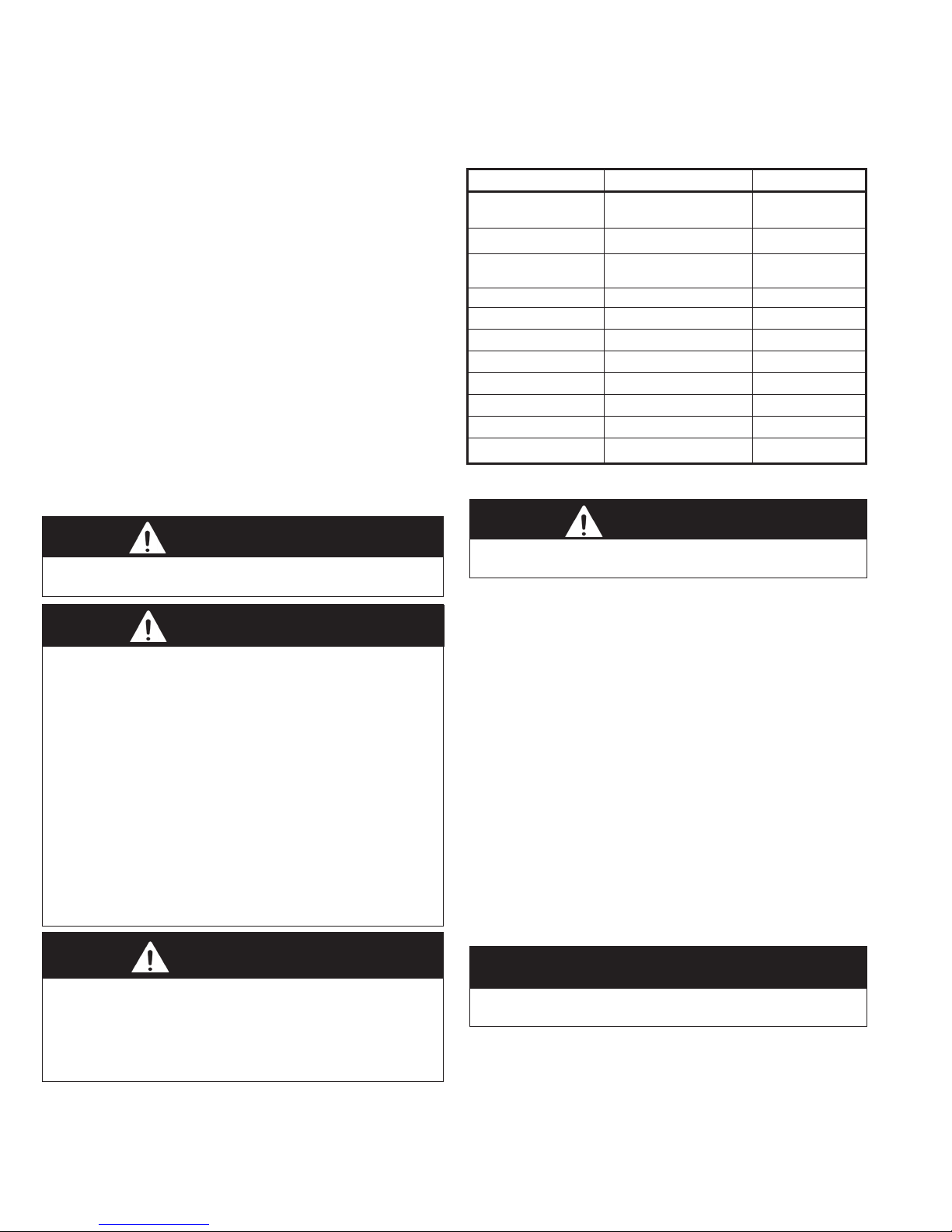
Table 2.1
SI (METRIC) CONVERSION FACTORS
To Convert Multiply By To Obtain
"W.C.
(inches water column)
psig 6.893 kpa
inches 25.4 mm
feet 0.305 meters
CFM 0.028 m3/min
CFH 1.699 m3/min
btu/ft3 0.0374 mJ/m
pound 0.453 kg
btu/hr 0.000293 kW/hr
gallons 3.785 liters
°F
0.24 kPa
(°F-32) × 0.555
°C
3
UNIT LOCATION
DANGER
Units must not be installed where they may be exposed to a
potentially explosive or flammable atmosphere.
1. Units should not be installed in atmospheres where
corrosive fumes or sprays are present.
2. Be sure no obstructions block air intake or air discharge of
unit heater.
3. Columns, machinery, partitions, and other obstacles should
not interfere with air streams from unit heaters.
4. Unit heaters installed in a building exposed to a prevailing
wind should be located to direct a major volume of heated
air along the windward wall of the building.
5. Vertical delivery unit heaters should generally be located in
the central area of the space to be heated. Place horizontal
delivery units along the walls of the same building where
heat loss is usually greatest.
6. Arrange horizontal delivery units so they do not blow
directly at occupants.
7. When only vertical delivery units are installed, they should
be located so exposed walls are blanketed by their air
streams.
8. Mounting height is critical for optimum performance. Refer
to Mounting Height on page 4 before installation.
CAUTION
1. Do not reuse any electrical component which has been
wet. Such component must be replaced.
2. Do not operate the units within steam pressure greater
than 10 psig. Steam pressure must be 10 psig. or lower
to avoid excessive discharge air temperatures that could
cause burns or personal injury.
2
IMPORTANT
Start-up and adjustment procedures must be performed by a
qualified service agency.
AIR11-500.6
INSTALLATION - UNIT MOUNTING / PIPING / ELECTRICAL CONNECTIONS
INSTALLATION
Unit Mounting
1. Open front panel and line up end compartment with roughedin piping and position unit at ceiling or wall location. (Hinged
cabinet doors may be removed to facilitate unit installation.)
2. Fasten floor or wall mounted unit to wall studs through
the four mounting holes in the back of the unit. For ceiling
mounted units sizes 002-006, suspend four 1/4" threaded
hanger studs from ceiling joists to match mounting holes in
back of unit and fasten with lockwashers and hex nuts. (For
sizes 008-014, use a 3/8" threaded rod.)
Perma-Lap® Frames
A Perma-Lap® frame (see Figure 11.3 on page 10) provides
a finished appearance to a recessed wall or ceiling cabinet
unit heater. The installation is easy and assures a perfect fit
by neatly framing the heater and covering any irregularities
between the heater and the opening in the wall or ceiling.
Because the bond between wall or ceiling surfaces and the
Perma-Lap® framing is permanent, there is no opportunity for
air leakage which can cause wall streaking.
Since the enclosure front panel is never in contact with the wall
or ceiling, servicing the heater involves simply removing the
heater front panel and leaving the Perma-Lap® and cabinet
enclosure permanently fixed in the recess opening.
Perma-Lap® frames allow flexibility in recessing depth. Enclosures
may be flush, recessed or partially recessed. Desired unit projection
on partially recessed units is accomplished by positioning the unit
within the Perma-Lap® frame. The four sided Perma-Lap® frame
has a 3/8” projection and a 1 ½” width.
Piping
CAUTION
CAUTION
Failure to wire this unit according to this wiring diagram may
result in injury to the installer or user. For deviations, contact
the factory.
1. Installation of wiring must conform with local building
codes, or in the absence of local codes, with the National
Electric Code ANSI/NFPA 70 - Latest Edition. Unit must
be electrically grounded in conformance to this code. In
Canada, wiring must comply with CSA C22.1, Electrical
Code.
2. Electric wiring must be sized to carry the full load amp draw
of the motor and any controls that are used with the unit
heater. Overcurrent protectors should be sized based on
motor current rating shown on the unit serial plate, and
applicable national electric code procedures.
All units are provided with an electrical junction box. Make
wiring connections from 115V/60Hz/1Ø building service to
control box as shown on wiring diagram furnished with the
unit.
Any damage to or failure of Modine units caused by
incorrect wiring of the units is not covered by Modine’s
standard warranty.
3. Location of room thermostat, when supplied, should be in
the natural circulating path of room air. Mount thermostat
about five feet above floor level where it will not be affected
by heat from the unit or other sources of drafts that would
prevent it from properly controlling room temperature. See
instructions packed with the thermostat.
4. With ceiling mounted units, a multi-speed remote fan
switch is supplied as standard. The switch can be recessed
into a standard 2 x 4 electrical wall box.
1. Do not reuse any electrical component which has been
wet. Such component must be replaced.
2. Do not operate the units within steam pressure greater
than 10 psig. Steam pressure must be 10 psig. or lower
to avoid excessive discharge air temperatures that could
cause burns or personal injury.
1. On standard coil (single row), connections are 3/4" MPT on
unit sizes 002 through 006.
On high capacity coil (2 row), connections are 5/8" ID sweat
on unit sizes 002 through 006. On high capacity coil (3 & 4
row), connections are 3/4" NPT on unit sizes 002 through 006.
On unit sizes 008 through 014, either standard or high capacity
coil, connections are 1" NPT. On high capacity coil (3 & 4 row),
connections are 1" NPT on unit sizes 008 through 014.
2. Supply and return lines should be adequately sized to handle
heating requirements under maximum load.
3. Attach air vent fitting at the high point of the piping in the unit
on hot water systems.
4. Install piping to provide for expansion and contraction
normally encountered with temperature changes.
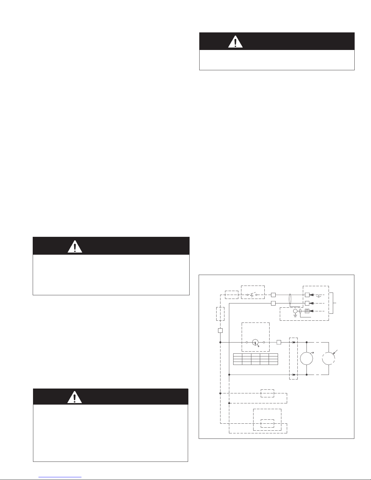
Electrical Connections
WARNING
1. Disconnect power supply before making wiring connections
to prevent electrical shock and equipment damage.
2. All appliances must be wired strictly in accordance with
wiring diagram furnished with the appliance. Any wiring
different from the wiring diagram could result in a hazard to
persons and property.
3. Any original factory wiring that requires replacement must
be replaced with wiring material having a temperature
rating of at least 105°C.
Figure 3.1
Standard Wiring Diagram for Cabinet Unit Heaters
AIR11-500.6
ACCESSORY
MOTOR
STARTER
ACCESSORY
3
AQUASTAT
Motor Type
PSC
Shaded Pole
High Static
Return Air Option or
Rated Amps
Factory Installed
FIELD INSTALLED
THERMOSTAT
MOUNT INSIDE J-BOX
SPEED
CONTROL
Ground
See Below Motor Key For Motor
Information and Wiring Configuration
Terminal 4
Terminal 3
BLK
2.5 A
5.0 A RED
BLK WHT
10.0 A
FIELD INSTALLED
CONTROL VALVE
(ACCESSORY OR
BY OTHERS)
Motorized Damper Option or
FIELD INSTALLED
MOTORIZED DAMPER
(ACCESSORY)
1
2
Ground
WHT
N / A
RED
GRN
N / A
Factory Installed Disconnect Option or
16 AWG
MAIN
GROUND
OPTIONAL MOTOR PLUG
AND SOCKET CONNECTIONS
4
16 AWG
WHT
F1
BLK
FIELD INSTALLED
DISCONNECT
L1
L2
WHT
F2
BLK
115V / 60HZ /
1PH POWER
CIRCUIT
BREAKER
BY OTHERS
REQUIRED FOR
SIZES 008 - 014
3
INSTALLATION - MOUNTING HEIGHT / OPERATION
Mounting Height
Height at which cabinet unit heaters are installed is critical.
Maximum mounting heights for all units are listed in the tables
below. The data in tables are based on operating conditions of 2
lbs. steam or 220°F entering water with 60°F entering air. When
operating conditions are other than those above, refer to chart
for mounting height correction factor. To obtain the maximum
mounting height at actual operating conditions, multiply the
appropriate factor from chart by the mounting height in Tables.
The mounting heights must be followed closely to assure
maximum comfort.
Strong opposing drafts, large obstructions in the air stream of
the unit, and higher than normal discharge air temperatures
(resulting from high steam pressures) can prevent the heated air
discharged by the cabinet unit from reaching the floor.
Under unfavorable conditions such as these, allowances must be
made to assure maintenance of desired comfort.
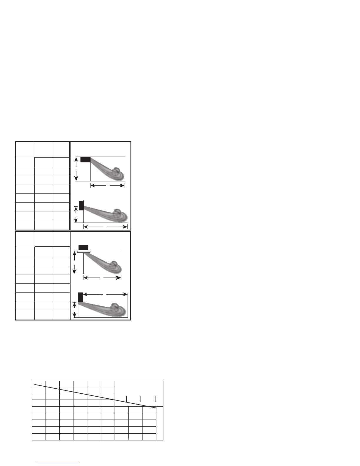
Table / Figure 4.1 - Maximum Mounting Height
Size H T
(Ft.) (Ft.)
002 8 15
003 8 18
004 9 22
006 9 23
008 10 26
010 10 27
012 11 26
014 11 27
Size H T
(Ft.) (Ft.)
Standard Air Flow
Ceiling-Mounted
H
T
Inverted Air Flow
Wall-Mounted
H
T
Standard Air Flow
Ceiling-Mounted
OPERATION
1. Make sure fuses are installed in fused disconnect switches.
2. Check all electrical connections to assure they are secure.
3. Check rigidity of unit mounting. Tighten all fasteners,
if necessary.
4. Inspect piping, strainers, traps, fittings, etc.
Initial Start-Up
1. Set thermostat to lowest position.
2. Turn on power supply to unit.
3. Open return gate valve, and then open supply gate valve
to unit.
4. Raise thermostat setting to desired position.
5. Adjust louvers (if provided) for desired heat distribution.
6. To insure proper sequence of operation, cycle unit on and
off a few times by raising and lowering thermostat setting.
7. Check for proper rotation of fan. See dimensional drawings
on page 8 or 9 for indication of fan rotation.
Automatic Control Operations
Install one of the following operating systems for continuous
automatic control.
Intermittent Fan Operation — Hot Coil
A room thermostat starts and stops the fan motor. An aquastat
is sometimes strapped to the return piping to prevent fan
operation when heat is not being supplied to the unit heater.
Continuous Fan Operation — Intermittent Hot/Cold
Coil
A room thermostat controls a valve which opens to allow steam
or hot water to supply the unit and closes to shut off the supply
when the thermostat is satisfied.
002 7 8
003 8 10
004 8 11
006 8 12
008 10 16
010 10 18
012 11 20
014 11 21
➀ Maximum mounting height and corresponding heat throw of heaters operating
at standard conditions (2 lbs. steam or 220°F entering water, 60° entering air).
H
T
Inverted Air Flow
Wall-Mounted
T
H
Table 4.2
Maximum Mounting Heights Correction Factors
These correction factors are to be used as multipliers to correct
the maximum recommended mounting heights “H” or heat
throw “T” of cabinet unit heaters when operated with steam
pressures other than 2 pounds or with water at other than
entering temperature of 220°F.
1.3
1.2
1.1
1.0
.9
.8
.7
.6
.5
CORRECTION FACTOR “R”
150° 160° 170° 180° 190° 200° 210° 220° 230° 240°
4
AVERAGE WATER TEMP. (°F)
Steam Pressure
2 5
10
AIR11-500.6
 Loading...