

Modine Manufacturing Lodronic HCH Service Manual
1-660.0
5H0827900000
– ACCESSORY DOWNWARD DEFLECTOR HOOD
IMPORTANT
1. The use of this manual is specifically intended for a
qualified installation and service agency. All installation
and service of these kits must be performed by a
qualified installation and service agency.
2. These instructions must also be used in conjunction
with the Installation and Service Manual originally
shipped with the appliance, in addition to any other
accompanying component supplier literature.
August, 2019
INSTALLATION INSTRUCTIONS
30°, 60°, and 90° downward deflector hoods
LodronicTM Models HCH
Deflector Hood Model Application
The 30°, 60° and 90°, Downward Deflector Hoods are
designed for use on Lodronic
Assembly/Installation
The recommended procedure for assembly and installation
is described as follows:
Before beginning installation of the accessory hood,
remove all of the spring loaded louver blades from the
unit heater on which the hood is to be installed. These
blades will be relocated in the face of the hood
assembly after the hood assembly is complete (except
90° hoods). Not all blades from the unit heater will be
used on the hood, but all should be removed prior to
installing the hood. For 90° hoods, separate louvers will
ship with the hood assembly. To remove the spring
loaded louver blades, grasp the blade and apply
pressure against the louver blade retaining spring. After
compressing the spring, the tab on the opposite side of
the blade can be removed from the unit, freeing the
blade from the unit.
Note: Do not lose the louver blade retaining springs as they
will be required later to install the blades into the hood
assembly.
TM
hydronic unit heaters.
THIS MANUAL IS THE PROPERTY OF THE OWNER.
PLEASE BE SURE TO LEAVE IT WITH THE OWNER WHEN YOU LEAVE THE JOB.
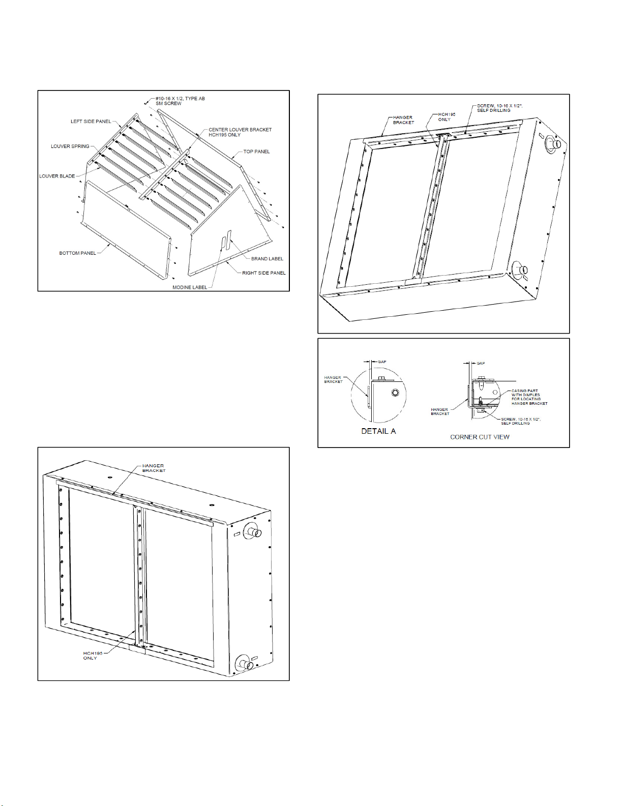
Figure 2.1 - Hood Exploded View
1. Install the hood hangar bracket to the top interior surface
of the unit opening (see figure 2.2), using the #10 x ½”
self drilling screws provided. Dimples located at the top
of the opening will provide locating points to secure the
bracket. Once the bracket is installed, ensure that there
is a small gap between the hangar bracket and the front
face of the unit. A screwdriver or similar tool may be
required if adjustment needs to take place to create a
gap.
Figure 2.2 – Hanger Bracket
2. Hood assembly is generally easiest if done with the
surfaces of the hood panels with flanges facing the floor.
Begin the hood assembly by positioning the hood bottom
so that the flanges are on the outside of a side panel.
Attach the bottom panel to the side panel of the hood
using the #10 x 1/2" sheet metal screws through the
provided holes. Repeat for the other side panel
3. Position the hood top so that the flanges are on the
outside of the side panels. Secure the hood to the side
panels using the #10 x 1/2" sheet metal screws through
the provided holes
4. Complete the hood frame by using the #10 x 1/2" sheet
metal screws through provided holes on the outlet
surface of the hood. Install the center louver channel if
provided.
5. Install the louvers taken from the unit (or provided with
the kit for 90° hoods). Take the louver springs used on
the unit, and place them over the tab of the louver.
Press the tab into the hood panel dimple, compressing
the spring. Slide the tab on the other end of the louver
into the dimple.
6. Provided Modine and Lodronic labels can be placed as
desired on the exterior of the hood.
1-660.0
 Loading...