

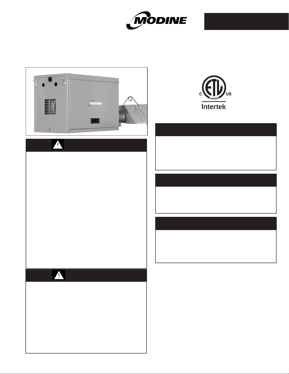
INSTALLATION AND SERVICE MANUAL
low intensity gas-red pressurized infrared heaters
WARNING
1. Improper installation, adjustment,
alteration, service or maintenance can
cause property damage, injury or death,
and could cause exposure to substances
which have been determined by various
state agencies to cause cancer, birth
defects, or other reproductive harm. Read
the installation, operating, and
maintenance instructions thoroughly
before installing or servicing this
equipment.
2. Do not locate ANY gas-fired units in areas
where chlorinated, halogenated, or acidic
vapors are present in the atmosphere.
These substances can cause premature
heat exchanger failure due to corrosion
which can cause property damage, serious
injury or death.
3. For either indoor or outdoor installation.
Not for use in residential dwellings.
CAUTION
As with all infrared equipment, clearances to
combustible materials are critical. Be sure all
units have reflectors installed along the
entire length of the tube, and that they are not
mounted at an angle greater than 45° from
the horizontal plane. In locations used for
storage of combustible materials, signs shall
be clearly posted in the vicinity of the heater
where readily apparent to material handlers
to specify the maximum permissible stacking
height to maintain required clearances from the
heater to the combustibles.
9-511.4
5H0819050000
February, 2019
model IPT
FOR YOUR SAFETY
IF YOU SMELL GAS:
1. Open windows (indoor installation only).
2. Do not touch electrical switches.
3. Extinguish any open flame.
4. Immediately call your gas supplier.
FOR YOUR SAFETY
The use and storage of gasoline or other
flammable vapors and liquids in open
containers in the vicinity of this unit is
hazardous.
IMPORTANT
The use of this manual is specifically intended
for a qualified installation and service agency.
A qualified installation and service agency
must perform all installation and service of
these appliances.
Inspection upon Arrival
1. Inspect unit upon arrival. In case of damage, report it
immediately to transportation company and your local Modine
Sales Representative.
2. Check rating plate on unit to verify that power supply
meets available electric power at the point of installation.
3. Inspect unit upon arrival for conformance with description of
product ordered (including specifications where applicable).
THIS MANUAL IS THE PROPERTY OF THE OWNER.
PLEASE BE SURE TO LEAVE IT WITH THE OWNER WHEN YOU LEAVE THE JOB.
SPECIAL PRECAUTIONS
SPECIAL PRECAUTIONS
THE INSTALLATION AND MAINTENANCE INSTRUCTIONS IN
THIS MANUAL MUST BE FOLLOWED TO PROVIDE SAFE,
EFFICIENT AND TROUBLE-FREE OPERATION. IN ADDITION,
PARTICULAR CARE MUST BE EXERCISED REGARDING
THE SPECIAL PRECAUTIONS LISTED BELOW. FAILURE
TO PROPERLY ADDRESS THESE CRITICAL AREAS COULD
RESULT IN PROPERTY DAMAGE OR LOSS, PERSONAL
INJURY, OR DEATH. THESE INSTRUCTIONS ARE SUBJECT
TO ANY MORE RESTRICTIVE LOCAL OR NATIONAL CODES.
HAZARD INTENSITY LEVELS
1. DANGER: Indicates an imminently hazardous situation
which, if not avoided, WILL result in death or serious injury.
2. WARNING: Indicates a potentially hazardous situation which,
if not avoided, COULD result in death or serious injury.
3. CAUTION: Indicates a potentially hazardous situation which,
if not avoided, MAY result in minor or moderate injury.
4. IMPORTANT: Indicates a situation which, if not avoided,
MAY result in a potential safety concern.
DANGER
Appliances must not be installed where they may be
exposed to a potentially explosive or flammable atmosphere.
WARNING
10. Disconnect power supply before making wiring connections
to prevent electrical shock and equipment damage.
11. All appliances must be wired strictly in accordance with
the wiring diagram furnished with the unit. Any wiring
different from the wiring diagram could result in a hazard
to persons and property.
12. Any original factory wiring that requires replacement
must be replaced with wiring material having a
temperature rating of at least 105°C.
13. Ensure that the supply voltage to the appliance, as
indicated on the serial plate, is not 5% greater than rated
voltage.
14. When servicing or repairing this equipment, use only
factory-approved service replacement parts. A complete
replacement parts list may be obtained by contacting
Modine Manufacturing Company. Refer to the rating
plate on the unit for complete unit model number, serial
number, and company address. Any substitution of parts
or controls not approved by the factory will be at owner’s
risk.
CAUTION
WARNING
1. Do not locate ANY gas-fired units in areas where
chlorinated, halogenated, or acidic vapors are present in
the atmosphere. These substances can cause premature
heat exchanger failure due to corrosion which can cause
property damage, serious injury or death.
2. To prevent risk of fire or improper unit operation, radiant
tube baffle must be properly selected from Table 10.1
according to fuel type, burner input, and tube system length
and it must also be properly assembled and installed.
3. To prevent tube sections from separating during unit
operation, tube clamps must be centered over the joints
of adjoining tube sections and tightened to 50 ft. - lb. and
the clamp fastened to the tubes using (2) self-tapping
screws. Failure to do so may result in separation of tube
sections which could fall and result in death or serious injury.
4. All field gas piping must be pressure/leak tested prior to
operation. Never use an open flame. Use a soap solution
or equivalent for testing.
5. Gas pressure to appliance controls must never exceed
14" W.C. (1/2 psi).
6. Do not join two sections of Type B double wall vent pipe
within the vent system. A compromised pipe joint/liner pipe
may or not be detected, resulting in serious injury or
death.
7. A built-in combustion air blower is provided – additional
external draft hoods (diverters) or power exhausters are
not required or permitted.
8. To reduce the opportunity for condensation, the minimum
sea level input to the appliance, as indicated on the serial
plate, must not be less than 5% below the rated input.
9. A certified flexible connector must be used (local codes
permitting) as a the method of connecting the heaters to
the gas supply to avoid placing stress on the gas supply
line due to the expansion of the low intensity infrared
tubes during operation.
1. As with all infrared equipment, clearances to combustible
materials are critical. Be sure all units have reflectors
installed along the entire length of the tube, and that they
are not mounted at an angle greater than 45° from the
horizontal plane. In locations used for storage of
combustible materials, signs shall be clearly posted in the
vicinity of the heater where readily apparent to material
handlers to specify the maximum permissible stacking
height to maintain required clearances from the heater to
the combustibles.
2. Installation must conform with local building codes or in
the absence of local codes, with Part 7, Venting of
Equipment, or the National Fuel Gas Code, ANSI Z223.1
(NFPA 54) – latest edition. In Canada installation must be
in accordance with CAN/CGA-B149.1 for natural gas
units, and CAN/CGA-B149.2 for propane units.
3. Purging of air from gas lines should be performed as
described in ANSI Z223.1 – latest edition "National Fuel
Gas Code" or in Canada in CAN/CGA-B149 codes.
4. When leak testing the gas supply piping system, the
appliance and its combination gas control must be
isolated during any pressure testing in excess of 14" W.C.
(1/2 psi).
5. The unit should be isolated from the gas supply piping
system by closing its field installed manual shut-off valve.
This manual shut-off valve should be located within 6' of
the heater.
6. Turn off all gas before installing appliance.
7. Ensure that the supply voltage to the appliance, as
indicated on the serial plate, is not 5% less than the rated
voltage.
8. Do not attempt to reuse any mechanical or electrical
controllers which have been wet. Replace defective
controller.
2
9-511.4
SI (METRIC) CONVERSION FACTORS/UNIT LOCATION
Table 3.1 - SI (Metric) Conversion Factors
IMPORTANT
1. Approval requirements for infrared heaters specify that
the suspended type heaters shall be installed in
accordance with certain sections of the National Fire
Codes published by the National Fire Protection
Association and various ANSI standards. SOME of the
requirements are listed below.
Aircraft Hangars: Approval requirements are contained
in the current edition of ANSI/NFPA 409 (or in
accordance with the enforcing authority for Canada).
Public Garages: Approval requirements are contained in
the current edition of NFPA 88B (CAN/CGA B149 for
Canada).
Parking Structures: Approval requirements are
contained in the current edition of NFPA 88A.
General: All installations must be in accordance with the
current edition of ANSI Z-223.1 (NFPA 54) National Fuel
Gas Code and the current edition of the National Electric
Code, ANSI/NFPA 70. For Canada, installations must
conform with local building codes, or in the absence of
local codes, in accordance with the current edition of
CAN/CGA B149 and the Canadian Electric Code, C22.1.
2. Start-up and adjustment procedures should be performed
by a qualified service agency.
3. To check most of the Possible Remedies in the
troubleshooting guide listed in Table 23.1, refer to the
applicable sections of the manual.
To Convert Multiply By To Obtain
"W.C. 0.249 kPa
°F (°F-32) x 5/9 °C
Btu 1.06 kJ
Btu/ft3 37.3 kJ/m
Btu/hr 0.000293 kW
CFH (ft3/hr) 0.000472 m3/min
CFH (ft3/hr) 0.00000787 m3/s
CFM (ft3/min) 0.0283 m3/min
CFM (ft3/min) 0.000472 m3/s
UNIT LOCATION
Appliances must not be installed where they may be
exposed to a potentially explosive or flammable atmosphere.
Do not locate ANY gas-fired units in areas where chlorinated,
halogenated, or acidic vapors are present in the atmosphere.
These substances can cause premature heat exchanger
failure due to corrosion which can cause property damage,
serious injury or death.
To Convert Multiply By To Obtain
feet 0.305 m
Gal/Hr. 0.00379 m3/hr
Gal/Hr. 3.79 l/hr
3
gallons 3.79 l
Horsepower 746 W
inches 25.4 mm
pound 0.454 kg
psig 6.89 kPa
psig 27.7 "W.C.
DANGER
WARNING
Table of Contents
General Information/Installation Codes ...................1
Inspection upon Arrival ................................1
Special Precautions ..................................2
SI (Metric) Conversion Factors .........................3
Unit Location........................................4
Location Recommendations ........................4
Combustion Air Requirements ..........................4
Ventilation Air Requirements ........................4
Clearances to Combustibles ........................4
Installation .........................................5
Pre-Installation Notes .............................5
Removal of Burner Side Access Panels ...............5
Rotation of Gas Valve .............................5
Straight Tube Components .........................6
U-Tube Components..............................7
Unit Mounting – Tube System.......................8
UnitMounting–TurbulatorBafe ...................10
Unit Mounting – Burner ...........................10
UnitMounting–Reector .........................11
Additional Recommendations for Outdoor Installation ...11
Venting .......................................12
Gas Connections................................15
High-Altitude Accessory Kit ........................16
Electrical Connections............................18
Start-Up Procedure..................................19
Main Burner Adjustment ..........................19
Primary Air Shutter(Propane Only) ..................19
Control Operating Sequence ......................19
Dimensional Data ...................................20
Performance.......................................21
Maintenance.......................................22
Service & Troubleshooting . . . . . . . . . . . . . . . . . . . . . . . . . . . .23
Replacement Parts Ordering ..........................24
Model Number Designations ..........................24
Serial Number Designations...........................24
Wiring Diagram..................................25,26
Warranty..........................................28
9-511.4
CAUTION
As with all infrared equipment, clearances to combustible
materials are critical. Be sure all units have reflectors
installed along the entire length of the tube, and that they are
not mounted at an angle greater than 45° from the horizontal
plane. In locations used for storage of combustible materials,
signs, shall be clearly posted in the vicinity of the heater
where readily apparent to material handlers to specify the
maximum permissible stacking height to maintain required
clearances from the heater to the combustibles.
IMPORTANT
Approval requirements for infrared heaters specify that the
suspended type heaters shall be installed in accordance
with certain sections of the National Fire Codes published
by the National Fire Protection Association and various
ANSI standards. SOME of the requirements are listed
below.
Aircraft Hangars: Approval requirements are contained in
the current edition of ANSI/NFPA 409 (or in accordance with
the enforcing authority for Canada).
Public Garages: Approval requirements are contained in
the current edition of NFPA 88B (CAN/CGA B149 for
Canada).
Parking Structures: Approval requirements are contained
in the current edition of NFPA 88A.
General: All installations must be in accordance with the
current edition of ANSI Z-223.1 (NFPA 54) National Fuel
Gas Code and the current edition of the National Electric
Code, ANSI/NFPA 70. For Canada, installations must
conform with local building codes, or in the absence of local
codes, in accordance with the current edition of CAN/CGA
B149 and the Canadian Electric Code, C22.1.
3
UNIT LOCATION /AIR REQUIREMENTS
"B"
"C"
"A"
0° MOUNTING ANGLE
"B"
"C"
"C"
CHAIN LOCATION
45° MOUNTING ANGLE
(MAXIMUM)
"A"
Location Recommendations
1. When locating the heater, consider the general space and
heating requirements and availability of gas and electrical
supply.
2. Be sure the structural support and chain at the unit location is
adequate to support the weight of the unit.
3. Be sure that the minimum clearances to combustible
materials and are maintained. The minimum clearances to
combustibles are shown in Table 4.1, and Figures 4.1 and
4.2, as well as affixed to the burner Model Identification plate.
4. Maintain a recommended minimum of 18" clearance from the
access side of the burner box and also on the combustion air
inlet end of the burner box.
5. Mounting height (measured from the bottom of unit) at which
heaters are installed is important to maintain proper occupant
comfort levels. Please refer to mounting height information in
Table 21.1.
6. Do not locate units in areas where chlorinated, halogenated,
or acid vapors are present in the atmosphere.
7. Unit gas control can be field configured for right or left access,
depending on unit location. See general instructions for
"Rotation of Gas Control" on page 5.
Combustion Air Requirements
Units installed in tightly sealed buildings or confined spaces
must be provided with two permanent openings, one near the
top of the confined space and one near the bottom. Each
opening should have a free area of not less than one square
inch per 1,000 BTU per hour of the total input rating off all units
in the enclosure, freely communicating with interior areas
having, in turn adequate infiltration from the outside.
For further details on supplying combustion air to a confined
(tightly sealed) space or unconfined space, see the National
Fuel Gas Code ANSI Z223.1 of CAN/CGA B149.1 or .2
Installation Code, latest edition.
An accessory combustion air intake collar can be used to bring
outside combustion air to the unit using 4" pipe. Refer to the
venting section "Utilizing Outside Combustion Air" on page 14
for details on pipe length and location.
Clearance to Combustibles
Ensure that:
1. Clearances to combustibles (as shown on the Model
Identification plate and in Table 4.1) are maintained. These
Clearances also apply to vehicles parked below the heater.
2. Adequate clearances to sprinkler heads are maintained. As a
guideline, certified minimum distance to combustible material
is based on the combustible material surface not exceeding
90˚Faboveambient(160˚Ftypical).
3. The stated clearance to combustibles represents a surface
temperature of 90°F (50°C) above room temperature.
Building materials with a low heat tolerance (such as plastics,
vinyl siding, canvas, tri-ply, etc.) may be subject to
degradation at lower temperatures. It is the installer's
responsibility to assure that adjacent materials are protected
from degradation.
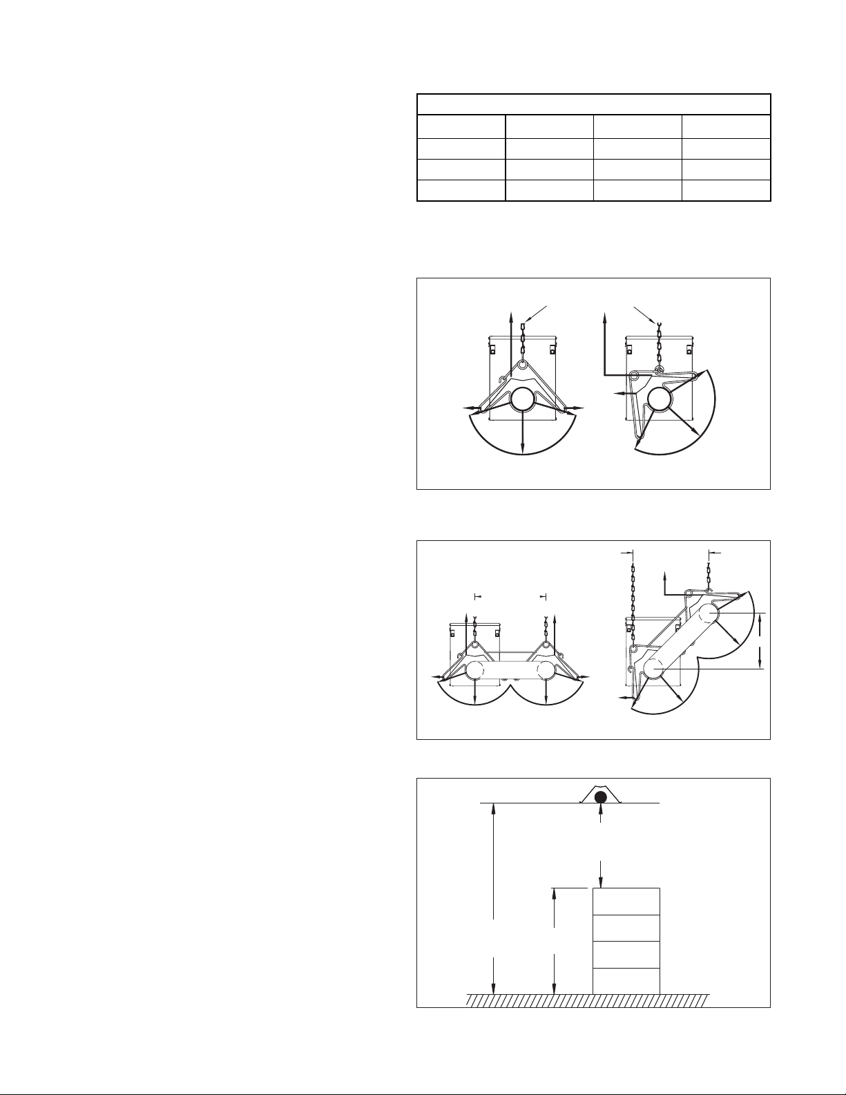
Storage of Combustible Materials
In locations used for storage of combustible materials, signs
shall be clearly posted in the vicinity of the heater where readily
apparent to material handlers to specify the maximum
permissible stacking height to maintain required clearances from
the heater to the combustibles. See Figure 4.3.
Table 4.1 - Combustible Material Clearances (inches) ➀
Combustible Material Clearances (inches)
Input MBH “A” ➀ “B” “C”
50/60 9 54 20
75/100/125 9 76 24
150/175/200 12 106 38
➀ Clearance to each end and above the U-Tube is 12 inches.
Refer to Figures 4.1 and 4.2.
Figure 4.1 - Combustible Material Clearances Straight Tube
CHAIN LOCATION
"A"
"C"
"B"
0° MOUNTING ANGLE
"A"
"C"
"C"
"B"
45° MOUNTING ANGLE
(MAXIMUM)
Figure 4.2 - Combustible Material Clearances -
U-Tube
CHAIN LOCATION
"A"
"C"
CHAIN LOCATION
"A"
"B"
"U" TUBE
0° MOUNTING ANGLE
"B"
"A"
"C"
"C"
"B"
"B"
"U" TUBE
45° MOUNTING ANGLE
(MAXIMUM)
12"
Figure 4.3 - Stacking Height
Minimum Clearance to
Combustible Materials
Unit Heater
Mounting
Height
Stacking
Height
4
9-511.4
INSTALLATION
Unit Mounting – Pre-Installation Notes
WARNING
1. To prevent risk of fire or improper unit operation, radiant
tube baffle must be properly selected from Table 10.1
according to fuel type, burner input, and tube system
length and it must also be properly assembled and installed.
2. To prevent tube sections from separating during unit
operation, tube clamps must be centered over the joints
of adjoining tube sections and tightened to 50 ft. - lb. and
the clamp fastened to the tubes using (2) self-tapping
screws. Failure to do so may result in separation of tube
sections which could fall and result in death or serious injury.
1. Be sure the method of unit suspension is adequate to support
the weight of the burner and tube system (see Tables 18.1
and 18.2 for system weights).
2. Combustible material and service clearances as specified in
Table 4.1 and Figures 4.1 through 4.3 must be strictly
maintained.
3. Maintain a recommended minimum of 18" clearance from the
access side of the burner box and also on the combustion air
inlet end of the burner box.
4. Before installing, review the components to be installed
against Figure 6.1 and Table 6.1 for straight tube systems or
Figure 7.1 and Table 7.1 for U-Tube systems. Ensure that all
parts are identified and available before proceeding with
installation of the unit.
5. It is recommended that the uninstalled system components
be arranged on the floor, where possible, to match the
intended layout. This can help ensure the layout matches the
intended design.
6. The standard gas control access is on the left side when
looking at the back end of the burner (combustion air inlet
end). If the intended installation requires access from the
opposite side, please follow the instructions in the section
titled "Rotation of Gas Control" prior to burner installation.
7. For proper operation, the burner and tube system must be
installed in a level horizontal position. Use a spirit level during
installation to ensure that the unit is suspended level.
8. Under no circumstances should the gas supply line or the
electrical supply line to the heater provide any assistance in
the suspension of the heater. Do not locate any gas or
electric service line directly above or below the heater.
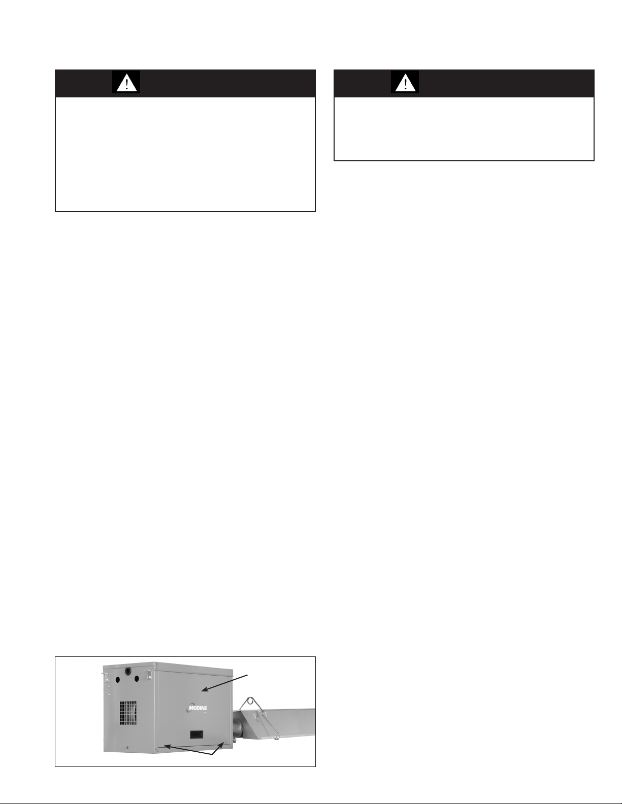
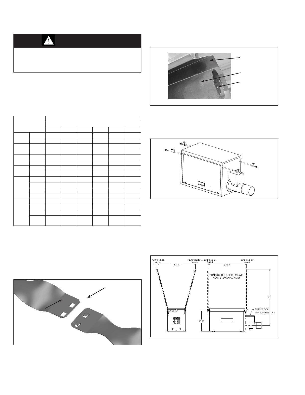
Removal of Burner Side Access Panels
Each of the two side access panels are held in place by two (2)
screws, as shown in Figure 5.1. Once the screws are removed,
the panels slide down, where they can either hang on the
hooks shown in Figure 22.1 or be removed completely during
service or maintenance. The unit is designed to operate without
these panels in place so that adjustments of the controls can
be made. The panels must be returned to the unit once
installation is complete.
Figure 5.1 - Side Access Panels
Rotation of Gas Control
WARNING
1. All field gas piping must be pressure/leak tested prior to
operation. Never use an open flame. Use a soap solution
or equivalent for testing.
2. Gas pressure to appliance controls must never exceed
14" W.C. (1/2 psi).
This section is only required if opposite side gas control access
is required. The standard access is on the left side when looking
at the back of the burner box (combustion air inlet end).
In order to install the heater so that the gas valve's controls can
be accessed from the opposite side of the burner box, the valve
may be rotated 180° by following the procedure below.
1. Remove burner side access panels as described in the
previous section.
2. Unplug all wires from the valve.
3. Using two wrenches, loosen the factory-supplied union in
the burner box and remove the gas valve. Do not apply
the wrenches directly to either the gas valve or the
gas manifold.
4. Remove the plug from the factory-supplied "tee" fitting and
screw it into the opposite leg of the tee. Be sure to properly
seal the threads of this connection.
5. Seat the gas valve onto the factory-supplied union, so that
the valve faces the opposite side of the burner box.
Tighten the union using two wrenches, without applying
them directly to either the gas valve or the gas manifold.
6. Plug-in all wires removed from the valve in step 2.
7. The gas piping/fitting connections must be pressure/leak
tested as outlined in the section titled "Gas Connections"
on page 15.
8. Replace the burner side access panels.
Remove Screws (2)
Side Access
Panel
9-511.4
5
INSTALLATION
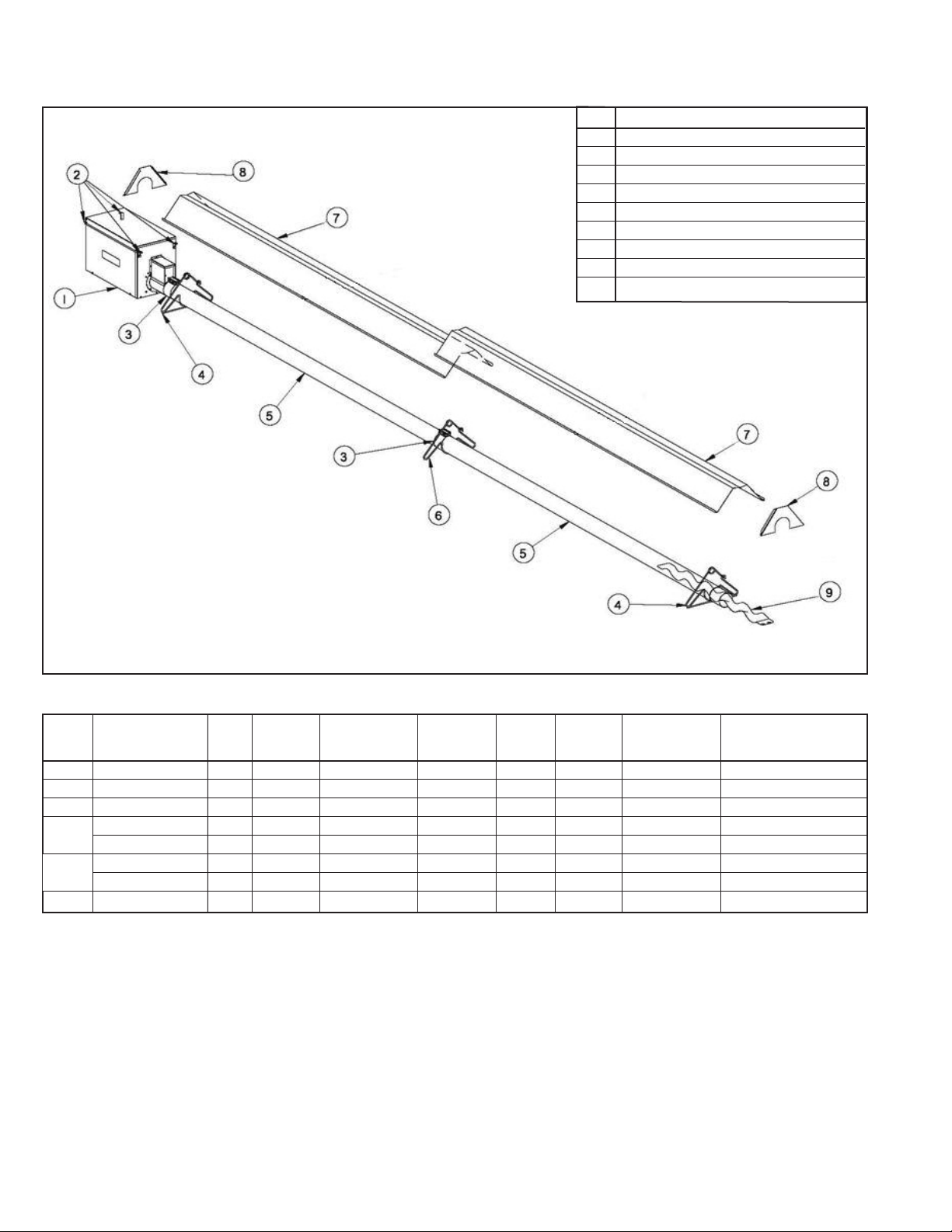
Figure 6.1 - Straight Tube System Components
Ref # Part Description
1 Burner
2 Burner Support Bracket (Qty. 4)
3 Tube Clamp
4 Tube&ReectorHangerw/ReinforcingBar
5 Radiant Tube
6 Tube&ReectorHanger
7 Reector
8 ReectorEndCap
9 TurbulatorBafe
Table 6.1 - Straight Tube System Component List
Tube Single-Tube Single-Tube Stocking Kit
Length Available Burner 10' 10' Hangers with Hangers Tube Reector Turbulator Option Requires the
(ft.) Input MBH Tubes Reectors Reinforcing Bar (regular) Clamps End Cap Bafe Sections Following Tube Kits ➁:
20 50, 60, 75 2 2 2 1 3 2 4 A
30 50, 60, 75, 100 3 3 2 2 4 2 4 E
40 60, 75, 100, 125 4 4 2 3 5 ➀ 2 4 A + D
50 100, 125 5 5 2 4 6 ➀ 2 4 E + D
50
150, 175, 200 5 ➀ 5 2 4 6 ➀ 2 4 B + C
60 125 - 1-Stage Only 6 6 2 5 7 ➀ 2 4 A + D + D
60
60 150, 175, 200 6 ➀ 6 2 5 7 ➀ 2 4 B + D
70 175, 200 7 ➀ 7 2 6 8 ➀ 2 4 B + E
➀ Tube systems for input ratings of 150MBH and higher utilize a 409 Aluminized Stainless Steel First tube section with stainless steel tube clamps.
➁ Tube systems can be ordered as either Modular (complete system) or Stocking Kits (combination of kits to form complete system).
6
9-511.4
INSTALLATION
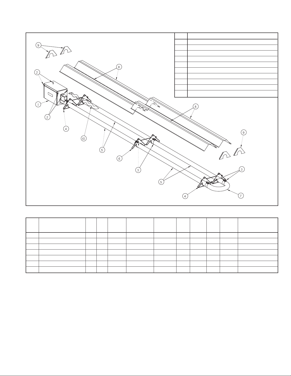
Figure 7.1 - U-Tube System Components
Ref # Part Description
1 Burner
2 Burner Support Bracket (Qty. 4)
3 Tube Clamp
4 DoubleTube&ReectorHangerw/ReinforcingBar
5 Radiant Tube
6 DoubleTube&ReectorHanger
7 U-Tube
8 Reector
9 ReectorEndCap
10 TurbulatorBafe
Table 7.1 - U-Tube System Component List
Tube Double-Tube Double-Tube Turbulator Stocking Kit
Length Available Burner 5' 10' 10' Hangers with Hangers Tube Reector Bafe Option Requires the
(ft.) Input MBH Tubes Tubes Reectors Reinforcing Bar (regular) Clamps End Cap U-Tube Sections ➂ Following Tube Kits ➁
20 50, 60, 75 - 2 2 2 - 4 4 1 4 A + U-Tube
30 50, 60, 75, 100 2 2 4 2 1 6 4 1 4 N/A
40 60, 75, 100, 125 - 4 4 2 1 6 4 1 4 A + D + U-Tube
50 100, 125, 150, 175, 200 2 4 ➀ 6 2 2 8 ➀ 4 1 4 N/A
60 125 - 1-Stage Only - 6 6 2 2 8 4 1 4 A + D + D + U-Tube
60 150, 175, 200 - 6 ➀ 6 2 2 8 ➀ 4 1 4 B + D + U-Tube
70 175, 200 2 6 ➀ 8 2 3 10 ➀ 4 1 4 N/A
➀ Tube systems for input ratings of 150MBH and higher utilize a 409 Aluminized Stainless Steel First tube section with stainless steel tube clamps.
➁ Tube systems can be ordered as either Modular (complete system) or Stocking Kits (combination of kits to form complete system).
➂ Forinstallationswhere4bafesareneedonstraighttubesetups,U-tubeinstallationswillonlyrequire3bafes.
9-511.4
7
INSTALLATION
Unit Mounting – Tube System
WARNING
To prevent tube sections from separating during unit
operation, tube clamps must be centered over the joints of
adjoining tube sections and tightened to 50 ft. - lb. and the
clamp fastened to the tubes using (2) self-tapping screws.
Failure to do so may result in separation of tube sections
which could fall and result in death or serious injury.
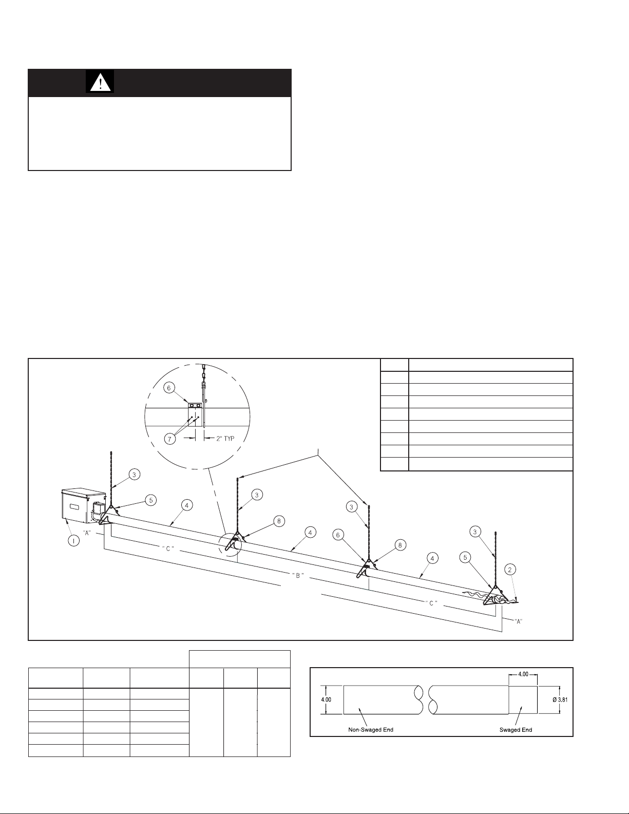
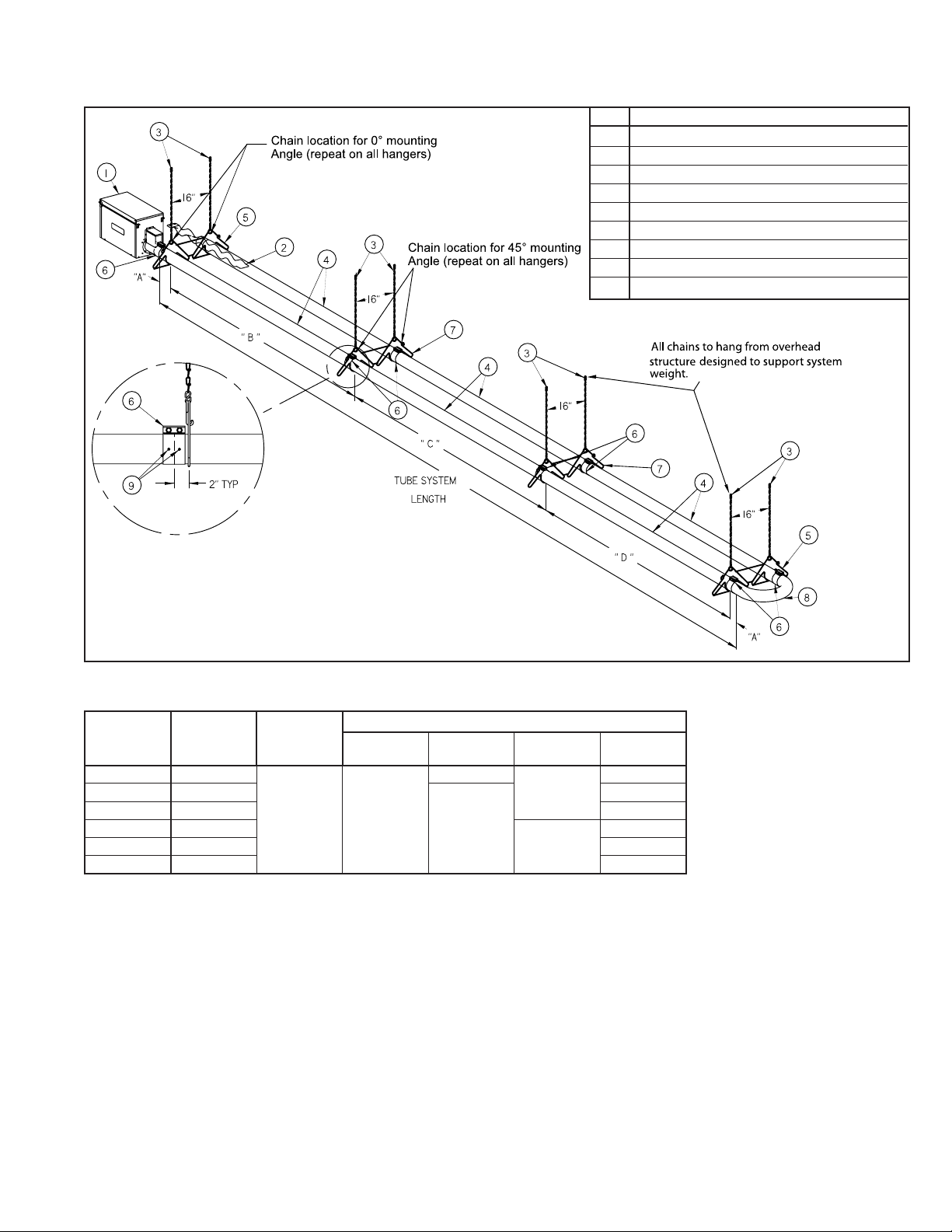
For steps 1-8 of this section, please refer to Figures 8.1 and 9.1
1. Locate and install tube and reflector system hanging chains
(200 lb. minimum working load) as shown, following spacing
indicated in Table 8.1 or 9.1.
2. Fasten tube and reflector hangers to the hanging chains
installed in the previous step using ¼" diameter S-Hooks (70
lb. minimum working load). The hangers must be positioned
so that the tube system to be installed will be in the horizontal
plane and level. Refer to Figures 8.1 and 9.1 for chain
location on tube systems mounted at a 45° angle. Also note
that the first and last hangers are to be the type with
reinforcing bar. Do not close ends until the tube system
installed in subsequent steps is confirmed to be level.
3. Identify the first burner tube and first and second tube clamps
as follows:
Figure 8.1 - Straight Tube System Suspension
All chains to hang from
overhead structure designed
to support system weight.
• For units under 150,000 Btu/hr, all tubes and clamps
are the same.
• For units 150,000 Btu/hr and over, the first tube is
shinier than the other tubes and is stenciled with the
words “First Tube”. The first two tube clamps have a
shiny, mirror-like appearance.
4. Loosely slide the second tube clamp approximately 6" past
the swaged end (see Figure 8.2 for identification of tube ends).
5. Starting from the end of the tube system where the burner will
be installed (done in later steps), slide the first burner tube
through the first and second tube hangers. The non-swaged
end is to go through the first tube hanger and the swaged end
is to go through the second tube hanger. Position the tube so
the welded seam is directed toward the floor.
6. Loosely slide the next tube clamp over the swaged end of the
next tube and slide the non-swaged end over the swaged end
of the preceding tube, ensuring that the welded seam on the
tube is directed toward the floor. The other end is to be
inserted through the following tube hanger.
7. Center the tube clamp on the preceding tube over the joint of
the two tubes as shown in Figures 8.1 or 9.1 and tighten the
tube clamp bolts to 50 ft.-lb. Secure the tube clamp to both
tubes using (2) self-tapping sheet metal screws.
8. Repeat steps 6 and 7 until all tube sections are installed.
9. Verify that the tube system is level. If the tube is not level,
adjust the position of the hanger on the hanging chain. Once
level, crimp the ends of the S-hooks on the hangers closed.
Ref # Part Description
1 Burner (Installed In Later Steps)
2 TurbulatorBafe
3 Chain & “S” Hooks
4 Radiant Tube
5 Tube&ReectorHangerw/ReinforcingBar
6 Tube Clamp
7 Self-Tapping Sheet Metal Screws
8 Tube&ReectorHanger
TUBE SYSTEM
LENGTH
Table 8.1 -
Straight Tube Chain Spacing
Tube System Number of Minimum "A" "B" "C"
Length (ft) Chains Chain Length ➀ ➁ ➂
20 3 18"
30 4 18"
40 5 18"
50 6 18"
60 7 24"
70 8 24"
➀"A"Dimensionisspacingfromthetubesystemendstotherstandlasthangers.
➁ "B" Dimension is spacing between hangers for tubes between "C" dimensions.
➂"C"Dimensionisspacingbetweenthersttwohangersandthelast2hangers.
Chain to Chain
Spacing Dimensions
N/A
6"
9' 8"
9' 4"
8
Figure 8.2 - Tube Ends (Dimensions in inches)
9-511.4
INSTALLATION
Figure 9.1 - U-Tube System Suspension
Ref # Part Description
1 Burner (installed In later steps)
2 Turbulator Baffle
3 Chain & “S” Hooks
4 Radiant Tube
5 DBL Tube & Reflector Hanger w/ Reinforcing Bar
6 Tube Clamp
7 Double Tube & Reflector Hanger
8 U-Tube
9 Self-Tapping Sheet Metal Screws
Table 9.1 - U-Tube Chain Spacing
Tube System
Length (ft)
20 4
30 6
40 6 4' 4"
50 8
60 8 4' 4"
70 10 4' 4"
➀ “A” Dimension is spacing from the tube system ends to the first hanger and from the U-tube ends to the last hanger.
➁ “B” Dimension is spacing between first and second hangers away from burner.
➂ “C” Dimension is spacing between hangers for tubes between “B” and “D” dimensions.
➃ “D” Dimension is spacing between first and second hangers away from U-tube.
Number of
Chains
Maximum
Chain
Length
18" 6"
"A"
Dimension ①
Espacement des chaînes
"B"
Dimension ②
N/A
9' 4"
"C"
Dimension ③
N/A
9' 8"
"D"
Dimension ④
Sans objet
4' 4"
4' 4"
9-511.4
9
INSTALLATION
Unit Mounting – Turbulator Baffle
WARNING
To prevent risk of fire or improper unit operation, radiant
tube baffle must be properly selected from Table 10.1
according to fuel type, burner input, and tube system length
and it must also be properly assembled and installed.
1. The last section of radiant tube is to include a turbulator baffle
assembly. Determine the quantity of baffle sections to be
installed based on the burner rating and tube system length,
per Table10.1. Discard any baffle sections that will not be
required for the assembly.
Table 10.1 - Turbulator Baffle Assembly Section Qty.
Determination
Bafe Quantity
Input MBH
20 30 40 50 60 70
NG 2 2 - - - -
50
60
75
100
125
150
175
200
* Max. tube length on 125MBH 2-Stage units is 50'
* Note - Tube lengths shown are for units installed at elevations of 0-2001'.
Allowable tube lengths may differ upon elevation changes.
* Note - Forinstallationswhere4bafesareneedon straighttubesetups,
U-tubeinstallationswillonlyrequire3bafes.
2. Assemble the turbulator baffle assembly by mating the
LP 1 1 - - - -
NG 3 1 0 - - -
LP 3 1 0 - - -
NG 4 2 2 - - -
LP 4 2 - - - -
NG - 4 3 2 - -
LP - 4 3 - - -
NG - - 3 2 2 -
LP - - 4 3 1 -
NG - - - 3 2 -
LP - - - 3 2 -
NG - - - 3 2 2
LP - - - 3 2 0
NG - - - 4 2 0
LP - - - 4 2 0
sections determined in the previous step as shown in
Figure 10.1.
Tube Length (ft)
3. Insert the completed turbulator baffle assembly into the last
radiant tube, flush with the end as shown in Figure 10.2.
Figure 10.2 - Insertion of Turbulator Baffle Assembly
Reflector
Last Tube
Baffle
Unit Mounting – Burner
1. Install four burner support brackets as shown in Figure 10.3
with the bolts supplied.
Figure 10.3 - Burner Support Bracket Installation
2. The burner must be suspended with four chains (200 lb.
minimum working load) to allow for system expansion and
contraction during unit operation, as shown in Figure 10.4.
Note that for U-tube systems mounted at a 45° angle, the
exiting side of the tube system is 12" higher than the burner
(see Figure 4.2). Locate and mount burner to ensure that
Clearance to Combustibles are maintained (refer to
"Clearance to Combustibles" on page 4).
Figure 10.4 - Burner Suspension
Figure 10.1 - Assembly of Turbulator Baffle Assembly
Tabs
Slots
10
9-511.4
INSTALLATION
Unit Mounting – Radiant Reflector
CAUTION
As with all infrared equipment, clearances to combustible
materials are critical. Be sure all units have reflectors
installed along the entire length of the tube, and that they are
not mounted at an angle greater than 45° from the horizontal
plane. In locations used for storage of combustible materials,
signs, shall be clearly posted in the vicinity of the heater
where readily apparent to material handlers to specify the
maximum permissible stacking height to maintain required
clearances from the heater to the combustibles.
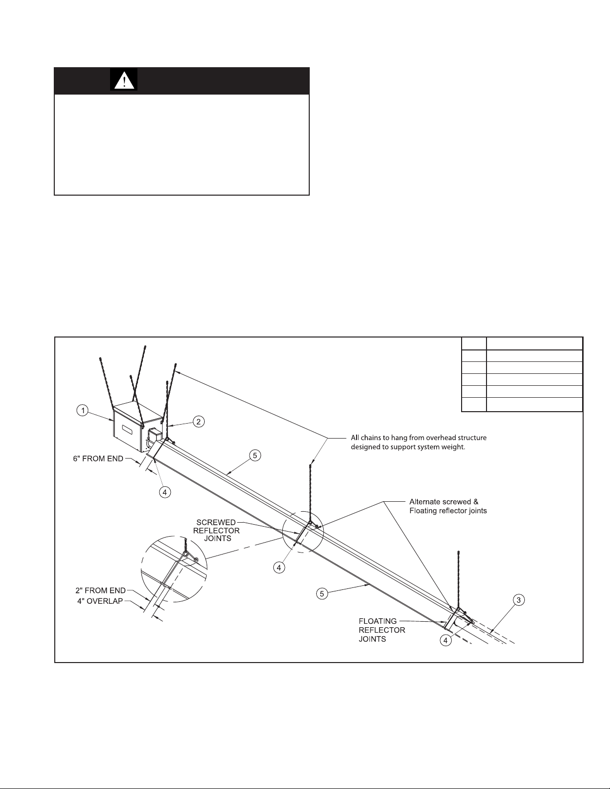
For steps 1-7, refer to Figure 11.1.
1. The entire radiant tube length must have radiant reflector
installed. The only exception is that on U-tube systems, a
reflector is not installed over the U-tube.
2. Remove any protective plastic covering the reflectors.
3. Starting from the burner, slide a reflector through the tube and
reflector hangers and position the reflector so that it is
centered over the tube. The end closest to the burner should
be 6" from the first tube and reflector hanger.
Figure 11.1 - Installation of the Radiant Reflectors
4. Slide the next reflector through the tube and reflector hangers
and center over the next tube. The reflector should overlap
the previous reflector by 4". Repeat until all reflectors are
installed (alternating top and bottom overlaps).
5. Starting from the burner end and working toward the vent end
of the tube system, overlapping reflector joints are to be either
secured or remain unsecured as follows:
• Every odd numbered reflector to even numbered
reflector joint (reflectors 1 to 2, 3 to 4, etc.) is to be
secured with self-tapping sheet metal screws.
• Every even numbered reflector to odd numbered
reflector joint (reflectors 2 to 3, 4 to 5, etc.) is to remain
unsecured to allow for expansion and contraction during
operation.
6. Reflector end caps are to be fastened to both ends of the
reflector system using sheet metal screws.
Additional Recommendations for Outdoor Installation
Complies with Canadian Standard CAN1-2.21
When utilized in an outdoor installation or in aircraft hangars, the
following is required:
1. A screened combustion air intake cap.
2. All electrical connections must be water tight and suitable for
outdoor use.
Ref # Part Description
1 Burner
2 Chain & “S” Hooks
3 Radiant Tube
4 Tube&ReectorHanger
5 Reector
9-511.4
11
INSTALLATION
Venting
WARNING
1. A built-in combustion air blower is provided – additional
external draft hoods (diverters) or power exhausters are
not required or permitted.
CAUTION
Installation must conform with local building codes or in the
absence of local codes, with Part 7, Venting of Equipment, or
the National Fuel Gas Code, ANSI Z223.1 (NFPA 54) – latest
edition. In Canada installation must be in accordance with
CAN/CGA-B149.1 for natural gas units, and CAN/
CGA-B149.2 for propane units.
General Venting Instructions
The vent pipe may be installed in either a vertical or horizontal
method. Certified vent pipe lengths are as follows:
Table 12.1 - Maximum Vent Length
Input MBH
50, 60, 75, 100
125 30' 30'
150, 175, 200 40' 30'
Min Vent
Lenght (ft.)
5'
Maximum Vent Length (ft.)
1-Stage 2-Stage
20' 20'
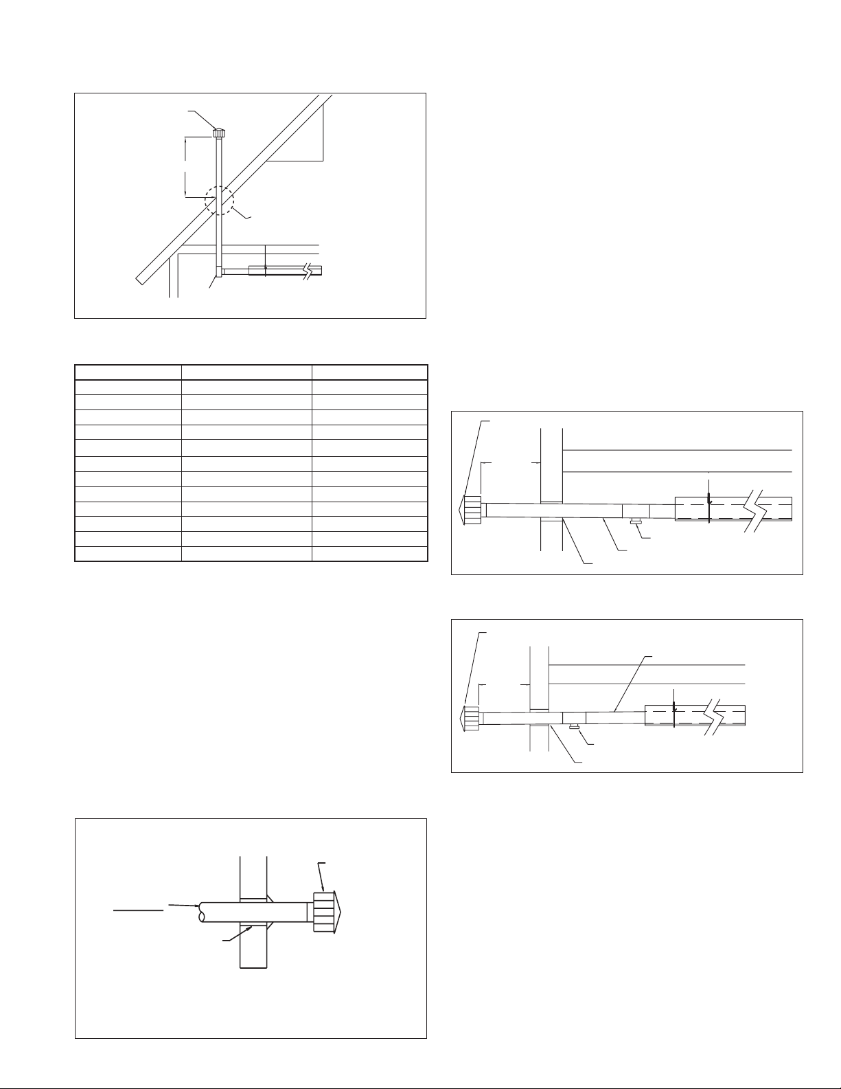
Figure 12.2 - Vertical Venting
2' Min.
Approved cap
1' Min.*
See Figure 12.2
Drip Leg
Downward slope 1/4" towards drip leg.
* Size according to expected snow depth.
Figure 12.3 - Construction through Combustible Roof
1. All systems are considered a Category III appliance and the
vent system must be approved for Category III application in
accordance with UL1738 or ULCS636.
2. Use either a certified Category III vent system with a
maximum flue temperature of up to 550°F, or single wall vent
pipe with all joints (fastened with 3 corrosion resistant sheet
metal screws) and seams sealed with a 550°F or greater
sealant. Follow the vent manufacturers instructions for
clearance to combustibles.
3. Refer to the National Fuel Gas Code for the minimum
material thickness and composition of the vent material.
4. If single wall vent systems are used, Type B vent can be used
to terminate the vent system. The Type B double wall vent
must be one continuous section. Under no circumstances
should two sections of double wall vent pipe be joined
together within one vent system due to the inability to verify
complete seal at inner pipes.
5. All seams and joints must be inspected to ensure gas
tightness after installation. Vent system (connections, joints,
and seems) must be leak checked using a soap solution
6. Models 50-75 use 3" venting. Models 100-200 use 4". For
models 50-75, a 4" to 3" reducer must be used to connect the
last tube section to the 3" vent pipe. It is recommended that
vent pipes be fitted with a tee with a drip leg and a clean out
cap to prevent any moisture in the vent pipe from entering the
unit. The drip leg should be inspected and cleaned out
periodically during the heating season See figure 13.1 & 13.3.
7. The National Fuel Gas Code requires a minimum clearance
of 6 inches from combustible materials for single wall vent
pipe. The minimum distance from combustible materials is
based on the combustible material surface not exceeding
160°F. Clearance from the vent pipe (or the top of the unit)
may be required to be greater than 6 inches if heat damage
other than fire (such as material distortion or discoloration)
could result.
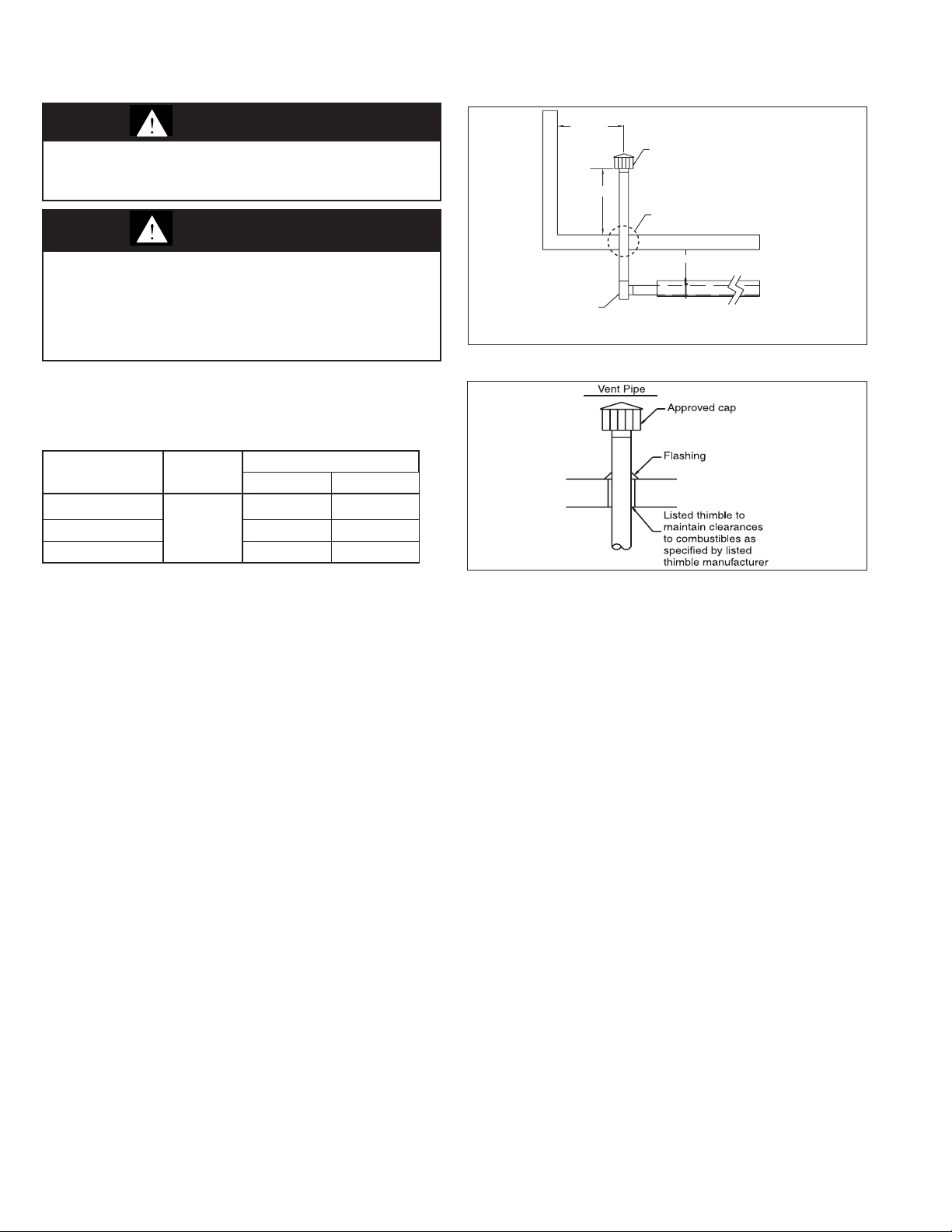
8. Avoid venting through unheated space when possible. When
single wall pipe does pass through an unheated space, insulate
runs greater than 5' to minimize condensation. Inspect for
leakage prior to insulating and use insulation that is
noncombustible with a rating of not less than 550°F. Install a
tee fitting at the low point of the vent system and provide a drip
leg with a clean out cap as shown in Figure 12.2. The drip leg
should be cleaned annually.
9. Where the vent passes through a combustible wall or floor or
ceiling, a listed metal thimble 4" greater than the vent
diameter is necessary. If there are six feet or more of vertical
vent pipe in the open space between the unit heater and
where the vent pipe passes through the floor or roof, the
thimble need only be 2" greater than the diameter of the vent
pipe. If a thimble is not used, all combustible material must be
cut away to provide a 6 inch clearance. Any material used to
close an opening must be noncombustible. Vent pipes must
be adequately supported and sealed with a 550°F or greater
sealant.
10. The vent termial must be Modine part number:
- 5H0722850005 (item code 27865) 3" vent pipe
- 5H0722850001 (item code 27866) 4" vent pipe
11. Do NOT vent this appliance into a masonry chimney.
12. Do NOT use dampers or other devices in the vent pipes.
13. Do NOT use PVC pipe.
14. Precautions must be taken to prevent degradation of
building materials by flue products.
15. The top of the vertical stack should extend at least 2' above
any portion of a building within a horizontal distance of 2'.
16. For pitched roof vertical venting, refer to Figure 13.1 and
Table 13.1 for the vertical distance that the cap must extend
above the pitched roof.
17. Common venting is not allowed for Category III appliances.
12
9-511.4
INSTALLATION
A
Listed thimble
to maintain
clearances as
specified by
listed thimble
manufacturer
Vent Pipe
vent terminal
Figure 13.1 - Vertical Venting through Sloped Roof
pproved Cap
Roof Pitch
x
is x/12
H
Drip Leg
Downward slope 1/4" towards drip leg.
12"
See Figure 12.2
Table 13.1 - Minimum Height from Roof to Lowest
Discharge Opening
Rise X (inches) Roof Pitch
0-6 Flat to 6/12 1
6-7 6/12 to 7/12 1.25
7-8 7/12 to 8/12 1.50
8-9 8/12 to 9/12 2
9-10 9/12 to 10/12 2.50
10-11 10/12 to 11/12 3.25
11-12 11/12 to 12/12 4
12-14 12/12 to 14/12 5
14-16 14/12 to 16/12 6
16-18 16/12 to 18/12 7
18-20 18/12 to 20/12 7.50
20-21 20/12 to 21/12 8
* Size according to expected snow depth.
MIn. Height (ft)*
Additional Requirements for Horizontal Venting
1. All horizontal termial must be Modine part number:
- 5H0722850005 (item code 27865) 3" vent pipe
- 5H0722850001 (item code 27866) 4" vent pipe
In the United States, the vent cap must be 24" from wall,
while in Canada, a distance of 48" from the wall is required.
2. When horizontal vents pass through a combustible wall (up to
8 inches thick), use a thimble with 2" clearances to the vent
and insulate between thimble and vent. The vent passage
may also be constructed and insulated as shown in Figure
13.2. Where horizontal vents pass through a non-combustible
wall, no clearances to the wall are required.
3. The vent system shall terminate at least 3' above any forced
air inlet (except direct vent units) located within 10', and at
least 4' below, 4' horizontally from, or 1' above any door,
window or gravity air inlet into any building. The bottom of the
vent terminal shall be located above the snow line or at least
1' above grade; whichever is greater. When located adjacent
to public walkways the vent system shall terminate not less
than 7' above grade.
4. Vent must extend beyond any combustible overhang of the
building.
5. The vent system shall not terminate over public walkways,
building entrances, or where condensate or vapor could
cause a nuisance or hazard or could be detrimental to the
operation of regulators, relief openings, or other equipment.
6. Precautions must be taken to prevent degradation of building
materials by flue products.
7. When vented horizontally, maintain a 1/4" per foot rise away
from the heater. Place a drain tee and clean out near the vent
connector (see Figure 13.3). Where local authorities have
jurisdiction, a 1/4" downward slope is acceptable. Use a drain
tee with a clean out near the exit of the vent (see Figure 13.4)
or allow the condensate to drip out the end.
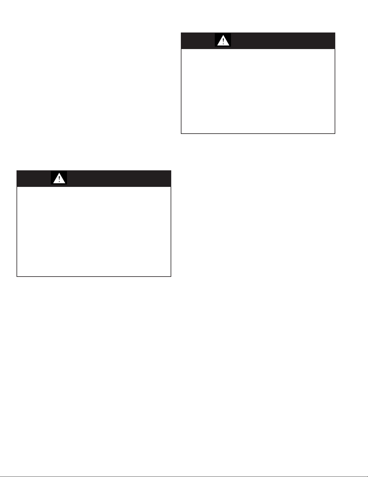
Figure 13.3 - Horizontal Venting with Upward Pitch
vent terminal
24" min.
(48" min.
in Canada)
Clean out/drip leg
1/4" Slope up towards termination
Listed thimble
Figure 13.4 = Horizontal Venting w/Downward Pitch
(with drip leg)
vent terminal
1/4" Slope down towards termination
24" min.
(48" min.
in Canada)
Tee with drip leg and cleanout cap at low
point of vent system
Listed Thimble
Figure 13.2 - Vent Construction through
Combustible Wall
9-511.4
13
INSTALLATION
Utilizing Outside Combustion Air (Optional)
1. An accessory combustion air intake collar is required for
connecting the combustion air piping to the burner box. For
outdoor installation, the air intake collar connects directly to
the accessory air intake cap.
2. All units may utilize a maximum of 20' of 4" O. D. fresh air
intake pipe with two (2) 90° elbows, 25' with one (1) elbow, or
30' with no elbows.
3. Modine recommends using 4" insulated (sealed) pipe or
Schedule 40 PVC pipe to provide fresh air and limit
condensation from forming on outer surface. A Modinespecified accessory screened combustion air intake cap is
required.
4. Insure that air intake cap is protected from snow blockage.
5. Keep intake opening at least 5 feet from any exhaust vent
opening.
6. Where practical, the outside combustion air intake is
recommended to be in the same pressure zone as the vent
termination.
Gas Connections
WARNING
1. All field gas piping must be pressure/leak tested prior to
operation. Never use an open flame. Use a soap solution
or equivalent for testing.
2. Gas pressure to the appliance controls must never exceed
14” W.C. (1/2 psi).
3. To reduce the opportunity for condensation, the minimum
sea level input to the appliance, as indicated on the serial
plate, must not be less than 5% below the rated input.
4. A certified flexible connector must be used (local codes
permitting) as the method of connecting the heaters to the
gas supply to avoid placing stress on the gas supply line
due to the expansion of the low intensity infrared tubes
during operation.
1. Installation of piping must conform with local building codes,
or in the absence of local codes, of the National Gas Fuel
Code, ANSI Z223.1 (NFPA 54) – Latest Edition. In Canada,
installation must be in accordance with CAN/CGA-B149.1 for
natural gas units and CAN/CGA-B149.2 for propane units.
2. Piping to units should conform with local and national
requirements for type and volume of gas handled, and
pressure drop allowed in the line. Refer to Table 19.1 to
determine the cubic feet per hour (cfh) for the type of gas and
size of unit to be installed. Using this cfh value and length of
pipe necessary, determine the pipe diameter from Table 19.1.
Where several units are served by the same main, the total
capacity, cfh, and length of main must be considered. Avoid
pipe sizes smaller than 1/2". Table 19.1 allows for a 0.3" W.C.
pressure drop in the supply pressure from the building main
to the unit. The inlet pressure to the unit must be 6" W.C. for
natural gas and 11-14" W.C. for propane gas. The gas supply
pressure must never exceed 14" W.C. If the pressure exceeds
14" W.C., a gas pressure regulator must be added upstream
of the combination gas valve. When sizing the inlet gas pipe
diameter, make sure that the unit supply pressure can be met
after the 0.3" W.C. has been subtracted. If the 0.3" W.C.
pressure drop is too high, refer to the Gas Engineer’s
Handbook for other gas pipe capacities.
CAUTION
1. Purging of air from gas supply line should be performed
as described in ANSI Z223.1 - latest edition “National Fuel
Gas Code”, or in Canada in CAN/CGA-B149 codes.
2. When leak testing the gas supply piping system, the
appliance and its combination gas control must be
isolated during any pressure testing in excess of 14" W.C.
(1/2 psi).
3. The unit should be isolated from the gas supply piping
system by closing its field installed manual shut-off
valve.This manual shut-off valve should be located within
6' of the heater.
4. Turn off all gas before installing appliance.
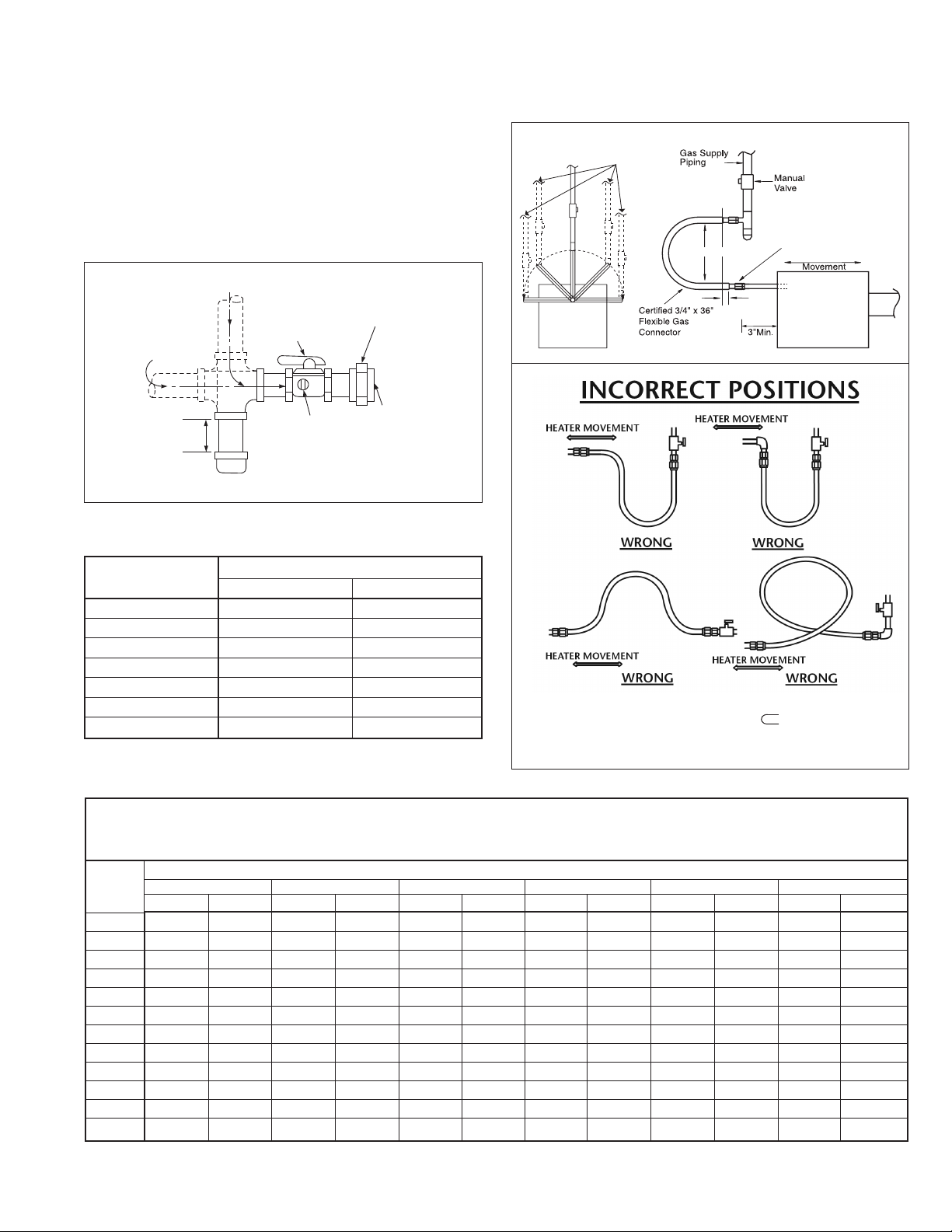
3. Install a ground joint union with brass seat and a manual
shutoff valve adjacent to the unit for emergency shut-off and
easy servicing of controls, including a 1/8" NPT plugged
tapping immediately upstream of the gas supply connection
to the heater, accessible for test gauge connection. See
Figure 15.1.
4. Provide a sediment trap before each unit and in the line
where low spots cannot be avoided. (See Figure 15.1).
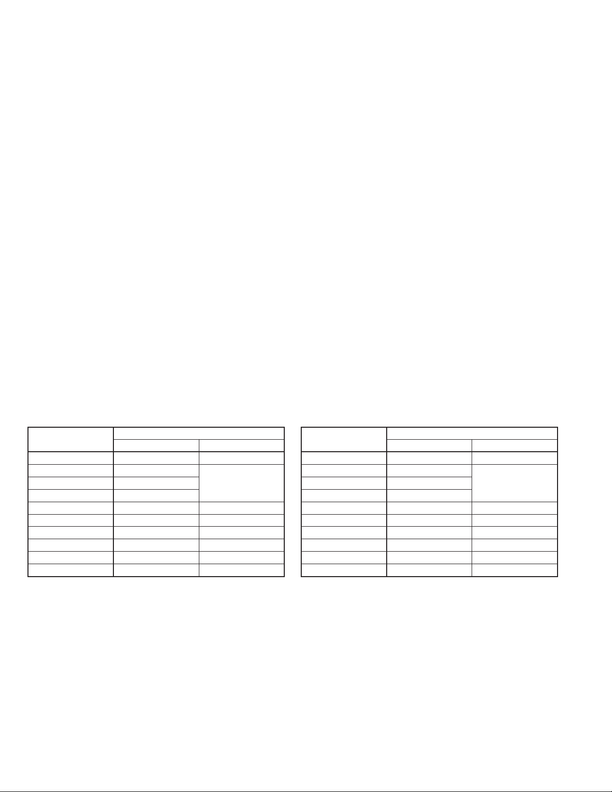
5. A certified, metallic stainless steel connector (local codes
permitting) of at least ¾” minimum ID by 36” long, must be used
as the method of connecting the heater to the gas supply line.
The connector must be certified to ANSI Z21.24/CSA 6.10. A
flexible connector avoids placing stress on the gas supply line
due to the thermal expansion of the unit while operating
Canadian installation codes do not permit the use of flexible
metallic connectors. In Canada, Installation Code CAN/
CSA-B149.1-05 requires the use of a Type I hose connector
certified to CSA CAN/CGA-8.1. Use a hose that is of the same
diameter and length as noted above. The certified flexible
connectors must be installed as illustrated in Figure 15.2, in one
plane, without any sharp bends, kinks, or twists. The gas
take-off from the drop line must be parallel to the burner gas
inlet connection.
6. Under no circumstances should the gas supply line to the
heater provide any assistance in the suspension of the
heater. Do not locate any gas service line directly above or
below the heater.
14
9-511.4
INSTALLATION
7. When pressure/leak testing pressures above
14" W.C. (1/2 psi), close the field installed shut-off valve,
disconnect the unit, and its combination gas control from the
gas supply line, and plug the supply line before testing. When
testing pressures 14" W.C. (1/2 psi) or below, close the
manual shut-off valve on the unit before testing.
8. If the gas valve was rotated to change control access side,
leak test fittings
Figure 15.1 - Recommended Sediment Trap/
Manual Shut-Off Valve Installation
SUPPLY LINE
Table 15.1 -
GAS
SUPPLY LINE
MANUAL GAS
TRAP
SHUT-OFF VALVE
PLUGGED
1/8" NPT TEST
GAGE CONNECTION
GAS
3"
MIN.
SEDIMENT
3/4" x 36" Flexible GasConnector Pressure
GROUND
JOINT
UNION
W/ BRASS
SEAT
TO
CONTROLS
Drop ("W.C.)
Input MBH
Natural Propane
50 0.03 0.02
60 0.04 0.02
75 0.05 0.03
100 0.08 0.04
150 0.14 0.07
175 0.18 0.09
200 0.23 0.11
Gas Type
Figure 15.2 - Recommended Installation of Flexible
Gas Connector
Alternate Supply Locations
should be maintained on a
12" radius arc
Field Supplied Gas Piping
Note: The gas supply nipple
must be parallel to the
12"
2"
Burner Box
(End View)
Warning:Connectormustbeinstalledinaconguration.Use
only a 36" long connector of 3/4" nominal ID with this heater. This is
offeredasafactorysupplied,eldinstalledaccessory.
heater movement.
Burner Box
(Side View)
Table 15.2 - Gas Pipe Capacities
Gas Pipe Capacities (Up to 14" W.C. Gas Pressure through Schedule 40 Pipe)
Cubic Feet per Hour with Pressure Drop of 0.3" W.C.
Natural Gas - Specific Gravity - 0.60
Propane Gas - Specific Gravity - 1.50
Length Pipe Diameter
Of Pipe 1/2" 3/4" 1" 1-1/4" 1-1/2" 2"
(feet) Natural Propane Natural Propane Natural Propane Natural Propane Natural Propane Natural Propane
10 132 83 278 175 520 328 1050 662 1600 1008 3050 1922
20 92 58 190 120 350 221 730 460 1100 693 2100 1323
30 73 46 152 96 285 180 590 372 890 561 1650 1040
40 63 40 130 82 245 154 500 315 760 479 1450 914
50 56 35 115 72 215 135 440 277 670 422 1270 800
60 50 32 105 66 195 123 400 252 610 384 1150 725
70 46 29 96 60 180 113 370 233 560 353 1050 662
80 43 27 90 57 170 107 350 221 530 334 990 624
90 40 25 84 53 160 101 320 202 490 309 930 586
100 38 24 79 50 150 95 305 192 460 290 870 548
125 34 21 72 45 130 82 275 173 410 258 780 491
150 31 20 64 40 120 76 250 158 380 239 710 447
9-511.4
15
INSTALLATION - HIGH ALTITUDE ACCESSORY KIT
HIGH ALTITUDE ACCESSORY KIT
Modine’s gas-fired equipment standard input ratings are
certified by ETL. For elevations above 2,000', ANSI Z223.1
requires ratings be reduced 4 percent for each 1000' above sea
level. For units in Canada, CSA requires that ratings be reduced
10 percent at elevations above 2,000'. The high altitude
adjustment instructions and pressure switch kits listed in this
manual are for use with units that will be installed over 2,000'
These methods and kits comply with both ANSI Z223.1 and
CSA requirements.
If a unit is to be installed at higher elevations AND converted from
natural gas to propane gas operation, a propane conversion kit
must be used in conjunction with the pressure adjustment
methods and pressure switch kits listed herein. For the Selection
and Installation Instructions for propane conversion kits, please
see the latest revision of Modine Manual 75-538.
Selection of the Proper Pressure and Kit
To determine the proper manifold pressure at altitude and if
required, the proper combustion air pressure switch kit, the full
model number of the heater, the fuel to be used, and the
altitude the unit will be installed at must be known. Refer to the
unit serial plate or carton label to obtain the necessary
information about the unit.
After obtaining this information, refer to the gas pressure and
selection charts shown in Tables 16.1 through 17.1. The
pressure charts are differentiated by elevation, fuel type, and
country the product is being installed in. The selection charts
are differentiated by product type, altitude and fuel type.
Selection charts include the proper kit suffix, when required.
Manifold Pressure Adjustment
The inlet pressure to the unit must be confirmed to be within
acceptable limits (6-7" W.C. for natural gas and 11-14" W.C.
for propane gas) before opening the shutoff valve or the
combination gas valve may be damaged.
Heaters for use with natural gas, the manifold pressure must
be set at 3.5” W.C. for high fire and 2.5" W.C. for low fire.
Units for use with propane gas, the manifold pressure must be
set at 10.0" W.C. for high fire and 6.2" W.C. for low fire.
Installation above 2,000'. elevation requires adjustment of the
manifold pressure as described.
Derated BTU Content Gas and Manifold Pressure
Calculation
Some utility companies may derate the BTU content (heating
value) of the gas provided at altitude to a value other than 1,050
BTU/ft3 for natural gas or 2,500 BTU/ft3 for propane gas to allow
certain heating appliances to be used with no manifold pressure
adjustments. For this reason it is necessary that the supplying
utility be contacted for detailed information about the gas type
and BTU content (heating value) before operating any heater.
Tables 16.1 and 16.2 show the standard derated heating values
(4% per 1,000' of elevation in the USA and 10% between 2,001’
and 4,500' elevation in Canada) of natural and propane gases
at various altitudes. If the utility is supplying gas with heating
values as shown in Tables 16.1 and 16.2, the manifold pressure
should be set to 3.5" W.C for natural gas and 10.0" W.C. for
propane gas.
NOTE: Both the high fire and low fire gas pressure must be
adjusted for proper operation.
Table 16.1 - Natural Gas Heating Values at
Altitude
Altitude (ft)
0-2,000 1,050 1,050
2,001-3,000 929
4,001-4,500 874
4,501-5,000 856 856
5,001-6,000 822 822
6,001-7,000 789 789
7,001-8,000 757 757
8,001-9,000 727 727
9,001-10,000 698 698
Values shown are for 3.5" W.C. manifold pressure, for other BTU content values (available from local utility) use Equation 17.1 to calculate manifold pressure.
Values shown are for 10.0" W.C. manifold pressure, for other BTU content values (available from local utility) use Equation 17.1 to calculate manifold pressure.
When installed at altitudes above 2,000', a pressure switch may need to be changed. Refer to Table 17.1 to determine if a switch change is required.
Gas heating values are derated 4% per 1,000' of elevation in the USA and 10% between 2,000' and 4,500' elevation in Canada in accordance with ANSI Z223.1
and CSA-B149, respectively.
Gas Heating Values at Altitude (BTU/ft3)
USA Canada
9453,001-4,000 892
Table 16.2 - Propane Gas Heating Values at
Altitude
Altitude (ft)
0-2,000 2,500 2,500
2,001-3,000 2,212
4,001-4,500 2,080
4,501-5,000 2,038 2,038
5,001-6,000 1,957 1,957
6,001-7,000 1,879 1,879
7,001-8,000 1,803 1,803
8,001-9,000 1,731 1,731
9,001-10,000 1,662 1,662
Gas Heating Values at Altitude (BTU/ft3)
USA Canada
2,2503,001-4,000 2,123
16
9-511.4
INSTALLATION - HIGH ALTITUDE ACCESSORY KIT
Table 17.1 - High Altitude Kits for IPT
Conversion IPT - Natural Gas 50 60 75 100 125 150 175 200
0-2000 FT 77823 77824
2001-3500 FT
3501-4000 FT
4001-4500 FT
4501-5000 FT
5001-5500 FT
5501-6000 FT
6001-6500 FT
6501-7500 FT
Conversion IPT - LP 50 60 75 100 125 150 175 200
0-2000 FT
2001-3500 FT
3501-4000 FT
4001-4500 FT
4501-5000 FT
5001-5500 FT
5501-6000 FT
6001-6500 FT
6501-7500 FT
77831
77836
77839
77847
77850
77832
77825
77834
77838
77840 77841 77842
77851
77854 77855
77837
77852 77853
77826 77827 77828 77829 77830
77843 77844 77845
77846
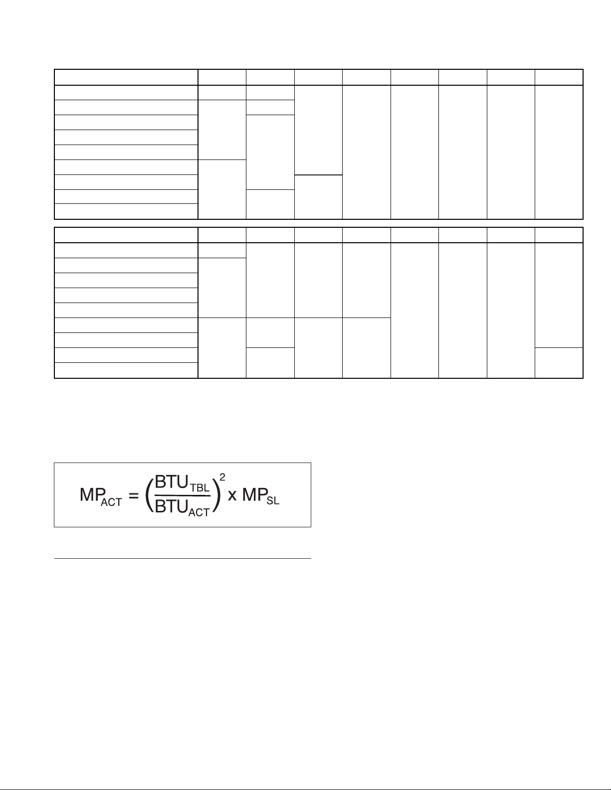
If the heating value of the gas being supplied is different than
the values shown in Tables 16.1 and 16.2, use the following
equation to determine the appropriate manifold pressure for the
altitude and gas heating value being supplied.
Equation 17.1 - Manifold Pressure for Derated Gas
WHERE:
M P
BTU
BTU
MPSL = Manifold Pressure (in. W.C.), at Sea Level –
NOTE: High and Low fire manifold pressure must both be
adjusted using the calculation shown in 17.1.
= Manifold Pressure (in. W.C.) at Altitude –
ACT
Manifold pressure setting for the heater
being installed
= BTU/ft3 Content of Gas –
TBL
Obtained from Tables 16.1 or 16.2
(whichever is applicable)
= BTU/ft3 Content of Gas –
ACT
Obtained from the local utility company
Use 3.5" W.C. for natural gas and 10.0" W.C. for
propane gas
9-511.4
17

INSTALLATION/START-UP PROCEDURE
Electrical Connections
WARNING
1. Disconnect power supply before making wiring connections
to prevent electrical shock and equipment damage.
2. All appliances must be wired strictly in accordance with
wiring diagram furnished with the appliance. Any wiring
different from the wiring diagram could result in a hazard
to persons and property.
3. Any original factory wiring that requires replacement must
be replaced with wiring material having a temperature
rating of at least 105°C.
4. Ensure that the supply voltage to the appliance, as indicated
on the serial plate, is not 5% greater than rated voltage.
CAUTION
Ensure that the supply voltage to the appliance, as indicated
on the serial plate, is not 5% less than the rated voltage.
1. Installation of wiring must conform with local building codes,
or in the absence of local codes, of the National Electric Code
ANSI/NFPA 70 - Latest Edition. Unit must be electrically
grounded in conformance to this code. In Canada, wiring
must comply with CSA C22.1 Part 1, Electrical Code.
2. Make sure all multi-voltage components (motors,
transform ers, etc.) are wired in accordance with the power
supply voltage.
3. The unit must be wired strictly in accordance with the wiring
diagram furnished with the unit.
4. The power supply to the unit should be protected with a fused
disconnect switch or circuit breaker.
5. The power supply must be within 5 percent of the voltage
rating and each phase must be balanced within 2 percent of
each other. If not, advise the utility company.
6. External electrical service connections that must be
installed include:
a. Supply power connection (120 volts).
b. Connection of thermostats, summer/winter switches, or
any other accessory control devices that may be supplied
(24 volts).
7. Control wire used to connect the heater to the thermostat
must have adequate ampacity and insulation temperature
rating for the total connected load, see Table 21.2.
8. Under no circumstances should the electrical supply or
control wiring to the heater provide any assistance in the
suspension of the heater. Do not locate any wiring directly
above or below the heater.
9. All outdoor electrical connections must be weatherized to
prevent moisture from entering the electrical compartment.
10. Ensure proper polarity of unit and power source.
11. Refer to the unit dimensional drawings on Figure 20.1 for
the electrical knockout locations.
START-UP PROCEDURE
CAUTION
Purging of air from gas lines should be performed as
described in ANSI Z223.1 - Latest Edition “National Fuel
Gas Code”, or in Canada, CAN/CGA-B149 codes.
IMPORTANT
Start-up and adjustment procedures should be performed
by a qualified service agency.
1. Turn off power to the unit at the disconnect switch. Check
that fuses or circuit breakers are in place and sized correctly.
Turn all hand gas valves to the “OFF” position.
2. Remove service access side burner access panel as outlined
on page 5 in section titled "Removal of Burner Side Access
Panels".
3. Check that the supply voltage matches the unit supply
voltage listed on the serial plate. Verify that all wiring is
secure and properly protected. Trace circuits to insure the
unit has been wired according to the wiring diagram.
4. If utilizing indoor air for combustion, ensure adequate
ventilation for intake of fresh air. Check to see that there are
no obstructions to the intake of the unit.
5. Perform a visual inspection of the unit to make sure no
damage has occurred during installation. Check reflectors to
ensure they are installed between 0° and 45° from the
horizontal plane.
6. Recheck the gas supply pressure. The inlet pressure to the
unit must be 6" W.C. for natural gas and 11-14" W.C. for
propane gas. The gas supply pressure must never exceed
14" W.C. If the pressure exceeds 14" W.C., a gas pressure
regulator must be added upstream of the combinations gas
valve.
7. Open the field installed manual shutoff valve and turn power
on to the unit.
8. Check to make sure that the main gas valve opens upon a
call for heat from the thermostat. Check the manifold gas
pressure (see main burner adjustment).
9. Check to insure that gas controls sequence properly (See
Control Operating Sequence).
During checkout procedure, use the following steps to
verify that the venting system is adequately sized:
1. Inspect the venting system for proper size and horizontal
pitch, as required in the National Fuel Gas Code ANSI
Z223.1 or CAN/CGA B149.1 or .2 Installation Code – latest
edition and these instructions. Determine that there is no
blockage or restriction, leakage, corrosion and other
deficiencies, which could cause an unsafe condition.
2. Insofar as practical, close all building doors and windows and
all doors between the space in which the unit(s) connected to
the venting system are located and other spaces of the
building. Turn on any exhaust fans so they shall operate at
maximum speed. Do not operate a summer exhaust fan.
3. Place the unit being inspected in operation. Adjust thermostat
so that the unit will operate continuously.
4. After it has been determined that each unit connected to the
venting system properly vents when tested as outlined above,
return doors, windows, exhaust fans, and any other gasburning unit to their previous condition of use.
5. If improper venting is observed during any of the above tests,
the venting system must be corrected.
6. If the venting system must be resized, it must conform with
the National Fuel Gas Code ANSI Z223.1 or CAN/CGA
B149.1 or .2 Installation Code – latest edition. If the venting
system must be resized, it should be resized to approach the
minimum size as determined using the appropriate table in
Appendix G of the National Fuel Gas Code ANSI Z223.1.
18
9-511.4

START-UP PROCEDURE
Main Burner Adjustment
The gas pressure regulator (integral to the combination gas
control) is adjusted at the factory for average gas conditions.
It is important that gas be supplied to the heater in accordance
with the input rating on the serial plate. Actual input should
be checked and necessary adjustments made after the heater
is installed. Over-firing, a result of too high an input, reduces the
life of the unit and increases maintenance. Under no circumstances
should the input exceed that shown on the serial plate.
Measuring the manifold pressure is done at the manifold
pressure tap on the main gas valve on the heater.
To adjust the manifold pressure:
1. The correct manifold pressure is 3.5" high fire and 2.5" W.C.
low fire for natural gas.10" high fire and 6.2" W.C. low fire for
propane gas. Adjust the main gas pressure regulator spring to
achieve the proper manifold pressure.
2. Move the field installed manual shut-off valve to the “OFF”
position.
3. Remove the 1/8" pipe plug in manifold pressure tap or use the
pressure tap tower in the combination gas control and attach
a water manometer of “U” tube type that is at least 12" high.
Instructions for units with the pressure tap towers:
The inlet (IN P) and outlet (OUT P) pressure ports accept a 5/16"
ID hose connection. Using a 3/32 (2.3mm) inch hex wrench,
rotate pressure tap screw one revolution counter-clockwise (when
measuring pressure, only loosen but do not remove screw).
4. Move the field installed manual shut-off valve to the “ON”
position.
5. Create a call for heat from the thermostat.
6. After adjustment, move the field installed manual shut-off
valve to the “OFF” position, remove manometer and hose
from the outlet boss. turn outlet pressure tap screw clockwise
to seal the pressure port. Tighten to 13 in. -lbs. minimum.
7. After the plug is in place, move the field installed manual shutoff valve to the “ON” position and recheck pipe plugs for gas
leaks with a soap solution.
8. Replace the side access panels.
Table 19.1 - Manifold Pressure and Gas Consumption
Type of Gas Natural Propane
Input MBH
Specic Gravity 0.6 1.53
Manifold Pressure " W.C. 3.5 10
50
60
75
100
125
150
175
200
Gal/Hr.Propane n/a 0.55
OriceDrillSize 3.3 mm 2.0 mm
Gal/Hr.Propane n/a 0.66
OriceDrillSize #27 #43
Gal/Hr.Propane n/a 0.83
OriceDrillSize #22 #38
OriceDrillSize #11 #32
OriceDrillSize #3 #30
OriceDrillSize #B #28
OriceDrillSize #F #23
Gal/Hr.Propane n/a 2.20
OriceDrillSize #L #18
3
Btu/ft
CFH 48.1 20.0
CFH 57.7 24.0
CFH 72.1 30.0
CFH 96.2 40.0
CFH 120.2 50.0
CFH 144.2 60.0
CFH 168.3 70.0
CFH 192.3 80.0
1040 2500
No. of
Orices
1
1
1
1 Gal/Hr.Propane n/a 1.10
1 Gal/Hr.Propane n/a 1.38
1 Gal/Hr.Propane n/a 1.65
1 Gal/Hr.Propane n/a 1.93
1
9-511.4
Primary Air Shutter (Propane Gas Only)
Propane gas models 75-200 are equipped with an adjustable
primary air shutter, mounted flush with the end of the gas
orifice, as shown in Figure 19.2. These are set at the factory;
do not adjust.
Figure 19.2 - Propane Gas Primary Air Shutter on
75-200 Models Only
Air
Shutter
Gas Orifice
Control Operating Sequence
These models utilize a combination gas valve/ignition controller
and a single or two stage thermostat.
1. The thermostat calls for heat.
2. The combustion air blower is energized and begins a fifteen
(15) second pre-purge cycle. The pre-purge clears any
residual gas left over from the previous operation.
3. The pressure switch closes during the pre-purge, energizing
the indicator light on the back of the burner box.
4. The ignition control board is energized and the spark igniter
attempts to light the gas at the burner. Ignition trial time is 7
seconds.
5. Upon proper ignition, the flame is visible through the
combustion chamber sight glass (see Figure 22.2). The unit
continues to operate until the thermostat is satisfied,
at which time the thermostat contacts open and the gas valve
is de-energized until the thermostat makes another call for
heat.
6. If a flame is not sensed for any reason, the main gas valve
will close and there will be a short purge period before ignition
is tried again.
7. If flame is not sensed after three re-tries (four total tries), there
will be at least a one hour wait before ignition is tried again.
Power can be interrupted during this one-hour lockout to reset
the sequence of operation.
8. On single stage units, the main gas valve is opened and the
main burner is lit to 100% full fire.
9. 2-stage High heat warm-up. The control will run in high fire for
the first 30 seconds following flame recognition period
regardless of W2 demand. If W2 is not energized, or is in auto
staging condition, at the end of this 30 second period the
control de-energizes the high gas output (low gas remains
energized). If W2 is energized the control remains on high
heat.
10. 2-stage Low heat operation, the control keeps the main gas
valve and induced draft motor energized while monitoring the
call for heat. .
11. 2-stage High heat opearation. If the P5 shunt jumper is in
place, the control will automatically stage into second stage
following 10 minutes of a steady call for heat.
19

DIMENSIONAL DATA
Figure 20.1 - Casing Dimensions (in.)
TOP VIEW
10.00
23.12
ø
.875
THERMOSTAT
CONNECTION
BACK VIEW
12.39
2.61
4.00
6.00
12.00
1.000
ø
GAS CONNECTION
4.00
1.36
ø
.875
LINE VOLTAGE
CONNECTION
14.99
SIDE VIEW
13.58
Figure 20.2 - Burner and Tube System Dimensions (inches)
A
14
11
B
21.91
11.00
FRONT VIEW
3.65
6.00
28
Table 20.1 - Tube Systems Data
Straight Tube U-Tube System
Tube Length (ft.)
System Length “A” (ft.) System Weight (lb.) System Length “B” System Weight (lb.) (ft.)
20 23 78 13 89
30 33 112 18 132
40 43 146 23 157
50 53 180 28 200
60 63 214 33 225
70 73 252 38 277
Table 20.2 - Burner Shipping Weights
Model Shipping Wt. (lb.)
All Burners 43
20
9-511.4
16

PERFORMANCE
Table 21.1 - Performance
Input MBH 50 60 75 100 125 150 175 200
20, 30, 30, 40, 40, 50, 50, 60, 50, 60,
Certified Tube Lengths (ft.)
40 50 ➁ 60 ➃ 70 70
Recommended
Mounting Height (ft.) ➀
Recommended
Tube System
Application ➀
➀ Recommended Mounting Height and Tube System Applications are meant as a general guide and are adjusted to meet the requirements of the actual application.
The applications are as follows:
-- Spot or Area Heating is an application where occupant comfort is the goal and occupant(s) are either relatively stationary (Spot - Example: small work cell or dispersed over
a slightly wilder range than with Spot Heating (Area - Example: assembly line). Mounting height is typically at the low end of the range shown above.
-- Total Building Heating is an application where average space temperature is to be maintained, however due to the significant temperature gradient differences on
long straight tube systems, areas may exist where direct occupant comfort is not achieved.
➁ IPT 100 not available for Propane Gas operation at 50 ft. tube system length.
➂ IPT 75 not available for Propane Gas operation at 40 ft. tube section length.
➃ IPT 125 only available for operation at 60 ft. tube section length for 1-Stage units.
Spot or Area
Heating
Total Building
Heating
Table 21.2 - Utilities
Electrical Rating
20, 30
10 – 12 10 – 12 12 – 14 ➂ 12 – 14 15 – 22 15 – 22 18 – 28 20 - 30
Gas Connection
(inch)
Minumum Gas Inlet
20, 30, 40 50, 60
U-Tube
Straight Tube
Pressure ("W.C.)
Maximum Gas
Pressure ('W.C.)
Manifold Gas
Pressure ("W.C.)
Tube/Vent
Diameter (inch)
115V/60Hz/1Ph 1/2 NPT
6.0 (natural gas)
11.0 (propane gas)
14.0
3.5" (natural gas, high fire)
2.5" (natural gas, low fire)
10.0" (propane gas, high fire)
6.2" (propane gas, low fire)
4 (O.D.)
9-511.4
21

MAINTENANCE/SERVICE & TROUBLESHOOTING
MAINTENANCE
Qualified gas service personnel should service all heating
equipment before each heating season to assure proper
operation. The following items may require more frequent
service based on the environment in which the unit is installed,
and how long the unit is operated.
Burner Assembly
Disconnect all electrical power to the heater and close the gas
supply valve installed adjacent to the heater. With an air hose
regulated to 15 psig maximum, blow off any dust and dirt that
has accumulated on the heater.
Burner Orifice
Remove burner orifice, clean, and reinstall on the heater
manifold. Drill sizes can be found in Table 19.1.
Combustion Air Blower
The combustion air blower motor is permanently lubricated, and
does not require additional lubrication. An air restrictor plate
(see Figure 22.1), sized for the appropriate fuel type and burner
input, is installed by the factory and must not be field-adjusted.
Radiant Tube and Vent System
Check for restrictions and/or condensate and correct as
required. Sections with corrosion are to be replaced.
Removal of Ignitor and Flame Sensor Housing
The ignitor and flame sensor housing is held in place by three
(3) screws, as shown in Figure 22.2. Once the screws are
removed, the ignitor and flame sensor can be accessed. The
housing must be returned to the unit once service/maintenance
is complete.
Figure 22.2 - Ignitor and Flame Sensor Housing
Ignitor and Flame
Sensor Housing
Flame
Sight
Glass
SERVICE & TROUBLESHOOTING
Electrical Wiring
The electrical wiring should be checked annually for loose
connections or deteriorated insulation.
Gas Piping & Controls
The gas valves and piping should be checked annually for
general cleanliness and tightness. Verify the manual shut-off
valve is gas-tight on annual basis. The gas controls should be
checked to insure that the unit is operating properly.
Removal of Burner Enclosure Panels
Each of the two burner enclosure side panels is held in place by
screws, as shown in Figure 22.1. Once the screws are removed,
the burner enclosure side panels can be removed for access to
the burner assembly.
Figure 22.1 - Burner Enclosure
Combustion
Blower
Air Restrictor
Plate
Side Access
Panel Hook
Remove
Screws
IMPORTANT
To check most of the Possible Remedies in the
troubleshooting guide listed in Table 23.1, refer to the
applicable sections of the manual.
WARNING
When servicing or repairing this equipment, use only
factory-approved service replacement parts. A complete
replacement parts list may be obtained by contacting
Modine Manufacturing Company. Refer to the rating plate
on the unit for complete unit model number, serial number,
and company address. Any substitution of parts or controls
not approved by the factory will be at owner’s risk.
CAUTION
Do not attempt to reuse any mechanical or electrical
controllers which have been wet. Replace defective
controller.
22
Burner
Enclosure Panel
9-511.4

TROUBLESHOOTING
Table 23.1 - Troubleshooting
TROUBLE POSSIBLE CAUSE POSSIBLE REMEDY
Unit does nothing 1. Power supply is off 1. Turn on main power
2. No 24V power to thermostat 2 a. Check control transformer
b. If failed transformer - check thermostat wire gage and length
3. Thermostat malfunction 3 a. Verify wire connections to R&W terminals only
b. Check / replace thermostat
4. LED flashes 4. Check LED flash code
5. Blown fuse on control board 5. Replace fuse
6. Defective control 6. Replace control
LED light off or 1. Blown fuse on control board 1. Replace fuse
flashing 2. Multiple causes 2. Control board LED flash codes vary with control type. A decal is
installed in the unit giving a brief description of the applicable codes
for your heater. For more detail, see the control board data sheet
included with the unit.
Unit starts but does 1. Main gas is off 1. Open manual gas valve
not ignite 2. Air in gas line 2. Purge gas line
3. Main or manifold gas pressure 3. Set gas pressures per manual instructions
4. Check gas valve switch 4. Set gas valve switch to “ON” position
Unit goes through cycle 1. Reversed main power polarity 1. Black wire - HOT, White wire - NEUTRAL, Green wire - GROUND
but the burners go out 2. Unit not grounded 2. Ground unit and verify quality of ground connection
in less then 10 seconds 3. Flame not sensed 3. Check flame sense probe and connection
Air circulating fan 1. Loose connections 1. Check all connections
inoperable 2. Defective control board 2. Check control board data sheet and function
3. Defective fan motor 3. Check fan motor
9-511.4
23

SERVICE & TROUBLESHOOTING/REPLACEMENT PARTS ORDERING
Replacement Parts Ordering
When servicing, repairing or replacing parts on these units,
locate the model identification plate of the unit and always
give the complete Model Number and Serial Number. The
model identification plate is located inside the burner casing,
and is shown in Figure 24.1. The part numbers for common
replacement parts are also listed on a separate plate, shown in
Figure 24.1. For a complete description of the Model Number
and Serial Number, see Figures 25.1 and 25.2.
Figure 24.1 - Model Identification Plate
24
9-511.4

MODEL NUMBER / SERIAL NUMBER / WIRING DIAGRAM
Figure 25.1 - Model Number Designations
DIGIT SEQUENCE
1, 2, 3 4, 5, 6 7 8, 9 10, 11
MODEL NUMBER
IPT
200 S 01 11
MODEL PREFIX:
IMPROVED PRESSURE TUBE: IPT
MBH INPUT: 50, 60, 75,100, 125, 150, 175, 200
MODEL SIZE:
IGNITION TYPE:
S: DIRECT SPARK
POWER CODE:
01: 115V/60HZ/1PH
Figure 25.2 - Serial Number Designations
DIGIT SEQUENCE
SERIAL NUMBER
SPO MODEL
BLOWER MOTOR VENDOR CODE:
11: DAYTON 30: FASCO,
05: HONEYWELL, 17: UNITED TECH, 08: FENWAL
1 2, 3 3, 4 5, 6 7, 8 9, 10 11, 12 13, 14, 15, 16 17, 18, 19, 20, 21
S
00: ORIGINAL, 01: MODIFIED
01: ROBERTSHAW, 09: WHITE ROGERS,
00
30
UNIT SERIES:
CONTROL SUPPLIER:
17 09 10
GAS VALVE SUPPLIER:
01: ROBERTSHAW, 05: HONEYWELL, 09: WHITE ROGERS
Figure 25.3 - Wiring Diagram (Single Stage)
CONTROL CODE:
11: SINGLE STAGE, NATURAL GAS
21: SINGLE STAGE, PROPANE GAS
12: TWO STAGE, NATURAL GAS
22: TWO STAGE, PROPANE GAS
98
123410000
SEQUENTIAL NUMBER
NUMBER VARIES FROM 0000 TO 9999.
EACH UNIT WITHIN SAME WEEK OF
MANUFACTURE IS TO HAVE UNIQUE NUMBER
YEAR OF MANUFACTURE
WEEK OF MANUFACTURE
SAME AS REQUIREMENTS
ANNING SHOP CALENDAR
PL
SPO NUMBER
WIRING LEGEND
SPARK IGNITOR
FLAME SENSOR
GAS
VALVE
PRESSURE SWITCH
BL
LINE 24V
115V/60HZ/1Ø POWER
CIRCUIT BREAKER (BY OTHERS)
GND
G
O
BL
WH
PIN 5
Y
PIN 6
Y
GAS VALVE OPEN
AMBER
GR, (G)
L2, (WH)
L1, (BK)
P
A
R
K
C
O
O
L
H
E
L1
A
T
IGNITION CONTROL
LOW VOLTAGE
THERMOSTAT
(BY OTHERS)
P
I
A
L1
N
R
D
NEUTRALS
K
89
7
456
2
1
G
R
W
Y
C
FACTORY WIRING
INTERNAL COMPONENT WIRING
FIELD WIRING
WIRE NUT
NOTES TO INSTALLER:
1. ALL WIRING MUST COMPLY WITH NATIONAL ELECTRIC CODE AND ALL LOCAL CODES.
2. ALL COMPONENTS MUST AGREE WITH THEIR RESPECTIVE POWER SOURCE.
3. VERIFY THE POWER SOURCE AND THE UNIT POLARITY.
4. USE TYPE 105°C REPLACEMENT WIRE
300V OR GREATER.
5. A FLASH CODE FOR OPEN LIMIT SWITCH ON THE CONTROLLER WOULD INDICATE AN
OPEN DOOR INTERLOCK.
PE MOTOR
BKBK
BK
BK
BK
120
24
3
Y
COM
R
SEC
R
5H0819380000 Rev C
CAUTION:
FAILURE TO WIRE THIS UNIT ACCORDING
TO THIS WIRING DIAGRAM MAY RESULT
IN INJURY TO THE INSTALLER OR USER.
FOR DEVIATIONS CONTACT THE FACTORY.
R
WH
COM
GND
XFMR
R
DOOR
INTERLOCK
SWITCH
(USES THE
CONTROLLER'S
LIMIT SWITCH
STRING.)
115V/60HZ/1Ø
CIRCUIT
BREAKER
(BY OTHERS)
INDUCER
G
L1 IND
W
THERMOSTAT
MOTOR
P1-8
CALL FOR HEAT
L2
L1
* INTEGRATED
CONTROL
DOOR
INTERLOCKS
INDICATES TERMINAL
BOARD CONNECTION
115V Unit Power
P1-5P1-3
P1-4
P1-6P1-6
PRESSURE SWITCH
GAS
VALVE
MV
NTRL NTRL
P1-9P1-2
GND
SPARK
IGNITOR
NTRL
115V
L1
COM
24V
SEC
FUSE
P1-7
R
C
FLAME
SENSOR
GAS VALVE
OPEN
AMBER
9-511.4
25

Figure 26.1 - Wiring Diagram (2-Stage)
r
FACTORY WIRING
INTERNAL COMPONENT WIRING
FIELD WIRING
WIRE NUT
LOW STAGE
AMBER LED
W
WIRING LEGEND
LINE 24V
WHITE ROGERS
GAS VALVE
COM COM
M HI
WH
PRESSURE SWITCH
G
5H0866780000 REV A
BL
WH
HIGH STAGE
BLUE LED
PIN 8
PIN 3
PE
MOTOR
G
BK
120
24
R
LOW VOLTAGE
THERMOSTAT
(BY OTHERS)
SECOND STAGE
FIRST STAGE
COM
Y
GND
XFMR
G
GND
115V/60HZ/1Ø POWER
L2, (WH)
CIRCUIT BREAKER
L1, (BK)
(BY OTHERS)
L2, (WH)
L1, (BK)
BK
O
L1
FS
HEAT
BL
Y
Y
IND
PARK1
PARK2
W1 C
G W2
Y
R
G
7
456
1
BK
FLAME
SENSOR
SPARK IGNITOR
9
8
2
3
COM
24VAC
BK
BK
DOOR INTERLOCK
SWITCH USES THE
CONTROLLER'S
LIMIT SWITCH
STRING.
R
R
R
R
115V/60HZ/1Ø
CIRCUIT
BREAKER
(BY OTHERS)
REFER
NOTE 7
L1
P6
DOOR
L2
L1
115V Unit Powe
GND
SPARK
STAGE
AMBER
IGNITOR
COM
FSP8
FLAME
SENSOR
LOW
HIGH
STAGE
BLUE
INDUCER
MOTOR
IND
115V
* INTEGRATED
CONTROL
24V
P924V
R
W2
INTERLOCK
T-STAT
W2
P4
P2G
W1
W1
P7
P3
LO
FIRE
HI
FIRE
PRESSURE
SWITCH
HICOM M
WHITE
ROGERS
GAS
VALVE
NOTES TO INSTALLER:
1. ALL WIRING MUST COMPLY WITH NATIONAL ELECTRIC CODE AND ALL LOCAL CODES.
2. ALL COMPONENTS MUST AGREE WITH THEIR RESPECTIVE POWER SOURCE.
3. VERIFY THE POWER SOURCE AND THE UNIT POLARITY.
4. USE TYPE 105°C REPLACEMENT WIRE
300V OR GREATER.
5. A FLASH CODE FOR OPEN LIMIT SWITCH ON THE CONTROLLER WOULD INDICATE AN
OPEN DOOR INTERLOCK.
CAUTION:
FAILURE TO WIRE THIS UNIT ACCORDING
TO THIS WIRING DIAGRAM MAY RESULT
IN INJURY TO THE INSTALLER OR USER.
FOR DEVIATIONS CONTACT THE FACTORY.
26
9-511.4

THIS PAGE INTENTIONALLY LEFT BLANK
9-511.4
27

COMMERCIAL WARRANTY
Seller warrants its products to be free from defects in material and
workmanship, EXCLUSIVE, HOWEVER, of failures attributable to the use
of materials substituted under emergency conditions for materials normally
employed. This warranty covers replacement of any parts furnished from the
factory of Seller, but does not cover labor of any kind and materials not
furnished by Seller, or any charges for any such labor or materials, whether
such labor, materials or charges thereon are due to replacement of parts,
adjustments, repairs, or any other work done. This warranty does not apply to
any equipment which shall have been repaired or altered outside the factory of
Seller in any way so as, in the judgment of Seller, to affect its stability, nor
which has been subjected to misuse, negligence, or operating conditions in
excess of those for which such equipment was designed. This warranty does
not cover the effects of physical or chemical properties of water or steam or
other liquids or gases used in the equipment.
BUYER AGREES THAT SELLER’S WARRANTY OF ITS PRODUCTS TO
BE FREE FROM DEFECT IN MATERIAL AND WORKMANSHIP, AS LIMITED
HEREIN, SHALL BE IN LIEU OF AND EXCLUSIVE OF ALL OTHER
WARRANTIES, EITHER EXPRESS OR IMPLIED, WHETHER ARISING
FROM LAW, COURSE OF DEALING, USAGE OF TRADE, OR OTHERWISE,
THERE ARE NO OTHER WARRANTIES, INCLUDING WARRANTY OF
MERCHANTABILITY OR FITNESS FOR PURPOSE, WHICH EXTEND
BEYOND THE PRODUCT DESCRIPTION CONFIRMED BY BUYER AND
SELLER AS OF THE DATE OF FINAL AGREEMENT.
This warranty is void if the input to the product exceeds the rated input as
indicated on the product serial plate by more than 5% on gas-fired and oil-fired
units, or if the product in the judgment of SELLER has been installed in a
corrosive atmosphere, or subjected to corrosive fluids or gases, been
subjected to misuse, negligence, accident, excessive thermal shock, excessive
humidity, physical damage, impact, abrasion, unauthorized alterations, or
operation contrary to SELLER’S printed instructions, or if the serial number has
been altered, defaced or removed.
BUYER’S REMEDY FOR BREACH OF WARRANTY, EXCLUSIVE OF ALL
OTHER REMEDIES PROVIDED BY LAW, IS LIMITED TO REPAIR OR
REPLACEMENT AT THE FACTORY OF SELLER, ANY COMPONENT WHICH
SHALL, WITHIN THE APPLICABLE WARRANTY PERIOD DEFINED HEREIN
AND UPON PRIOR WRITTEN APPROVAL, BE RETURNED TO SELLER
WITH TRANSPORTATION CHARGES PREPAID AND WHICH THE
EXAMINATION OF SELLER SHALL DISCLOSE TO HAVE BEEN DEFECTIVE;
EXCEPT THAT WHEN THE PRODUCT IS TO BE USED BY BUYER AS A
COMPONENT PART OF EQUIPMENT MANUFACTURED BY BUYER,
BUYER’S REMEDY FOR BREACH, AS LIMITED HEREIN, SHALL BE
LIMITED TO ONE YEAR FROM DATE OF SHIPMENT FROM SELLER. FOR
GAS-FIRED PRODUCTS INSTALLED IN HIGH HUMIDITY APPLICATIONS
AND UTILIZING STAINLESS STEEL HEAT EXCHANGERS, BUYER’S
REMEDY FOR BREACH, AS LIMITED HEREIN, SHALL BE LIMITED TO TEN
YEARS FROM DATE OF SHIPMENT FROM SELLER.
These warranties are issued only to the original owner-user and cannot be
transferred or assigned. No provision is made in these warranties for any
labor allowance or field labor participation. Seller will not honor any expenses
incurred in its behalf with regard to repairs to any of Seller’s products. No
credit shall be issued for any defective part returned without proper written
authorization (including, but not limited to, model number, serial number, date
of failure, etc.) and freight prepaid.
OPTIONAL SUPPLEMENTAL WARRANTY
Provided a supplemental warranty has been purchased, Seller extends the
warranty herein for an additional four (4) years on certain compressors.
Provided a supplemental warranty has been purchased, Seller extends the
warranty herein for an additional four (4) years or nine (9) years on certain
heat exchangers.
EXCLUSION OF CONSUMABLES & CONDITIONS BEYOND
SELLER’S CONTROL
The above referenced warranty shall not be applicable to any of the following
items: refrigerant gas, belts, filters, fuses and other items consumed or worn
out by normal wear and tear or conditions beyond Seller’s control, including
(without limitation as to generality) polluted or contaminated or foreign matter
contained in the air or water utilized for heat exchanger (condenser) cooling or
if the failure of the part is caused by improper air or water supply, or improper
or incorrect sizing of power supply.
Component
Applicable Models
Heat Exchangers
Gas-Fired Units except PSH/BSH
Heat Exchangers
Low Intensity Infrared Units
Compressors
Condensing Units for Cassettes
Burners
Low Intensity Infrared Units
Other
Components excluding Heat Exchangers,
Coils, Condensers, Burners, Sheet Metal
Heat Exchangers/Coils
Indoor and Outdoor Duct Furnaces and
System Units, PSH/BSH, Steam/Hot Water Units,
Oil-Fired Units, Electric Units, Cassettes,
Vertical Unit Ventilators
Compressors
Vertical Unit Ventilators
Burners
High Intensity Infrared Units
Sheet Metal Parts
All Products
TEN YEARS FROM DATE OF FIRST BENEFICIAL USE BY BUYER OR ANY OTHER USER, WITHIN
TEN YEARS FROM DATE OF RESALE BY BUYER OR ANY OTHER USER, WITHIN TEN YEARS
FROM DATE OF RESALE BY BUYER IN ANY UNCHANGED CONDITION, OR WITHIN ONE
HUNDRED TWENTY-SIX MONTHS FROM DATE OF SHIPMENT FROM SELLER, WHICHEVER
OCCURS FIRST
FIVE YEARS FROM DATE OF FIRST BENEFICIAL USE BY BUYER OR ANY OTHER USER, WITHIN
FIVE YEARS FROM DATE OF RESALE BY BUYER OR ANY OTHER USER, WITHIN FIVE YEARS
FROM DATE OF RESALE BY BUYER IN ANY UNCHANGED CONDITION, OR WITHIN SIXTY-SIX
MONTHS FROM DATE OF SHIPMENT FROM SELLER, WHICHEVER OCCURS FIRST
TWO YEARS FROM DATE OF FIRST BENEFICIAL USE BY BUYER OR ANY OTHER USER, WITHIN
TWO YEARS FROM DATE OF RESALE BY BUYER IN ANY UNCHANGED CONDITION, OR WITHIN
THIRTY MONTHS FROM DATE OF SHIPMENT FROM SELLER, WHICHEVER OCCURS FIRST
ONE YEAR FROM DATE OF FIRST BENEFICIAL USE BY BUYER OR ANY OTHER USER, WITHIN
ONE YEAR FROM DATE OF RESALE BY BUYER IN ANY UNCHANGED CONDITION, OR WITHIN
EIGHTEEN MONTHS FROM DATE OF SHIPMENT FROM SELLER, WHICHEVER OCCURS FIRST
“APPLICABLE WARRANTY PERIOD”
As Modine Manufacturing Company has a continuous product improvement program, it reserves the right to change design and specifications without notice.
© Modine Manufacturing Company 2019
Modine Manufacturing Company
1500 DeKoven Avenue
Racine, WI 53403
Phone: 1.800.828.4328 (HEAT)
www.modinehvac.com

9-511.4
5H0819050000
Février, 2019
MANUEL D'INSTALLATION ET DE MAINTENANCE
Appareils de chauffage au gaz pressurisés
infrarouges à faible intensité
modèle IPT
POUR VOTRE SÉCURITÉ
AVERTISSEMENT
1. Une installation, des réglages, des modifications ou
un entretien inappropriés peuvent causer des
dommages matériels, des blessures ou la mort, ainsi
que l'exposition à des substances reconnues par
divers organismes officiels comme causant des
cancers, des malformations congénitales ou des
anomalies du système reproductif. Lisez
attentivement les instructions d'installation,
d'utilisation et d'entretien avant d'installer ou
d'entretenir cet appareil.
2. Ne pas à localiser les unités au gaz dans les zones
où chlorés, halogènes, ou de vapeurs acides sont
présents dans l'atmosphère. Ces substances
peuvent causer une défaillance prématurée de
l'échangeur de chaleur, en raison de la corrosion,
laquelle peut provoquer des dommages matériels,
des blessures graves ou même la mort.
3. Pour une installation intérieure ou extérieure.
Ne pas utiliser dans les habitations
ATTENTION
SI VOUS SENTEZ UNE ODEUR DE GAZ :
1. Ouvrez les fenêtres (installation à l'intérieur
seulement).
2. Ne touchez pas les interrupteursélectriques.
3. Éteignez toute flamme nue.
4. Appelez immédiatement votre fournisseur
de gaz.
POUR VOTRE SÉCURITÉ
L'utilisation et le stockage d'essence ou d'autres
vapeurs et liquides inflammables dans des
récipients ouverts à proximité de cet appareil
sont dangereux.
IMPORTANT
Ce manuel a été spécialement rédigé pour un
centre d'installation et de maintenance qualifié.
Un centre d'installation et de maintenance qualifié
doit assurer toute l'installation et la maintenance
de ces appareils.
Comme pour tout équipement infrarouge, la
distance aux matériaux combustibles adjacents
est essentielle. Veillez à ce que des réflecteurs
soient installés sur toute la longueur du tube et
qu'ils ne soient pas montés à plus de 45° du plan
horizontal. Dans les lieux utilisés pour le
stockage de matériaux combustibles, des
panneaux devront être clairement placés près de
l'appareil et immédiatement visibles des
manipulateurs pour indiquer la hauteur
d'empilage maximum autorisée afin de maintenir
les dégagements requis entre l'appareil de
chauffage et les matériaux combustibles.
CE MANUEL APPARTIENT AU PROPRIÉTAIRE.
N'OUBLIEZ PAS DE LE LAISSER AU PROPRIÉTAIRE EN QUITTANT LE CHANTIER.
Inspection à la réception
1. Inspectez l'appareil à la livraison. Signalez immédiatement tout
dommage au transporteur et avisez le représentant commercial local
de Modine.
2. Vérifiez la plaque signalétique pour déterminer si les caractéristiques
de l'appareil correspondent au secteur électrique disponible au point
d'installation.
3. Inspectez l'appareil à la réception pour vous assurer qu'il est
conforme à la description du produit commandé (y compris aux
spécifications, s'il y a lieu).

PRÉCAUTIONS PARTICULIÈRES
PRÉCAUTIONS PARTICULIÈRES
LES INSTRUCTIONS D'INSTALLATION ET DE MAINTENANCE
FOURNIES DANS CE MANUEL DEVRONT ÊTRE SUIVIES POUR
UN FONCTIONNEMENT SÛR, EFFICACE ET SANS PROBLÈME.
VOUS DEVREZ EN PARTICULIER SUIVRE LES PRÉCAUTIONS
SPÉCIALES INDIQUÉES CI-DESSOUS. RESPECTEZ CES
POINTS CRITIQUES, SINON IL Y A RISQUE DE PERTES OU
DÉGÂTS MATÉRIELS, DE BLESSURES PERSONNELLES OU
DE MORT. CES INSTRUCTIONS SONT SUJETTES À TOUS LES
AUTRES CODES LOCAUX OU NATIONAUX PLUS LIMITATIFS.
HIÉRARCHIE DES NIVEAUX DE RISQUES
1. DANGER : Indique un danger imminent qui, s'il n'est pas évité,
entraînera INÉVITABLEMENT des blessures graves, voire mortelles.
2. AVERTISSEMENT : Indique un danger potentiel qui, s'il n'est pas évité,
RISQUE d'engendrer des blessures graves, voire mortelles.
3. ATTENTION : Indique un danger potentiel qui, s'il n'est pas évité,
PEUT engendrer des blessures mineures ou modérées.
4. IMPORTANT : Indique une situation qui, si elle n'est pas évitée, PEUT
poser un problème de sécurité.
DANGER
Appliances must not be installed where they may be exposed to a
potentially explosive or flammable atmosphere.
AVERTISSEMENT
10. Débranchez l'alimentation électrique avant d'établir les
branchements électriques pour éviter l'électrocution et les
dégâts matériels.
11. Tous les branchements et câblages doivent être faits en stricte
conformité avec le schéma fourni avec l'appareil. Tout câblage
différent de celui du schéma peut créer des risques de
dommages matériels ou de blessures.
12. Si un câblage d'origine doit être remplacé, il est impératif de le
remplacer par un câble ayant une température nominale de
105 °C minimum.
13. Assurez-vous que la tension d'alimentation n'est pas supérieure
de plus de 5 % à la tension nominale inscrite sur la plaque de
l'appareil.
14. Pour l'entretien et les réparations de cet appareil, utilisez
uniquement des pièces d'origine certifiées. Pour la liste complète
des pièces de rechange, consultez Modine Manufacturing
Company. Pour connaître le numéro de modèle complet de
l'appareil, le numéro de série et l'adresse du fabricant, consultez
la plaque signalétique fixée sur l'appareil. Toute substitution de
pièce ou de commande non approuvée par le fabricant se fera
aux risques du propriétaire.
CAUTION
AVERTISSEMENT
1. Ne pas à localiser les unités au gaz dans les zones où chlorés,
halogènes, ou de vapeurs acides sont présents dans
l'atmosphère. Ces substances peuvent causer une défaillance
prématurée de l'échangeur de chaleur, en raison de la corrosion,
laquelle peut provoquer des dommages matériels, des blessures
graves ou même la mort.
2. Pour éviter le risque d'incendie ou le fonctionnement impropre de
l'appareil, une chicane de tube radiant doit être correctement
sélectionnée au tableau 10.1 selon le type de combustible,
l'entrée du brûleur et la longueur du système de tubes et être par
ailleurs correctement assemblée et installée.
3. Pour éviter que les sections de tube ne se séparent durant le
fonctionnement de l'appareil, des colliers devront être centrés sur
les joints des sections de tube adjacentes et serrés à 67,8 N-m, et
le collier attaché aux tubes à l'aide de (2) vis autotaraudeuses. Le
non-respect de cette consigne pourrait causer la séparation des
sections de tube qui risqueraient de tomber et de causer
blessures graves ou mort d'homme.
4. Toutes les tuyauteries de gaz extérieures doivent subir des essais
de pression et d'étanchéité avant la mise en service. Ne
recherchez jamais les fuites avec une flamme nue. Utilisez plutôt
de l'eau savonneuse ou un produit équivalent.
5. La pression de gaz aux commandes de l'appareil ne doit jamais
dépasser 35,5 cm C.E. (0,5 psi/3,5 kPa).
6. Ne rejoignez pas deux sections de tuyau de ventilation à double
paroi de type B dans le système de mise à l'air libre. Un liner/joint
de tuyau compromis risque de ne pas être détecté et ainsi de
causer des blessures graves, voire mortelles.
7. Une soufflante d'air de combustion intégrée est fournie – des
hottes aspirantes externes (déflecteurs) ou ventilateurs
d'extraction supplémentaires sont inutiles et interdits.
8. Pour réduire le risque de condensation, l'entrée d'eau de mer
minimale à l'appareil ne doit pas être inférieure de 5 % à la valeur
nominale inscrite sur la plaque signalétique de l'appareil.
9. Un connecteur flexible certifié doit être utilisé (sous réserve
d'autorisation par les codes locaux) comme méthode de
raccordement aux appareils de chauffage au gaz réseau pour
éviter d'imposer des contraintes à la conduite d'arrivée de gaz
suite à la dilatation des tubes infrarouges à basse intensité en
cours de fonctionnement.
1. Comme pour tout équipement infrarouge, la distance aux
matériaux combustibles adjacents est essentielle. Veillez à ce que
des réflecteurs soient installés sur toute la longueur du tube et
qu'ils ne soient pas montés à plus de 45° du plan horizontal. Dans
les lieux utilisés pour le stockage de matériaux combustibles des
panneaux devront être clairement placés près de l'appareil et
immédiatement visibles des manipulateurs pour indiquer la
hauteur d'empilage maximum autorisée afin de maintenir les
dégagements requis entre l'appareil de chauffage et les matériaux
combustibles.
2. L'installation doit se faire conformément aux codes locaux de la
construction ou, à défaut de tels codes, conformément à la Partie
7 « Venting of Equipment » du National Fuel Gas Code, ANSI
Z223.1 (NFPA 54) – dernière édition. Au Canada, l'installation doit
se faire conformément à CAN/CGA-B149.1 pour les appareils au
gaz naturel et à CAN/CGA-B149.2 pour les modèles au propane.
3. La purge de l'air des tuyauteries de gaz doit se faire selon la
procédure ANSI Z223.1 de la dernière édition du « National Fuel
Gas Code » ou des codes CAN/CGA-B149 du Canada.
4. Pour l'essai d'étanchéité des tuyauteries d'alimentation en gaz,
l'appareil et son régulateur de gaz combiné doivent être isolés
pour tout essai fait à une pression dépassant 3,5 kPa (14 po C.E.
ou 0,5 psi).
5. L'appareil doit pouvoir être isolé de la conduite d'alimentation en
gaz par la fermeture d'un robinet d'arrêt manuel posé à
l'installation. Ce robinet d'arrêt doit être à une distance d'au moins
1,8 m (6 pi) de l'appareil.
6. Fermez l'arrivée générale de gaz avant d'installer l'appareil.
7. Vérifiez que la tension d'alimentation n'est pas inférieure de plus
de 5 % à la tension nominale inscrite sur la plaque de l'appareil.
8. Ne tentez pas de réutiliser un contrôleur mécanique ou
électronique qui a été atteint par l'eau. Remplacez tout contrôleur
défectueux.
2
9-511.4

FACTEURS DE CONVERSION DU SYSTÈME INTERNATIONAL (MÉTRIQUE) /
EMPLACEMENT DE L'APPAREIL
Tableau 3.1 - Facteur de conversion SI (système métrique)
IMPORTANT
1. Les autorisations exigées pour les appareils de chauffage à
infrarouge stipulent que les appareils suspendus devront être
installés conformément à certaines sections des National Fire
Codes publiés par la National Fire Protection Association ainsi
qu'aux normes ANSI. CERTAINES exigences sont indiquées
ci-dessous.
Hangars d'aéronefs : Les autorisations exigées figurent dans la
dernière édition du document ANSI/NFPA 409 (ou doivent être
conformes aux consignes des autorités de tutelle au Canada).
Garages publics : Les autorisations exigées figurent dans la
dernière édition du document NFPA 88B (CAN/CGA B149 au
Canada).
Stationnements : Les autorisations exigées figurent dans la
dernière édition du document NFPA 88A.
Générales : Toutes les installations doivent se faire
conformément à la dernière édition de ANSI Z-223.1 (NFPA 54)
National Fuel Gas Code et du National Electric Code, ANSI/NFPA
70. Au Canada, les installations doivent être conformes aux
codes du bâtiment locaux ou, en l'absence de codes locaux, à la
dernière édition de CAN/CGA B149 et du Code électrique
canadien, C22.1.
2. La mise en service et les réglages doivent être confiés à un
installateur qualifié.
3. Pour consulter la plupart des solutions possibles suggérées dans
le guide de dépannage (Tableau 23.1), reportez-vous aux
sections correspondantes du manuel.
Table des matières
Informations générales/codes d'installation ...................1
Inspection à la réception ..................................1
Précautions spéciales ....................................2
Facteurs de conversion SI (système métrique) ................3
Emplacement d'installation................................. 4
Recommandations pour le choix de l'emplacement .........4
Exigences d'air de combustion .........................4
Exigences d'air de ventilation........................... 4
Distance des matériaux combustibles . . . . . . . . . . . . . . . . . . . . 4
Installation .............................................5
Notes de pré-installation ..............................5
Retrait des panneaux d'accès latéraux aux brûleurs.........5
Rotation du robinet de gaz.............................5
Composants du tube droit .............................6
Composants du tube en U .............................7
Montage de l'appareil – Système de tubes ................8
Montage de l'appareil – Chicane du turbulateur ...........10
Montage de l'appareil – Brûleur ........................ 10
Montage de l'appareil – Réflecteur ..................... 11
Recommandations supplémentaires
pour une installation extérieure ........................ 11
Ventilation.........................................12
Raccordements au gaz ..............................15
Ensemble d'accessoires pour haute altitude . . . . . . . . . . . . . . 16
Branchements électriques ............................18
Procédure de mise en marche.............................19
Réglage du brûleur principal ..........................19
Registre principal (propane seulement) .................. 19
Séquence de fonctionnement des commandes ...........19
Dimensions............................................20
Performance...........................................21
Maintenance...........................................22
SAV et dépannage ......................................23
Commande de pièces détachées...........................24
Désignation des numéros de modèle........................24
Désignation des numéros de série..........................24
Diagramme de câblage ................................25,26
Garantie ..............................................28
Pour convertir Multipliez par
po C.E. 0,249 kPa
°F (°F-32) x 5/9 °C
BTU 1,06 kJ
BTU/pi3 37,3 kJ/m
BTU/h 0,000293 kW
CFH (pi3/h) 0,000472 m3/min
CFH (pi3/h) 0,00000787 m3/s
CFM (pi3/min) 0,0283 m3/min
CFM (pi3/min) 0,000472 m3/s
Pour obtenir
3
Pour convertir Multipliez par Pour obtenir
pieds 0,305 m
Gal/h 0,00379 m3/h
Gal/h 3,79 l/h
gallons 3,79 l
cheval-vapeur 746 W
pouces 25,4 mm
livre 0,454 kg
psig 6,89 kPa
psig 27,7 po C.E.
EMPLACEMENT D'INSTALLATION
DANGER
Les appareils ne doivent pas être installés à un endroit où ils
risquent d'être exposés à une atmosphère potentiellement explosive
ou inflammable.
AVERTISSEMENT
Ne pas à localiser les unités au gaz dans les zones où chlorés,
halogènes, ou de vapeurs acides sont présents dans l'atmosphère.
Ces substances peuvent causer une défaillance prématurée de
l'échangeur de chaleur, en raison de la corrosion, laquelle peut
provoquer des dommages matériels, des blessures graves ou
même la mort.
CAUTION
Comme pour tout équipement infrarouge, la distance aux matériaux
combustibles adjacents est essentielle. Veillez à ce que des
réflecteurs soient installés sur toute la longueur du tube et qu'ils ne
soient pas montés à plus de 45° du plan horizontal. Dans les lieux
utilisés pour le stockage de matériaux combustibles, des panneaux
devront être clairement placés près de l'appareil et immédiatement
visibles des manipulateurs pour indiquer la hauteur d'empilage
maximum autorisée afin de maintenir les dégagements requis entre
l'appareil de chauffage et les matériaux combustibles.
IMPORTANT
Les autorisations exigées pour les appareils de chauffage à
infrarouge stipulent que les appareils suspendus devront être
installés conformément à certaines sections des National Fire
Codes publiés par la National Fire Protection Association ainsi
qu'aux normes ANSI. CERTAINES exigences sont indiquées
ci-dessous.
Hangars d'aéronefs : Les autorisations exigées figurent dans la
dernière édition du document ANSI/NFPA 409 (ou doivent être
conformes aux consignes des autorités de tutelle au Canada).
Garages publics : Les autorisations exigées figurent dans la
dernière édition du document NFPA 88B (CAN/CGA B149 au
Canada).
Stationnements : Les autorisations exigées figurent dans la
dernière édition du document NFPA 88A.
Générales : Toutes les installations doivent se faire conformément
à la dernière édition de ANSI Z-223.1 (NFPA 54) National Fuel Gas
Code et du National Electric Code, ANSI/NFPA 70. Au Canada, les
installations doivent être conformes aux codes du bâtiment locaux
ou, en l'absence de codes locaux, à la dernière édition de CAN/
CGA B149 et du Code électrique canadien, C22.1.
9-511.4
3

EMPLACEMENT DE L'APPAREIL/EXIGENCES D'AIR DE COMBUSTION
Recommandations
1. Les facteurs à prendre en considération pour le choix de
l'emplacement de l'appareil de chauffage sont les distances prescrites
et les besoins de chauffage, de même que le point d'arrivée du gaz et
l'entrée électrique.
2. Assurez-vous que le support structurel et la chaîne au site de
l'appareil sont adéquats pour soutenir son poids.
3. Veillez à respecter les distances minimums pour les matériaux
combustibles. La distance minimum des matériaux combustibles
apparaît au tableau 4.1 et aux figures 4.1 et 4.2, mais aussi sur la
plaque d'identification du modèle de brûleur.
4. Maintenez le dégagement minimum recommandé de 45,7 cm (18 po)
à partir du côté accès du boîtier de brûleur, mais aussi côté arrivée
d'air de combustion du boîtier de brûleur.
5. La hauteur (mesurée à partir du bas de l'appareil) d'installation des
appareils de chauffage est importante pour maintenir un bon niveau
de confort pour l'occupant. Reportez-vous aux hauteurs d'installation
indiquées au tableau 21.1.
6. N'installez pas les appareils dans des lieux où l'atmosphère contient
des vapeurs chlorées, halogénées ou acides.
7. Le robinet de gaz de l'appareil peut être placé à droite ou à gauche,
selon l'emplacement de l'appareil. Reportez-vous aux instructions
générales de « Rotation du robinet de gaz », page 5.
Exigences d'air de combustion
Pour les appareils installés dans des bâtiments hermétiquement fermés ou
des espaces confinés, deux ouvertures permanentes doivent être prévues
– une près du haut de l'espace confiné, l'autre près du bas. La surface de
chaque ouverture doit être au minimum de 6,4 cm² pour 293 J/s (1 po² par
1 000 BTU/h) de la valeur nominale d'entrée totale de tous les appareils
dans l'enceinte, et les ouvertures devront communiquer librement avec les
zones intérieures lesquelles auront une infiltration adéquate de l'extérieur.
Pour des détails sur l'apport d'air de combustion dans un espace confiné
(hermétiquement fermé) ou non confiné, consultez le National Fuel Gas Code
ANSI Z223.1 de CAN/CGA B149.1 ou .2 Installation Code, dernière édition.
Un collier d'admission d'air de combustion accessoire pourra être utilisé
pour évacuer l'air de combustion extérieur vers l'appareil par un tuyau
de 10 cm (4 po). Pour des détails sur la longueur et l'emplacement du
tuyau, reportez-vous à la section de ventilation « Utilisation de l'air de
combustion extérieur », page 14.
Tableau 4.1 - Distance des matériaux combustibles
(pouces) ➀
Distance des matériaux combustibles (pouces)
Puissance
calorique MBH “A” ➀ “B” “C”
50/60 9 54 20
75/100/125 9 76 24
150/175/200 12 106 38
➀ Le dégagement à chaque extrémité et au-dessus du tube en U est
de 30,5 cm (12 po). Voir les figures 4.1 et 4.2.
Figure 4.1 - Distance des matériaux combustibles –
Tube droit
Figure 4.2 - Distance des matériaux combustibles –
Tube en U
Distance des matériaux combustibles
Assurez-vous que :
1. La distance minimum des matériaux combustibles (comme illustré sur
la plaque d'identification du modèle et dans le tableau 4.1) est
maintenue. Ces dégagements s'appliquent aussi aux véhicules
stationnés sous l'appareil de chauffage.
2. Les dégagements adéquats aux gicleurs d'extincteur sont maintenus.
En règle générale, la distance minimum certifiée aux matériaux
combustibles est fonction de la température à la surface de la matière
combustible ne devant pas dépasser la température ambiante de
32 ˚C/90˚F (71 ˚C/160 ˚F typique).
3. Le déclaré clairance constitue à matériaux combustibles une
température de surface de 90 ° F (50 ° C) supérieure à la température
ambiante. Les matériaux de construction avec une tolérance à la
chaleur faible (tels que les plastiques, revêtements extérieurs en
vinyle, toile, tri-couches, etc) peuvent être soumis à une dégradation
à des températures plus basses. Il est de la responsabilité de
l'installateur de s'assurer que les matériaux adjacents sont protégés
de la dégradation.
Stockage des matériaux combustibles
Dans les lieux utilisés pour le stockage de matériaux combustibles, des
panneaux devront être clairement placés près de l'appareil et
immédiatement visibles des manipulateurs pour indiquer la hauteur
d'empilage maximum autorisée afin de maintenir les dégagements
requis entre l'appareil de chauffage et les matériaux combustibles. Voir
la figure 4.3.
Figure 4.3 - Hauteur d'empilage
4
9-511.4

INSTALLATION
Montage de l'appareil – Notes de pré-installation
AVERTISSEMENT AVERTISSEMENT
1. Pour éviter le risque d'incendie ou le fonctionnement impropre
de l'appareil, une chicane de tube radiant doit être correctement
sélectionnée au tableau 10.1 selon le type de combustible, l'entrée
du brûleur et la longueur du système de tubes et être par ailleurs
correctement assemblée et installée.
2. Pour éviter que les sections de tube ne se séparent durant le
fonctionnement de l'appareil, des colliers devront être centrés sur
les joints des sections de tube adjacentes et serrés à 67,8 N-m et
le collier attaché aux tubes à l'aide de (2) vis autotaraudeuses.
Le non-respect de cette consigne pourrait causer la séparation
des sections de tube qui risqueraient de tomber et de causer
blessures graves ou mort d'homme.
1. Assurez-vous que la méthode de suspension de l'appareil est
adéquate pour soutenir le poids du brûleur et du système de tubes
(voir les poids aux tableaux 18.1 et 18.2).
2. Les distances pour les matériaux combustibles et les dégagements
pour maintenance préconisés au tableau 4.1 et aux figures 4.1 à 4.3
doivent être scrupuleusement maintenus.
3. Maintenez le dégagement minimum recommandé de 45,7 cm
(18 po) du côté accès du boîtier de brûleur, mais aussi côté arrivée
d'air de combustion du boîtier de brûleur.
4. Avant d'installer, examinez les composants à installer en les
comparant à la figure 6.1 et au tableau 6.1 pour les systèmes de
tubes droits ou à la figure 7.1 et au tableau 7.1 pour les systèmes de
tubes en U. Assurez-vous que rien ne manque avant de passer à
l'installation de l'appareil.
5. Il est recommandé de disposer les composants du système non
installés par terre, si possible, selon le schéma prévu. Cela vous
permettra de garantir que la disposition correspond à la conception
prévue.
6. L'accès au robinet de gaz standard se situe à gauche lorsque vous
regardez l'arrière du brûleur (côté admission d'air de combustion). Si
l'installation prévue exige un accès du côté opposé, suivez les
instructions de la section intitulée « Rotation du robinet de gaz »
avant l'installation du brûleur.
7. Le bon fonctionnement de l'appareil suppose le montage horizontal
du brûleur et du système de tubes. Utilisez un niveau durant
l'installation pour vous assurer que l'appareil est suspendu à
l'horizontale.
8. La conduite d'arrivée de gaz ou la ligne d'alimentation électrique
menant à l'appareil de chauffage ne doit en aucun cas servir de
support de suspension de l'appareil de chauffage. Ne placez aucune
conduite de gaz ou ligne électrique juste au-dessus ou au-dessous
de l'appareil de chauffage.
Rotation du robinet de gaz
1. Toutes les tuyauteries de gaz extérieures doivent subir des
essais de pression et d'étanchéité avant la mise en service. Ne
recherchez jamais les fuites avec une flamme nue. Utilisez plutôt
de l'eau savonneuse ou un produit équivalent.
2. La pression de gaz aux commandes de l'appareil ne doit jamais
dépasser 35,5 cm C.E. (14 po C.E. ou 0,5 psi/3,5 kPa).
Cette section doit être suivie uniquement si un accès au robinet de gaz
est requis du côté opposé. L'accès standard se situe à gauche lorsque
vous regardez l'arrière du boîtier du brûleur (côté admission d'air de
combustion).
Pour installer l'appareil de chauffage de sorte à permettre l'accès au
robinet de gaz depuis le côté opposé du boîtier du brûleur, le robinet
pourra être tourné de 180° en suivant la procédure ci-dessous.
1. Retirez les panneaux d'accès latéraux comme indiqué à la section
précédente.
2. Débranchez tous les câbles du robinet.
3. À l'aide de deux clés, desserrez le raccord union fourni par l'usine
dans le boîtier du brûleur et enlevez le robinet de gaz. N'appliquez
pas les clés directement sur le robinet ou le collecteur de gaz.
4. Retirez le bouchon du té fourni par l'usine et vissez-le sur le pied
opposé du té. Veillez à sceller correctement les filets de ce raccord.
5. Installez le robinet de gaz sur le raccord union fourni de manière
à ce que le robinet soit tourné du côté opposé du brûleur. Serrer
le raccord union à l'aide de deux clés, sans les appliquer
directement au robinet de valve ou au collecteur de gaz.
6. Branchez tous les câbles débranchés du robinet à l'étape 2.
7. Les raccords/tuyauterie de gaz doivent être testés (essais de
pression/fuite), comme indiqué à la section intitulée
« Raccordements de gaz », page 15.
8. Remettez les panneaux d'accès latéraux.
Retrait des panneaux d'accès latéraux du brûleur
Chacun des deux panneaux d'accès latéraux est maintenu en place par
deux (2) vis, comme illustré à la figure 5.1. Une fois les vis retirées, les
panneaux glissent vers le bas, où ils peuvent rester suspendus sur les
crochets illustrés à la figure 22.1 ou être complètement enlevés pour
une réparation ou une maintenance. L'appareil a été conçu pour
fonctionner sans ces panneaux et ainsi permettre le réglage des
commandes. Les panneaux devront être remis sur l'appareil une fois
l'installation terminée.
Figure 5.1 - Panneaux d'accès latéraux
Panneau
d'accès latéral
Enlevez les vis (2)
9-511.4
5

INSTALLATION
Figure 6.1 - Composants du système de tube droit
N° réf.
Description de la pièce
1 Brûleur
2 Support de brûleur (qté 4)
3 Collier de tube
4 Support de tube et de réecteur avec
5 Tube radiant
6 Support de tube et de réecteur
7 Réecteur
8 Capuchon terminal de réecteur
9 Chicane de turbulateur
barre de renforcement
Tableau 6.1 - Liste des composants du système de tube droit
Longueur
de tube
(pi)
20 50, 60, 75 2 2 2 1 3 2 4 A
30 50, 60, 75, 100 3 3 2 2 4 2 4 E
40 60, 75, 100, 125 4 4 2 3
50
60
70 175, 200
➀ Les systèmes de tubes de valeur d'entrée nominale de 150 MBH minimum utilisent une première section de tube d'acier inoxydable aluminié 409 avec des colliers de
tube inox
➁ Les systèmes de tubes peuvent être commandés sous forme d'ensembles modulaires (système complet) ou d'ensembles de stockage (combinaison d'ensembles pour
former un système complet).
Puissance
calorique
MBH du brûleur
disponible
100,125 5 5 2 4
150, 175, 200
125 1-étape
seulement
150, 175, 200
Tubes
de 3 m
Réecteurs
de 3 m
5 ①
6 6 2 5
6 ①
7 ①
5 2 4
6 2 5
7 2 6
Supports de
tube simple
avec barre de
renforcement
Supports
de tube
simple
(standard)
Colliers
de tube
5 ①
6 ①
6 ①
7 ①
7 ①
8 ①
Capuchon
terminal de
réecteur
2 4 A + D
2 4 E + D
2 4 B + C
2 4 A + D + D
2 4 B + D
2 4 B + E
Sections de
chicane de
turbulateur
Option
ensemble de
stockage exige
les ensembles
de tubes
suivants: ②
6
9-511.4

INSTALLATION
Figure 7.1 - Composants du système de tube en U
N° réf. Description de la pièce
1 Brûleur
2 Support de brûleur (qté 4)
3 Collier de tube
4 Support de tube et de réecteur double avec
barre de renforcement
5 Tube radiant
6 Support de tube et de réecteur double
7 Tube en U
8 Réecteur
9 Capuchon terminal de réecteur
10 Chicane de turbulateur
Tableau 7.1 - Liste des composants du système de tube en U
Longueur
de tube
(pi)
Puissance
calorique
MBH du brûleur
disponible
Tubes
de
1,5 m
Tubes
de
3 m
Réecteurs
de 3 m
20 50, 60, 75 - 2 2 2 - 4 4 1 4 A + Tube en U
30 50, 60, 75,100 2 2 4 2 1 6 4 1 4 Sans objet
60, 75, 100,
40
125 - 4 4 2 1 6 4 1 4 A + D + Tube en U
100, 125, 150,
50
175, 200 2 4 ① 6 2 2 8 ① 4 1 4 Sans objet
125 1-étape
60
seulement - 6 6 2 2 8 4 1 4
60 150, 175, 200 - 6 ① 6 2 2 8 ① 4 1 4 B + D + Tube en U
70 175, 200 2 6 ① 8 2 3 10 ① 4 1 4 Sans objet
➀ Les systèmes de tubes de valeur d'entrée nominale de 150 MBH minimum utilisent une première section de tube d'acier inoxydable aluminié 409 avec des colliers de
tube inox.
➁ Les systèmes de tubes peuvent être commandés sous forme d'ensembles modulaires (système complet) ou d'ensembles de stockage (combinaison
d'ensembles pour former un système complet).
➂ Pour les installations où 4 chicanes sont nécessaires sur des tubes droits, les installations de tube en U exigeront seulement 3 chicanes.
Supports de
tube double
avec barre de
renforcement
Supports
de tube
double
(standard)
Colliers
de tube
Capuchon
terminal de
réecteur
Tube
en U
Sections de
chicane de
turbulateur
L'option ensemble
de stockage exige
les ensembles de
tubes suivants : ②
A + D + D + Tube
en U
9-511.4
7

INSTALLATION
Montage de l'appareil – Système de tube
AVERTISSEMENT
Pour éviter que les sections de tube ne se séparent durant le
fonctionnement de l'appareil, des colliers devront être centrés sur
les joints des sections de tube adjacentes et serrés à 67,8 N-m (50
pi-lb) et le collier attaché aux tubes à l'aide de (2) vis
autotaraudeuses. Le non-respect de cette consigne pourrait causer
la séparation des sections de tube qui risqueraient de tomber et de
causer blessures graves ou mort d'homme.
Pour les étapes 1 à 8 de cette section, reportez-vous aux figures 8.1 et 9.1
1. Situez et installez les chaînes de suspension du système de tube et
de réflecteur (charge de service de 90,7 kg/200 lb minimum) comme
illustré, en respectant l'espacement indiqué au tableau 8.1 ou 9.1.
2. Fixez les supports de tube et de réflecteur aux chaînes de
suspension installées à l'étape précédente en utilisant des crochets
en S de 6 mm/¼ po de diamètre (charge de service de 31,7 kg/70 lb
minimum). Les supports doivent être positionnés de sorte que le
système de tube à installer se trouve dans le plan horizontal et de
niveau. Pour l'emplacement de la chaîne sur les systèmes de tube
montés à 45°, reportez-vous aux figures 8.1 et 9.1. Notez aussi que
les premier et dernier supports doivent comporter une barre de
renforcement. Ne fermez pas les extrémités avant d'avoir confirmé
que le système de tube installé par la suite est de niveau.
3. Identifiez comme suit le premier tube de brûleur et les colliers des
premier et second tubes :
Figure 8.1 - Suspension du système de tubes droit
• Pour les appareils de moins de 43 960 J/s (150 000 BTU/h),
tous les tubes et les colliers sont identiques.
• Pour les appareils de 43 960 J/s (150 000 BTU/h) et plus,
le premier tube est plus brillant que les autres et il porte les
mots « First Tube ». Les colliers de deux premiers tubes ont
un aspect ultra-brillant.
4. Glissez le collier du second tube non serré à 15,2 cm environ au-delà
de l'extrémité emboutie (pour l'identification des extrémités de tube,
voir figure 8.2).
5. En partant de l'extrémité du système de tube où le brûleur sera
installé (plus loin), glissez le premier tube de brûleur au travers des
supports des premier et deuxième tubes. L'extrémité non emboutie
doit être enfilée dans le support du premier tube et l'extrémité
emboutie dans le support du deuxième tube. Positionnez le tube de
sorte que la soudure se trouve directement tournée vers le sol.
6. Glissez sans le serrer le collier du tube suivant sur l'extrémité
emboutie du tube suivant et glissez l'extrémité non emboutie sur
l'extrémité emboutie du tube précédent, garantissant que la soudure
sur le tube est dirigée vers le sol. L'autre extrémité doit être insérée à
travers le support du tube suivant.
7. Centrez le collier du tube précédent sur le joint des deux tubes,
comme illustré aux figures 8.1 et 9.1, puis serrez les boulons du
collier de tube à 67,7 N-m (50 pi-lb). Serrez le collier sur les deux
tubes à l'aide des (2) vis à tôle autotaraudeuses.
8. Reprenez les étapes 6 et 7 jusqu'à ce que toutes les sections de tube
soient installées.
9. Assurez-vous que le système de tubes est de niveau. Si le tube n'est
pas de niveau, ajustez la position du support sur la chaîne de
suspension. Une fois le tube de niveau, sertissez les extrémités des
crochets en S des supports pour les fermer.
N° réf Description de la pièce
1 Brûleur (installé plus loin)
2 Chicane de turbulateur
3 Chaîne et crochets en S
4 Tube radiant
5 Support de tube et de réecteur avec barre
de renforcement
6 Collier de tube
7 Vis à tôle autotaraudeuses
8 Support de tube et de réecteur
Tableau 8.1 –
Espacement des chaînes sur le tube droit
Longueur du
sytème de tubes
(pi)
20 3 18 po
30 4 18 po
40 5 18 po
50 6 18 po
60 7 24 po
70 8 24 po
Nombre de
chaînes
Longueur
de chaîne
minimum
8
Dimensions d'espacement
des chaînes
« A » ①« B » ②« C »
Sans
objet
6 po
9 pi
8 po
③
9 pi
4 po
Figure 8.2 – Extrémités de tube (dimensions en pouces)
➀ La dimension « A » correspond à l'espacement des extrémités du système de tubes aux
premier et dernier supports.
➁ La dimension « B » correspond à l'espacement entre les supports pour les tubes entre les
dimensions « C ».
➂
La dimension « C » correspond à l'espacement entre les deux premiers et les deux derniers
supports.
9-511.4

INSTALLATION
Figure 9.1 - Suspension du système de tubes en U
N° réf. Description de la pièce
1
2 Chicane de turbulateur
3 Chaîne et crochets en S
4 Tube radiant
5
6 Collier de tube
7 Support de tube et de réecteur double
8 Tube en U
9
Brûleur (installé plus loin)
Support de tube et de réecteur double
avec barre de renforcement
Vis à tôle autotaraudeuses
Tableau 9.1 - Espacement des chaînes sur le tube en U
Longeur du
système de
tubes (pi)
20 4
30 6
40 6 9 pi 4 po
50 8
60 8 9 pi 4 po
70 10 4 pi 4 po
➀ La dimension « A » correspond à l'espacement des extrémités du système de tubes au premier support et à partir des
extrémités du tube en U jusqu'au dernier support.
➁ La dimension « B » correspond à l'espacement entre le premier et le second supports à l'écart du brûleur.
➂ La dimension « C » correspond à l'espacement entre les supports pour les tubes entre les dimensions « B » et « D ».
➃ La dimension « D » correspond à l'espacement entre le premier et le second supports à l'écart du tube en U.
Nombre de
chaînes
Longueur
de chaîne
minimum
18 po 6 po
Dimension
« A » ①
Espacement des chaînes
Dimension
« B » ②
Sans objet
9 pi 4 po
Dimension
« C » ③
Sans objet
9 pi 8 po
Dimension
« D » ④
Sans objet
4 pi 4 po
4 pi 4 po
9-511.4
9

INSTALLATION
Montage de l'appareil – Chicane de turbulateur
AVERTISSEMENT
Pour éviter le risque d'incendie ou le fonctionnement impropre de
l'appareil, une chicane de tube radiant doit être correctement
sélectionnée au tableau 10.1 selon le type de combustible, l'entrée
du brûleur et la longueur du système de tubes et être par ailleurs
correctement assemblée et installée.
1. La dernière section de tube radiant doit inclure une chicane de
turbulateur. Déterminez la quantité de sections de chicane à installer
en fonction des valeurs nominales du brûleur et de la longueur du
système de tubes, conformément au tableau 10.1. Jetez toute section
de chicane qui ne sera pas requise pour l'assemblage.
Tableau 10.1 - Détermination du nombre de sections
de chicane de turbulateur
Puissance
calorique
50
60
75
100
125
150
175
MBH
NG 2 2 - - - -
LP 1 1 - - - -
NG 3 1 0 - - -
LP 3 1 0 - - -
NG 4 2 2 - - -
LP 4 2 - - - -
NG - 4 3 2 - -
LP - 4 3 - - -
NG - - 3 2 2 -
LP - - 4 3 1 -
NG - - - 3 2 -
LP - - - 3 2 -
NG - - - 3 2 2
LP - - - 3 2 0
20 30 40 50 60 70
NG - - - 4 2 0
200
* Max. longueur du tube sur 125MBH 2-stage unités est 50'
* Note-les longueurs de tubes indiquées sont pour les unités installées à des
élévations de 0-2001'. Les longueurs de tubes admissibles peuvent différer lors
des changements d'élévation.
* Note-les Pour les installations où 4 chicanes sont nécessaires sur des tubes
droits, les installations de tube en U exigeront seulement 3 chicanes.
LP - - - 4 2 0
2. Assemblez la chicane du turbulateur en accouplant les sections
déterminées à l'étape précédente comme illustré à la figure 10.1..
Figure 10.1 - Assemblage des sections de chicane de
turbulateur
Quantité de chicanes
Longueur de tube (pi)
3. Insérez l'ensemble de chicanes du turbulateur monté dans le dernier
tube radiant, en affleurant avec l'extrémité comme illustré à la figure
10.2.
Figure 10.2 - Insertion de la chicane de turbulateur
Réflecteur
Dernier tube
Chicane
Montage de l'appareil – Brûleur
1. Installez quatre supports de brûleur comme illustré à la figure 10.3 à
l'aide des boulons fournis.
Figure 10.3 - Installation des supports de brûleur
2. Le brûleur doit être suspendu avec quatre chaînes (charge de service
minimum 90,7 kg/200 lb) pour permettre la dilatation et la contraction
du système durant le fonctionnement de l'appareil, comme indiqué à
la figure 10.4. Notez que pour les systèmes de tube en U montés à
45°, le côté sortie du système de tubes en U se situe à 30,5 cm/12 po
de hauteur en plus que le brûleur (Figure 4.2). Montez le brûleur pour
vous assurer que la distance aux matériaux combustibles est
maintenue (voir « Distance des matériaux combustibles », page 4).
Figure 10.4 - Suspension du brûleur
POINT DE
SUSPENSION
1,25 23,83
POINT DE
SUSPENSION
POINT DE
SUSPENSION
LES CHAÎNES DOIVENT ÊTRE
PLOMBÉES AVEC CHAQUE
POINT DE SUSPENSION
POINT DE
SUSPENSION
10
Fentes
Onglets
9-511.4
13,58
BOÎTIER DE BRÛLEUR
AVEC TUBE DE CHAMBRE

INSTALLATION
Montage de l'appareil – Réflecteur radiant
CAUTION
Comme pour tout équipement infrarouge, la distance aux matériaux
combustibles adjacents est essentielle. Veillez à ce que des
réflecteurs soient installés sur toute la longueur du tube et qu'ils ne
soient pas montés à plus de 45° du plan horizontal. Dans les lieux
utilisés pour le stockage de matériaux combustibles, des panneaux
devront être clairement placés près de l'appareil et immédiatement
visibles des manipulateurs pour indiquer la hauteur d'empilage
maximum autorisée afin de maintenir les dégagements requis entre
l'appareil de chauffage et les matériaux combustibles.
Pour les étapes 1 à 7, reportez-vous à la figure 11.1.
1. Un réflecteur radiant doit être installé sur toute la longueur du tube
radiant. La seule exception est que sur les systèmes de tubes en U,
un réflecteur n'est pas installé sur le tube en U.
2. Retirez les protections en plastique des réflecteurs.
3. En partant du brûleur, glissez un réflecteur dans le tube et les
supports de réflecteur, puis positionnez le réflecteur de sorte à le
centrer sur le tube. L'extrémité la plus proche du brûleur doit se
trouver à 15,2 cm (6 po) du premier tube et du support de réflecteur.
Figure 11.1 - Installation des réflecteurs radiants
4. Glissez le réflecteur suivant dans le tube et les supports de réflecteur,
puis centrez-le sur le tube. Le réflecteur devra chevaucher le
réflecteur précédent de 10 cm (4 po). Reprenez la procédure jusqu'à
ce que tous les réflecteurs soient installés (en alternant entre des
chevauchements supérieurs et inférieurs).
5. En partant côté brûleur et en allant vers le côté mise à l'air libre du
système de tubes, les joints de réflecteur se chevauchant devront
être fixés ou rester non fixés comme suit :
• Chaque joint de réflecteur impair et de réflecteur pair (réflecteurs
1 et 2, 3 et 4, etc.) doit être fixé à l'aide de vis à tôle
autotaraudeuses.
• Chaque joint de réflecteur pair et de réflecteur impair (réflecteurs
1 et 2, 3 et 4, etc.) doit rester non fixé pour permettre la dilatation et
la contraction en cours de fonctionnement.
6. Les capuchons terminaux de réflecteur devront être attachés aux
deux extrémités du système de réflecteur à l'aide de vis à tôle.
Recommandations supplémentaires pour une installation
extérieure
Conforme à la norme canadienne CAN1-2.21
Lorsque l'appareil est utilisé dans une installation extérieure ou dans
des hangars d'aéronefs, vous devez vous munir des éléments suivants :
1. Capuchon d'admission d'air de combustion à filtre.
2. Tous les branchements électriques doivent être étanches et adaptés
à une utilisation extérieure.
N° réf. Description de la pièce
1 Brûleur
2 Chaîne et crochets en S
3 Tube radiant
4 Support de tube et de réecteur
5 Réecteur
9-511.4
11

INSTALLATION
Chapeau approuvé
Chapeau approuvé
Ventilation
AVERTISSEMENT
1. Ne rejoignez pas deux sections de tuyau de ventilation à double
paroi de type B dans le système de mise à l'air libre. Un liner/joint
de tuyau compromis risque de ne pas être détecté et ainsi de
causer des blessures graves, voire mortelles.
2. Une soufflante d'air de combustion intégrée est fournie – des hottes
aspirantes externes (déflecteurs) ou ventilateurs d'extraction
supplémentaires sont inutiles et interdits.
CAUTION
L'installation doit se faire conformément aux codes locaux de la
construction ou, à défaut de tels codes, conformément à la Partie 7
« Venting of Equipment » du National Fuel Gas Code, ANSI Z223.1
(NFPA 54) – dernière édition. Au Canada, l'installation doit se faire
conformément à CAN/CGA-B149.1 pour les appareils au gaz naturel
et à CAN/CGA-B149.2 pour les modèles au propane.
Instructions générales de ventilation
Le tuyau de ventilation pourra être installé à la verticale ou à
l'horizontale. Les longueurs de tuyau de ventilation certifiées sont les
suivantes :
Tableau 12.1 - Longueur maximale du tuyau de
ventilation
Longueur maximale du
Puissance calo-
rique MBH
50, 60, 75, 100
125 30' 30'
150, 175, 200 40' 40'
1.Tous les systèmes sont considérés comme un appareil de catégorie III
et le système de ventilation doit être approuvé pour une application de
catégorie III conformément à UL1738 ou ULCS636.
2. Utilisez soit un système de ventilation de catégorie III certifié avec
une température de combustion maximale de 550 ° F, soit un tuyau
de ventilation simple paroi avec tous les joints (fixé avec 3 vis à tôle
résistant à la corrosion) et des joints scellés avec un scellant
supérieur à 550 ° F. Suivez les instructions du fabricant de ventilation
pour le dégagement des matériaux combustibles.
3. Consultez le code national du gaz combustible pour connaître
l'épaisseur minimale du matériau et la composition du matériau de
l'évent.
4. Si des systèmes de ventilation à paroi simple sont utilisés, une
ventilation de type B peut être utilisée pour terminer le système de
ventilation. L'évent à double paroi de type B doit avoir une section
continue. En aucun cas, deux sections du tuyau de ventilation à
double paroi ne doivent être assemblées dans un système de
ventilation en raison de l'impossibilité de vérifier l'étanchéité complète
des tuyaux intérieurs.
5. Tous les joints et les joints doivent être inspectés pour assurer
l’étanchéité au gaz après l’installation. Système de ventilation
(connexions, joints et semble) doit être vérifié à l'aide d'une solution
de savon(600 °F).
6. Les modèles 50 à 75 utilisent une ventilation de 3 ". Les modèles 100
à 200 utilisent 4". Pour les modèles 50 à 75, un réducteur de 4 "à 3"
doit être utilisé pour raccorder la dernière section de tube au tuyau de
ventilation de 3 ". évitez que de l'humidité dans le tuyau de ventilation
ne pénètre dans l'unité.Le pied d'égouttement doit être inspecté et
nettoyé périodiquement pendant la saison de chauffage Voir figures
13.1 & 13.3.
Évent min
Longueur (ft)
5'
tuyau de ventilation (pi)
1-étape 2-étape
20' 20'
Figure 12.1 - Ventilation verticale
* Il faut tenir compte de la couche de neige prévisible.
Figure 12.2 - Construction à travers un toit
combustible
7. Le National Fuel Gas Code exige un dégagement minimum de 6
pouces des matériaux combustibles pour les tuyaux de ventilation à
simple paroi. La distance minimale par rapport aux matériaux
combustibles est basée sur une surface de matériau combustible ne
dépassant pas 160 ° F. Le dégagement par rapport au tuyau d'évent
(ou au sommet de l'unité) peut être supérieur à 6 pouces si des
dommages causés par la chaleur, autres que des incendies (tels que
déformation des matériaux ou décoloration) risquent de se produire.
8. Évitez, dans la mesure du possible, d'évacuer par un espace non
chauffé. Lorsqu'un tuyau à paroi unique passe à travers un espace
non chauffé, isolez les conduites de plus de 5 'pour minimiser la
condensation. Vérifiez l'absence de fuite avant d'isoler et utilisez un
isolant incombustible avec une capacité nominale d'au moins 550 ° F.
Installez un raccord en T au point bas du système de ventilation et
fournissez un pied d'égouttement avec un capuchon de nettoyage,
comme indiqué à la figure 12.2. Le pied d'égouttement doit être
nettoyé chaque année.
9. Lorsque l’évent passe à travers un mur ou un sol ou un plafond
inflammable, une bague métallique classée supérieure de 4 "au
diamètre de l’évent est nécessaire. Si le tuyau passe à travers le sol
ou le toit, il suffit que le manchon dépasse de 2 "le diamètre du tuyau
de ventilation. Si aucun dé à coudre n'est utilisé, tous les matériaux
combustibles doivent être coupés pour permettre un dégagement de
6 pouces. Tout matériau utilisé pour fermer une ouverture doit être
incombustible. Les tuyaux d'aération doivent être adéquatement
supportés et scellés avec un mastic d'étanchéité supérieur à 550 ° F.
10. Le terminal de ventilation doit être le numéro de pièce Modine:
- 5H0722850005 (code article 27865) Tuyau de ventilation3"
- 5H0722850001 (code article 27866) Tuyau de ventilation 4"
11. NE PAS ventiler cet appareil dans une cheminée en maçonnerie.
12. NE PAS utiliser de registre ou d’autres dispositifs dans les tuyaux
d’aération.
13. N'utilisez PAS de tuyau en PVC.
14. Des précautions doivent être prises pour éviter la dégradation des
matériaux de construction par les produits de combustion.
15. Le haut de la pile verticale doit s'étendre sur au moins 2 pi au-
dessus de toute partie d'un bâtiment situé à une distance horizontale
de 2 pi.
16. Pour la ventilation verticale du toit en pente, reportez-vous à la
Figure 13.1 et au Tableau 13.1 pour connaître la distance verticale à
laquelle le capot doit s'étendre au-dessus du toit en pente.
17. La ventilation commune n'est pas autorisée pour les appareils de
catégorie III.
12
9-511.4

INSTALLATION
Figure 13.1 - Ventilation verticale à travers un toit en
pente
Chapeau approuvé
Tableau 13.1 - Hauteur minimale du toit à l'orifice de
refoulement le plus bas au-dessus du toit
Hauteur X (po) Pente du toit
0-6 Plat à 6/12 1
6-7 6/12 à 7/12 1,25
7-8 7/12 à 8/12 1,50
8-9 8/12 à 9/12 2
9-10 9/12 à 10/12 2,50
10-11 10/12 à 11/12 3,25
11-12 11/12 à 12/12 4
12-14 12/12 à 14/12 5
14-16 14/12 à 16/12 6
16-18 16/12 à 18/12 7
18-20 18/12 à 20/12 7,50
20-21 20/12 à 21/12 8
* Il faut tenir compte de la couche de neige prévisible.
Hauteur min. H (pi)*
Exigences supplémentaires relatives à la ventilation
horizontale
1. L'évent Termal doit être Modine numéro de pièce:
- 5H0722850005 (article code 27865) 3" t tuyau de ventilation
- 5H0722850001 (article code 27866) 4" tuyau d'aération Aux
États-Unis, le chapeau doit être à 61 cm (24 po) du mur, alors qu'au
Canada, une distance de 121 cm (48 po) du mur est requise.
2. Quand les tuyaux de ventilation horizontaux traversent un mur
combustible (20,3 cm/8 po d'épaisseur max.), utilisez un manchon en
maintenant une distance de 5 cm (2 po) jusqu'au tuyau de ventilation
et isolez la section entre le manchon et le tuyau de ventilation. La
voie de ventilation pourra également être construite et isolée comme
illustrée à la figure 13.2. Quand les tuyaux de ventilation horizontaux
traversent un mur non combustible, aucun dégagement par rapport
au mur n'est requis.
3. Le système de ventilation doit se terminer au moins 91 cm (3 pi)
Figure 13.2 - Construction d'un système de
ventilation à travers un mur combustible
au-dessus de toute prise d'air forcé (sauf les appareils à ventilation
directe) située dans un rayon de 3 m (10 pi), et à au moins 1,22 m (4
pi) en dessous et à 1,22 m (4 pi) horizontalement de, ou à 30 cm (1
pi) au-dessus de toute porte, fenêtre ou entrée d'air à gravité d'un
bâtiment quelconque. Le dessous du chapeau de la cheminée doit
être situé au-dessus du niveau de la neige ou à 0,3 m (1 pi) au moins
au-dessus de la surface, la plus grande des deux distances prévalant.
À proximité des voies publiques, le système de ventilation doit se
terminer au moins 2,10 m (7 pi) au-dessus de la surface.
4. Le système de ventilation doit s'étendre au-delà de tout avant-toit
combustible.
5. Le système de ventilation ne doit pas déboucher au-dessus d'une
voie publique, d'entrées d'immeuble ou d'une zone où le condensat
ou la vapeur pourrait créer une nuisance ou un danger, ou pourrait
affecter le fonctionnement des détendeurs, des ouvertures de
décharge de pression ou d'autres équipements.
6. Des précautions doivent aussi être prises pour éviter la dégradation
des matériaux de couverture par les produits de combustion.
7. Lorsque le tuyau de ventilation est horizontal, maintenez une pente
positive de 6 mm (1/4 po) par 0,3 m (1 pi) de l'appareil de chauffage.
Placez un té de vidange avec un regard de nettoyage près du raccord
de ventilation de l'appareil (voir la figure 13.3). Si les autorités locales
le permettent, une pente descendante de 21 mm par mètre (1/4 po
par pied) est acceptable. Utilisez un té de vidange avec un regard de
nettoyage près de la sortie de ventilation (voir la figure 13.4), ou
laissez le condensat s'égoutter..
Figure 13.3 - Ventilation horizontale avec pente ascendante
Figure 13.4 - Ventilation horizontale avec pente
descendante (avec point de purge)
9-511.4
13

INSTALLATION
Utilisation de l'air de combustion extérieur (facultatif)
1. Un collier d'admission d'air de combustion accessoire est requis pour
le raccordement de la tuyauterie d'air de combustion au boîtier du
brûleur. Pour une installation extérieure, le collier d'admission d'air se
connecte directement au capuchon d'admission d'air (accessoire).
2. Tous les appareils pourront utiliser au maximum 6,1 m (20 pi) de
tuyauterie d'admission d'air de 10 cm (4 po) de D. E. avec deux (2)
coudes de 90°, 7,6 m
(25 pi) avec un (1) coude ou 9,1 m (30 pi) sans coude.
3. Modine recommande l'utilisation d'un tuyau de 10 cm (4 po) isolé
(étanche) ou un tuyau en PVC série 40 pour alimenter en air frais et
limiter la formation de condensation sur la surface extérieure. Un
capuchon d'admission d'air de combustion à filtre (accessoire)
spécifié par Modine est requis.
4. Assurez-vous que le capuchon d'admission d'air ne risque pas d'être
bouché par la neige.
5. Gardez l'ouverture d'admission à 1,5 m (5 pi) minimum de toute
ouverture d'évacuation.
6. Si possible, il est recommandé que l'admission d'air de combustion
extérieur soit dans la même zone de pression de l'extrémité du tuyau
de ventilation.
Raccordements de gaz
AVERTISSEMENT
1. Toutes les tuyauteries de gaz extérieures doivent subir des essais
de pression et d'étanchéité avant la mise en service. Ne
recherchez jamais les fuites avec une flamme nue. Utilisez plutôt
de l'eau savonneuse ou un produit équivalent.
2. La pression de gaz aux commandes de l'appareil ne doit jamais
dépasser 35,5 cm C.E. (0,5 psi/3,5 kPa).
3. Pour réduire le risque de condensation, l'entrée d'eau de mer
minimale à l'appareil ne doit pas être inférieure de 5 % à la valeur
nominale inscrite sur la plaque signalétique de l'appareil.
4. Un connecteur flexible certifié doit être utilisé (sous réserve
d'autorisation par les codes locaux) comme méthode de
raccordement aux appareils de chauffage au gaz réseau pour
éviter d'imposer des contraintes à la conduite d'arrivée de gaz
suite à la dilatation des tubes infrarouges à basse intensité en
cours de fonctionnement.
CAUTION
1. La purge de l'air des tuyauteries de gaz doit se faire selon la
procédure ANSI Z223.1 de la dernière édition du « National Fuel
Gas Code » ou des codes CAN/CGA-B149 du Canada.
2. Pour l'essai d'étanchéité des tuyauteries d'alimentation en gaz,
l'appareil et son régulateur de gaz combiné doivent être isolés
pour tout essai fait à une pression dépassant 35,5 cm (14 po)
C.E. ou 0,5 psi/3,5 kPa.
3. L'appareil doit pouvoir être isolé de la conduite d'alimentation en
gaz par la fermeture d'un robinet d'arrêt manuel posé à
l'installation. Ce robinet d'arrêt doit être à une distance d'au moins
1,8 m (6 pi) de l'appareil.
4. Fermez l'arrivée générale de gaz avant d'installer l'appareil.
1. L'installation doit se faire conformément aux codes locaux de la
construction ou, à défaut de tels codes, conformément au National
Fuel Gas Code, ANSI Z223.1 (NFPA 54) – dernière édition. Au
Canada, l'installation doit se faire conformément à CAN/CGA-B149.1
pour les appareils au gaz naturel et à CAN/CGA-B149.2 pour les
modèles au propane.
2. Les tuyauteries doivent être conformes aux exigences locales et
nationales pour le type et le volume de gaz, ainsi que les pertes de
charge admissibles dans les lignes. Consultez le tableau 19.1 pour
déterminer les débits (CFH) pour le type de gaz et la capacité de
l'appareil à installer. À l'aide de la valeur de pieds cubes par heure et
la longueur de tuyau nécessaire, déterminez le diamètre de tuyau en
consultant le tableau 19.1. Si plusieurs appareils sont desservis par le
même réseau, il faut tenir compte de la capacité totale, du débit total
et de la longueur totale. N'utilisez pas de tuyau plus petit que 13 mm
ou 1/2 po. Le tableau 19.1 est établi pour une perte de charge de
0,075 kPa (0,3 po) de C.E. entre la conduite principale du bâtiment et
l'appareil de chauffage. La pression d'entrée de l'appareil doit être de
15 à 18 cm (6 po) d'eau pour le gaz naturel et de 30,5 à 36 cm (11 à
14 po) pour le propane. La pression d'alimentation en gaz ne doit pas
dépasser 36 cm (14 po) de C.E. Si la pression dépasse cette valeur, il
faudra ajouter un détendeur en amont du robinet de gaz mixte. En
déterminant le diamètre de la canalisation d'alimentation, il faut
s'assurer que ces pressions seront respectées à l'entrée de l'appareil
malgré la perte de charge de 0,7 mm (0,3 po) de C.E. admise dans la
tuyauterie. Si la chute de pression de 0,7 cm (0,3 po) C.E. est
excessive, consultez le manuel Gas Engineer's Handbook pour
connaître les autres capacités de tuyaux de gaz.
3. Installez un raccord union à joint rodé avec un siège en laiton et un
robinet d'arrêt manuel adjacent à l'appareil pour les arrêts manuels
d'urgence et l'entretien des commandes, comportant un raccord 1/8
NPT avec bouchon obturateur, juste en amont du raccord
d'alimentation en gaz de l'appareil de chauffage, pour pouvoir
brancher un manomètre. Voir la figure 15.1.
4. Ajoutez un collecteur de sédiments en amont de chaque appareil et
dans la tuyauterie s'il n'est pas possible d'éviter les points bas. (Voir
la figure 15.1.)
5. Un connecteur inox certifié (si les codes locaux l'autorisent) d'un D.I.
de 1,9 cm (¾ po) minimum x 91,4 cm (36 po) de longueur doit être
utilisé pour le raccordement de l'appareil de chauffage à la conduite
d'alimentation. Le connecteur doit être certifié conforme à ANSI
Z21.24/CSA 6.10. Un connecteur flexible évite l'imposition de
contraintes à la conduite d'alimentation en gaz sous l'effet de la
dilatation thermique de l'appareil en cours de fonctionnement.
Les codes d'installation canadiens ne permettent pas l'utilisation de
connecteurs métalliques flexibles. Au Canada, le code d'installation
CAN/CSA-B149.1-05 exige l'utilisation d'un connecteur de flexible de
type I certifié conforme à CSA CAN/CGA-8.1. Utilisez un flexible de
mêmes diamètre et longueur qu'indiqué plus haut. Les connecteurs
flexibles certifiés doivent être installés comme illustré à la figure 15.2,
dans un plan, sans coudes ou plis prononcés. Le tuyau d'alimentation
en gaz devra être parallèle au raccord du tuyau d'arrivée de gaz du
brûleur. Voir la figure 15.2.
6. La conduite d'arrivée de gaz de l'appareil de chauffage ne doit en
aucun cas servir de support de suspension de l'appareil de chauffage.
Ne placez aucune conduite de gaz juste au-dessus ou au-dessous de
l'appareil de chauffage.
14
9-511.4

INSTALLATION
7. Lors de mesures de pression et essais d'étanchéité effectués à plus
de 35,5 cm (14 po) de C.E. (0,5 psi/3,5 kPa), fermez le robinet d'arrêt,
débranchez l'appareil et son régulateur de gaz combiné de la
tuyauterie d'alimentation et bouchez la tuyauterie. Lorsque vous
testez des pressions de 35,5 cm C.E. (0,5 psi/3,5 kPa) ou inférieures,
fermez le robinet d'arrêt manuel sur l'appareil avant d'effectuer le test.
8. Si vous avez tourné le robinet de gaz pour changer de côté d'accès,
vérifiez l'étanchéité des raccords.
Figure 15.1 - Installation recommandée :
piège à sédiments et robinet d'arrêt manuel
Tableau 15.1 - Chute de pression dans connecteur de
gaz exible 1,9 cm x 91,4 cm (3/4 po x 36 po) (po C.E.)
Puissance
calorifique MBH
50 0.03 0.02
60 0.04 0.02
75 0.05 0.03
100 0.08 0.04
150 0.14 0.07
175 0.18 0.09
200 0.23 0.11
Naturel Propane
Type de gaz
Figure 15.2 - Installation recommandée d'un
connecteur de gaz flexible
Avertissement : Le connecteur devra être installé dans une
configuration . Utilisez uniquement un connecteur de 91,4 cm
(36 po) de longueur de 1,9 cm (3/4 po) de D.I. nominal avec cet
appareil de chauffage. Il s'agit d'un accessoire fourni par l'usine et
installé sur site.
Tableau 15.2 - Débits de gaz
Capacités du tuyau de gaz (pression max. de 36 cm/14 po C.E. jusqu'à série 40)
Pieds cubes par heure avec chute de pression de 7,6 mm (0,3 po) C.E.
Longueur
du tuyau 1/2 po 3/4 po 1 po 1-1/4 po 1-1/2 po 2 po
(pieds) Naturel Propane Naturel Propane Naturel Propane Naturel Propane Naturel Propane Naturel Propane
10 132 83 278 175 520 328 1050 662 1600 1008 3050 1922
20 92 58 190 120 350 221 730 460 1100 693 2100 1323
30 73 46 152 96 285 180 590 372 890 561 1650 1040
40 63 40 130 82 245 154 500 315 760 479 1450 914
50 56 35 115 72 215 135 440 277 670 422 1270 800
60 50 32 105 66 195 123 400 252 610 384 1150 725
70 46 29 96 60 180 113 370 233 560 353 1050 662
80 43 27 90 57 170 107 350 221 530 334 990 624
90 40 25 84 53 160 101 320 202 490 309 930 586
100 38 24 79 50 150 95 305 192 460 290 870 548
125 34 21 72 45 130 82 275 173 410 258 780 491
150 31 20 64 40 120 76 250 158 380 239 710 447
Diamètre du tuyau
Gaz naturel – Densité – 0,60
Gaz propane – Densité relative – 1,50
9-511.4
15

INSTALLATION – ENSEMBLE D'ACCESSOIRES POUR HAUTE ALTITUDE
ENSEMBLE D'ACCESSOIRES POUR HAUTE ALTITUDE
Les valeurs nominales d'entrée standard des appareils au gaz de Modine
sont certifiés par ETL. À plus de 2 000 pieds, la norme ANSI Z223.1 exige
la réduction des valeurs nominales de 4% tous les 1 000 pieds au-dessus
du niveau de la mer. Au Canada, l'ACNOR exige la réduction des valeurs
nominales de 10 % à plus de 2 000 pieds d'altitude. Les instructions de
réglage en haute altitude et les ensembles de pressostat listés dans ce
manuel concernent les appareils qui seront installés à plus de 2 000 pieds.
Ces méthodes et ensembles sont conformes aux exigences ANSI Z223.1
et ACNOR.
Si un appareil doit être installé à plus haute altitude ET converti d'un service
gaz naturel à gaz propane, un ensemble de conversion au propane doit être
utilisé avec les méthodes de réglage de pression et les ensembles de
Régler de pression au collecteur
La pression d'arrivée dans l'appareil doit être confirmée dans les limites
acceptables (6 à 7 po C.E. pour le gaz naturel et 11 à 14 po C.E. pour le
gaz propane) avant d'ouvrir le robinet d'arrêt, faute de quoi le robinet de
gaz mixte risque d'être endommagé.
Les appareils de chauffage utilisant du gaz naturel, la pression du
collecteur doit être réglée à 3,5 "w.c. pour le feu élevé et 2,5 " w.c. pour un
feu faible.
Les appareils qui utilisent du gaz propane, la pression du collecteur doit
être réglée à 10,0 "w.c. pour le feu élevé et 6,2 " w.c. pour un feu faible.
Une installation à plus de 2000 pieds d'altitude exige le réglage de la
pression au collecteur comme décrit.
pressostat listés dans ce manuel. Pour les instructions de sélection et
d'installation pour les kits de conversion au propane, consultez la toute
dernière version du manuel Modine 75-538.
Gaz à valeur de chauffage diminuée et calcul de pression
au collecteur
Certains fournisseurs de gaz pourront réduire la teneur en BTU (valeur de
Sélection de la pression et de l'ensemble corrects
Pour déterminer la pression de collecteur correcte en altitude et si
nécessaire, l'ensemble de pressostat d'air de combustion correct, le
numéro de modèle complet de l'appareil de chauffage, le combustible à
utiliser et l'altitude à laquelle l'appareil sera installé doivent être connus.
Pour obtenir les renseignements nécessaires sur l'appareil, consultez la
plaque du numéro de série.
Une fois en possession de ces informations, consultez les tableaux de
pressions de gaz et de sélection aux tableaux 16.1 à 17.1. Les tableaux de
pression sont divisés par altitude, type de combustible et pays d'installation
du produit. Les tableaux de sélection sont divisés par type de produit,
altitude et type de combustible. Les tableaux de sélection incluent le suffixe
d'ensemble adéquat, si nécessaire.
chauffage) du gaz fournie en altitude à une autre valeur que 1050 BTU/pi
pour le gaz naturel ou 2500 BTU/pi3 pour le propane pour permettre
l'utilisation de certains appareils de chauffage sans régler la pression au
collecteur. C'est pourquoi il est nécessaire de contacter le fournisseur de
gaz pour en savoir plus sur le type de gaz et la teneur en BTU (valeur de
chauffage) avant d'utiliser un appareil de chauffage. Les tableaux 16.1 et
16.2 indiquent les valeurs de chauffage diminuées standard (4 % pour
1000 pieds d'altitude aux États-Unis et 10 % entre 2001 et 4500 pieds
d'altitude au Canada) des gaz naturel et propane à différentes altitudes. Si
le fournisseur livre du gaz avec des valeurs de chauffage comme indiqué
aux tableaux 16.1 et 16.2, la pression au collecteur doit être réglée à 3,5
po C.E. pour le gaz naturel et à 10 po C.E. pour le propane.
Remarque: le feu élevé et la pression de gaz à faible feu doivent être
réglés pour un fonctionnement correct.
3
Tableau 16.1 - Valeurs de chauffage du gaz naturel selon
l'altitude
Altitude (pi)
0 à 2000 1050 1050
2001 à 3000 929
4001 à 4500 874
4501 à 5000 856 856
5001 à 6000 822 822
6001 à 7000 789 789
7001 à 8000 757 757
8001 à 9000 727 727
9001 à 10000 698 698
Les valeurs indiquées correspondent à une pression au collecteur de 3,5 po C.E.; pour les autres valeurs de teneur en BTU (disponibles auprès de votre fournisseur local), utilisez l'équation 17.1
pour calculer la pression au collecteur.
Les valeurs indiquées correspondent à une pression au collecteur de 10 po C.E.; pour les autres valeurs de teneur en BTU (disponibles auprès de votre fournisseur local), utilisez l'équation 17.1
pour calculer la pression au collecteur.
Si l'appareil est installé à plus de 2000 pieds, vous devrez peut-être remplacer un pressostat. Reportez-vous au tableau 17.1 pour voir si un changement de pressostat est nécessaire.
Les valeurs nominales de chauffage du gaz sont réduites de 4 % tous les 1000 pieds d'altitude aux États-Unis et de 10 % entre 2000 et 4500 pieds d'altitude au Canada, conformément aux
normes ANSI Z223.1 et ACNOR-B149, respectivement.
Valeur de chauffage du gaz selon l'altitude (BTU/pi
É.-U. Canada
9453001 à 4000 892
Tableau 16.2 - Valeurs de chauffage du gaz propane selon
l'altitude
3
)
Altitude (pi)
0 à 2000 2500 2500
2001 à 3000 2212
4001 à 4500 2080
4501 à 5000 2038 2038
5001 à 6000 1957 1957
6001 à 7000 1879 1879
7001 à 8000 1803 1803
8001 à 9000 1731 1731
9001 à 10000 1662 1662
Valeur de chauffage du gaz selon l'altitude (BTU/pi
É.-U. Canada
22503001 à 4000 2123
3
)
16
9-511.4

INSTALLATION – ENSEMBLE D'ACCESSOIRES POUR HAUTE ALTITUDE
Tableau 17.1 - Ensembles haute altitude pour ITP
Conversion IPT – Gaz naturel 50 60 75 100 125 150 175 200
0-2000 FT 77823 77824
2001-3500 FT
3501-4000 FT
4001-4500 FT
4501-5000 FT
5001-5500 FT
5501-6000 FT
6001-6500 FT
6501-7500 FT
Conversion IPT - GPL 50 60 75 100 125 150 175 200
0-2000 FT
2001-3500 FT
3501-4000 FT
4001-4500 FT
4501-5000 FT
5001-5500 FT
5501-6000 FT
6001-6500 FT
6501-7500 FT
77831
77836
77839
77847
77850
77832
77825
77834
77838
77840 77841 77842
77851
77854 77855
77837
77852 77853
77826 77827 77828 77829 77830
77843 77844 77845
77846
Si la valeur de chauffage du gaz fourni est différente des valeurs des
tableaux 16.1 et 16.2, utilisez l'équation suivante pour déterminer la
pression appropriée au collecteur pour l'altitude et la valeur de chauffage
du gaz fourni.
Équation 17.1 - Pression au collecteur pour valeur nominale
de gaz réduite
OÙ :
MP
= Pression au collecteur (po C.E.) en altitude –
ACT
BTU
BTU
MPSL = Pression au collecteur (po C.E.), au niveau de la mer –
REMARQUE : Haute et basse pression de collecteur de feu doit être à la
fois ajusté à l'aide du calcul indiqué en 17,1.
Réglage de pression de gaz pour l'appareil de chauffage
installé
= Teneur du gaz en BTU/pi3 –
TBL
Tiré du tableau 16.1 ou 16.2 (selon le cas)
= Teneur du gaz en BTU/pi3 –
ACT
Obtenu auprès du fournisseur de gaz local
Utilisez 3,5 po C.E. pour le gaz naturel et 10 po C.E. pour le
propane
9-511.4
17

PROCÉDURE D'INSTALLATION ET DE MISE EN ROUTE
Branchements électriques
IMPORTANT
AVERTISSEMENT
1. Débranchez l'alimentation avant d'effectuer des branchements pour
éviter tout risque d'électrocution et d'endommagement de l'appareil.
2. Tous les appareils doivent être branchés de manière strictement
conforme au diagramme fourni. Tout câblage différent de celui du
schéma peut créer des risques de dommages matériels ou de
blessures.
3. Tout câblage usine d'origine exigeant un remplacement doit être
remplacé par un câble d'indice thermique nominal de 105 °C.
4. Vérifiez que la tension d'alimentation n'est pas supérieure de plus de
5 % à la tension nominale inscrite sur la plaque de l'appareil..
CAUTION
Vérifiez que la tension d'alimentation n'est pas inférieure de plus de
5 % à la tension nominale inscrite sur la plaque de l'appareil.
1. Les branchements électriques doivent être conformes aux codes du
bâtiment locaux ou, en l'absence de codes locaux, à la dernière
édition du National Electrical Code, ANSI/NFPA 70. L'appareil doit
être mis à la terre conformément à ce code. Au Canada, le câblage
doit être conforme à CSA C22.1, Partie 1, Code électrique.
2 Assurez-vous que tous les composants multi-tension (moteurs,
transformateurs, etc.) sont câblés conformément à la tension
d'alimentation.
3. L'appareil doit être branché en stricte conformité avec le schéma de
câblage fourni.
4. L'alimentation électrique de l'appareil doit être protégée par un
sectionneur à fusibles ou un disjoncteur.
5. L'alimentation doit se trouver à ±5 % de la tension nominale et
les phases doivent être équilibrées à ±2 % les unes des autres.
Sinon, prévenez le fournisseur d'électricité.
6. Les branchements électriques externes à installer incluent :
a. Alimentation secteur (120 volts).
b. Branchement de thermostats, commutateurs été/hiver ou toute
autre commande accessoire pouvant être fournie (24 volts).
7. Le fil de commande utilisé pour brancher l'appareil de chauffage sur
le thermostat devra être d'intensité admissible adéquate et la valeur
nominale de température de sa gaine adaptée à la charge totale
connectée (voir le tableau 21.2).
8. La ligne d'alimentation électrique ou de commande menant à
l'appareil de chauffage ne doit en aucun cas servir de support de
suspension de l'appareil de chauffage. Ne placez aucun fil électrique
juste au-dessus ou au-dessous de l'appareil de chauffage.
9. Tous les branchements électriques extérieurs doivent être
intempérisés pour empêcher l'entrée d'humidité dans le compartiment
électrique.
10. Vérifiez si la polarité de l'appareil et de l'alimentation est correcte.
11. Pour l'emplacement des entrées électriques défonçables,
consultez le dessin des dimensions de l'appareil, à la figure 20.1.
PROCÉDURE DE MISE EN ROUTE
CAUTION
La purge de l'air des tuyauteries de gaz doit se faire selon la
procédure ANSI Z223.1 de la dernière édition du « National Fuel
Gas Code » ou des codes CAN/CGA-B149 du Canada.
Les procédures de mise en service et de réglage doivent être
confiées à une entreprise qualifiée pour l'entretien de ces appareils.
1. Mettez l'appareil hors tension au niveau du sectionneur. Vérifiez si
les disjoncteurs ou les fusibles sont en place et d'un calibre
approprié. Fermez tous les robinets d'arrêt de gaz.
2. Retirez le panneau d'accès latéral au brûleur, comme indiqué à la
page 5, à la section intitulée « Retrait des panneaux d'accès latéraux
du brûleur ».
3. Assurez-vous que la tension d'alimentation correspond à celle
indiquée sur la plaque signalétique. Assurez-vous que tous les
câblages sont bien fixés et convenablement protégés. Suivez chaque
circuit pour vous assurer qu'il est conforme au schéma de câblage.
4. Si utilisation de air intérieur pour la combustion, assurer une
ventilation adéquate pour la prise d'air frais. Vérifiez qu'il n'y a aucun
obstacle à l'entrée de l'unité.
5. Effectuez une inspection visuelle de l'appareil et assurez-vous qu'il
n'a pas été endommagé en cours d'installation. Vérifiez les
réflecteurs pour vous assurer qu'ils sont installés entre 0° et 45° du
plan horizontal.
6. Revérifiez la pression d'alimentation en gaz. La pression d'entrée de
l'appareil doit être de 15 à 18 cm (6 po) d'eau pour le gaz naturel et
de 30,5 à 36 cm (11 à 14 po) pour le propane. La pression
d'alimentation en gaz ne doit pas dépasser
36 cm (14 po) de C.E. Si la pression dépasse cette valeur, il faudra
ajouter un détendeur en amont du robinet de gaz mixte.
7. Ouvrez le robinet d'arrêt manuel installé sur site et mettez l'appareil
sous tension.
8. Assurez-vous que le robinet de gaz principal s'ouvre dès appel
thermique du thermostat. Vérifiez la pression de gaz au collecteur
(voir la section sur le réglage du brûleur principal).
9. Vérifiez que la séquence de fonctionnement des commandes de gaz
est correcte (voir « Séquence de fonctionnement des commandes »).
Durant cette procédure de contrôle, procédez comme suit afin de
vous assurer que le système de ventilation est correctement
dimensionné :
1. Inspectez le système d'évacuation pour vérifier que les diamètres et
la pente des tuyaux sont conformes aux exigences de ANSI Z223.1
ou du code d'installation CAN/CGA B149.1 ou .2, dernière édition,
ainsi qu'aux présentes instructions. Déterminez s'il n'y a pas
d'obstructions, de restrictions, de fuites, de corrosion ou d'autres
défectuosités pouvant créer un risque.
2. Dans la mesure du possible, fermez toutes les portes et fenêtres du
bâtiment, ainsi que les portes de communication entre les espaces
dans lesquels se trouvent le ou les appareils reliés au système
d'évacuation, et les autres zones du bâtiment. Mettez les ventilateurs
d'évacuation en marche pour les faire tourner au régime maximum.
Ne faites pas fonctionner la ventilation d'été.
3. Faites fonctionner l'appareil à inspecter. Réglez le thermostat de
manière que l'appareil fonctionne en continu.
4. Après avoir déterminé que chaque appareil relié au système de
ventilation fonctionne correctement suite aux essais décrits cidessus, remettez les portes et les fenêtres, les ventilateurs
d'évacuation et tout autre appareil au gaz dans leur état antérieur.
5. Si les essais montrent un mauvais fonctionnement du système de
ventilation, il faut prendre les mesures correctives nécessaires.
6. Si le système de ventilation doit être redimensionné, il devra être
conforme au National Fuel Gas Code ANSI Z223.1 ou à CAN/CGA
B149.1 ou .2 Code d'installation – dernière édition. Si le système de
ventilation doit être redimensionné, approchez de la taille minimum
déterminée en utilisant le tableau approprié à l'annexe G du National
Fuel Gas Code ANSI Z223.1.
18
9-511.4

PROCÉDURE DE MISE EN ROUTE
Réglage du brûleur principal
Le régulateur de pression du gaz (à l'intérieur du régulateur combiné) a
été réglé en usine pour des caractéristiques moyennes du gaz. Il est
essentiel que l'alimentation du brûleur soit conforme aux conditions
indiquées sur la plaque signalétique. Ces conditions doivent être
vérifiées et les réglages nécessaires, effectués après l'installation de
l'appareil. Une puissance calorifique excessive se traduira par une
surchauffe permanente réduisant la durée de vie de l'appareil et
entraînant des besoins d'entretien accrus. L'entrée ne doit en aucun cas
dépasser celle indiquée sur la plaque signalétique.
La mesure de la pression du collecteur se fait à la prise de pression du
collecteur, au robinet de gaz principal sur l'appareil de chauffage.
Pour régler la pression du collecteur de gaz :
1. La pression du collecteur correcte est 3,5 "feu élevé et 2,5 " w.c. feu
faible pour le gaz naturel. 10 "feu élevé et 6,2 " w.c. bas feu pour gaz
propane. Réglez le ressort principal du régulateur de pression de gaz
pour obtenir la pression de tubulure appropriée.
2. Tournez le robinet d'arrêt manuel installé sur site sur Arrêt.
3. Retirez le bouchon de tuyau de 3 mm (1/8 po) de la prise de pression
du collecteur ou utilisez la tour de prise de pression dans la
commande de gaz mixte et attachez un manomètre à eau du type à
tube en U de 30,5 cm (12 po) minimum de hauteur.
Instructions pour les appareils avec tour de prise de pression :
Les prises de pression d'entrée (IN P) et de sortie (OUT P) acceptent
un raccord de flexible de 5/16 po de diamètre interne. À l'aide d'une
clé à six pans de 3/32 (2,3 mm), tournez la vis de la prise de pression
d'un tour dans le sens anti-horaire (pour mesurer la pression,
contentez-vous de desserrer, sans enlever la vis).
4. Ouvrez le robinet d'arrêt de gaz installé sur site.
5. Créez un appel thermique à partir du thermostat.
6. Après ce réglage, fermez le robinet d'arrêt manuel installé sur site, retirez
le manomètre and hose from the outlet boss. turn outlet pressure tap
screw clockwise to seal the pressure port. Tighten to 13 in. -lbs. minimum.
7. Une fois le bouchon en place, rouvrez le robinet d'arrêt manuel et
assurez-vous à nouveau que les bouchons de tuyau ne fuient pas
(avec de l'eau savonneuse).
8. Remettez les panneaux d'accès latéraux.
Tableau 19.1 - Pression au collecteur et
consommation de gaz
Puissance
calorique
MBH
Pression au collecteur po C.E. 3,5 10,0
50
60
75
100
125
150
175
200
Type de gaz Naturel Propane
3
pi
Gal/h - 0,55
Diam. mèche pour orice #29 #46
3
pi
Diam. mèche pour orice #27 #43
3
pi
Diam. mèche pour orice #22 #38
3
pi
Diam. mèche pour orice #11 #32
3
pi
Diam. mèche pour orice #3 #30
3
pi
Diam. mèche pour orice #B #28
3
pi
Diam. mèche pour orice #F #23
3
pi
3
BTU/pi
Densité 0,60 1,53
1040 2500
48,1 20
57,7 24
72,1 30
96,2 40
120,2 50
144,2 60
168,3 70
192,3 80
Gal/h 2,2
Diam. mèche pour
orice
#L #18
Nbre
d'orices
1
1Gal/h - 0,66
1Gal/h - 0,83
1Gal/h 1,10
1Gal/h 1,38
1Gal/h 1,65
1Gal/h 1,93
1
Registre principal (propane seulement)
Les modèles au propane 75-200 sont équipés d'un registre principal
réglable, qui affleure avec l'extrémité de l'orifice de gaz, comme illustré
à la figure 19.2. Ce registre est monté à l'usine; aucun réglage
nécessaire.
Figure 19.2 – Registre principal de propane sur les
modèles 75-200 seulement
Registre
Orifice à gaz
Séquence de fonctionnement des commandes
Ces modèles utilisent une valve de gaz combinée/contrôleur d'allumage
et un thermostat à un ou deux étages.
1. Le thermostat émet un appel thermique.
2. La soufflante d'air de combustion s'active et commence un cycle de
prépurge de quinze (15) secondes. La prépurge évacue le gaz
résiduel résultant du fonctionnement précédent.
3. Le pressostat se ferme durant la prépurge, allumant le voyant à
l'arrière du boîtier de brûleur.
4. La carte contrôleur d'allumage est alimentée et l'allumeur à étincelles
essaie d'allumer le gaz au niveau du brûleur. Le temps d'essai
d'allumage est de 7 secondes.
5. Dès allumage correct, la flamme est visible par le regard de la
chambre de combustion (voir la figure 22.2). L'appareil continue à
fonctionner jusqu'à ce que le thermostat est satisfait, date à laquelle
les contacts du thermostat ouvert et le robinet de gaz est hors
tension jusqu'à ce que le thermostat fait un autre appel à la chaleur.
6. Si une flamme n'est pas détectée (pour une raison quelconque), le
robinet de gaz principal se referme et l'appareil effectue un bref cycle
de purge avant une nouvelle tentative d'allumage.
7. Si une flamme n'est pas détectée après trois nouvelles tentatives
(quatre tentatives au total), il s'écoulera au moins une heure avant
une nouvelle tentative d'allumage. L'alimentation peut être coupée
durant ce verrouillage d'une heure pour réinitialiser la séquence de
fonctionnement
8. sur les unités à une seule étape, la vanne de gaz principale est
ouverte et le brûleur principal est allumé à 100% de feu plein.
9. échauffement élevé à 2 étages. La commande s'exécutera en feu
élevé pendant les 30 premières secondes suivant la période de
reconnaissance de la flamme indépendamment de la demande W2.
Si W2 n'est pas sous tension, ou s'il est en état de mise en scène
automatique, à la fin de cette période de 30 secondes, le contrôle
désactive la sortie de gaz élevée (le gaz faible reste excité). Si W2
est excité, le contrôle reste à feu vif.
10. fonctionnement à basse température à 2 étages, la commande
maintient la soupape de gaz principale et le moteur d'ébauche induit
sous tension tout en surveillant l'appel à la chaleur. .
11. opearation à haute température à 2 étages. Si le cavalier de shunt
P5 est en place, la commande sera automatiquement mise en phase
dans la deuxième étape après 10 minutes d'un appel régulier pour la
chaleur.
9-511.4
19

DIMENSIONS
Figure 20.1 - Dimensions du boîtier (po)
VUE DE DESSUS
10.00
23.12
Ø
.875
RACCORD DU
THERMOSTAT
VUE DE DOS
12.39
2.61
4.00
6.00
12.00
1.000
Ø
RACCORDEMENT DE GAZ
1.36
Ø
.875
RACCORD DE
TENSION DE LIGNE
4.00
14.99
VUE DE CÔTÉ
13.58
21.91
Figure 20.2 - Dimensions du brûleur et du système de tubes (pouces)
A
14
11
B
11.00
VUE DE FACE
3.65
6.00
28
Tableau 20.1 - Données des systèmes de tubes
Tube droit Tube en U
Longueur de
tube (pi)
Longueur du système « A » (pi) Poids du système (lb) Longueur du système « B » Poids du système (lb) (pi)
20 23 78 13 89
30 33 112 18 132
40 43 146 23 157
50 53 180 28 200
60 63 214 33 225
70 73 252 38 277
Table 20.2 - Poid brut du brûleur
Modèle Poids brut (lb)
Tous les brûleurs 43
20
9-511.4
16

PERFORMANCE
Tableau 21.1 - Performance
Puissance calorique MBH 50 60 75 100 125 150 175 200
20, 30, 30, 40, 40, 50, 50, 60, 50, 60,
Longueurs de tube certiées (pi)
40 50 ➁ 60 ④ 70 70
Recommended
Mounting Height (ft.) ➀
Chauffage
Application
système
recommandée ①
➀ La hauteur de montage et les applications recommandées pour le système servent de guide général et sont ajustées pour satisfaire les exigences de
l'application réelle. Les applications sont les suivantes :
— Le chauffage ponctuel ou local est une application où le confort de l'occupant est l'objectif et dans lequel le ou les occupants sont relativement
stationnaires (Ponctuel – Exemple : petite cellule de travail) ou (Local – Exemple : dispersion sur une zone légèrement plus grande qu'un chauffage
ponctuel, comme une chaîne de montage). La hauteur de montage se situe générale vers la valeur inférieure des intervalles ci-dessus.
— « Chauffage total du bâtiment » est une application où la température moyenne de l'espace doit être maintenue, mais étant donné les différences
significatives de gradients de température sur les longs systèmes de tubes droits, il peut exister des zones où le confort direct de l'occupant n'est pas
atteint.
➁ IPT 100 non disponible pour un fonctionnement au propane à une longueur de système de tubes de 15 m (50 pi).
➂ IPT 75 non disponible pour un fonctionnement au propane avec une longueur de section de tube de 21 m (40 pi).
④ IPT 125 uniquement disponible pour une utilisation à une longueur de section de 18 m (60 pi) pour les unités à 1 étage.
ponctuel ou
local
Chauffage de
l'ensemble du
bâtiment
20, 30
10 – 12 10 – 12 12 – 14 ➂ 12 – 14 15 – 22 15 – 22 18 – 28 20 - 30
20, 30, 40 50, 60
Tube en U
Tube droit
Tableau 21.2 - Utilities
Valeurs nominales électriques
115 V/60 Hz/1 ph
Raccord de gaz
(po)
1/2 NPT
Pression d'arrivée
de gaz minimum
(po C.E.)
6 (gaz naturel)
11 (propane)
Pression de gaz
maximum
(po C.E.)
14.0
Pression au collecteur de
gaz
(po C.E.)
3.5" (gaz naturel, feu élevé)
2.6" (gaz naturel, feu faible)
10.0" (propane, feu élevé)
6.2" (propane, feu faible)
Tube/évacuation
Diamètre (pouce)
4 (O.D.)
9-511.4
21

ENTRETIEN/MAINTENANCE ET DÉPANNAGE
ENTRETIEN
Personnel qualifié dans la maintenance des systèmes au gaz devra se
charger de la maintenance de tous les équipements de chauffage avant
chaque saison de chauffage pour garantir leur bon fonctionnement. Les
articles suivants pourront exiger une maintenance plus fréquente selon
l'environnement d'installation de l'appareil et la durée de fonctionnement
de l'appareil.
Brûleur
Débranchez toute l'alimentation électrique de l'appareil de chauffage
et fermez le robinet de gaz installé à côté. Avec un flexible à air réglé
à 103 kPa (15 psig) maximum, soufflez sur toutes les poussières et
saletés qui se sont accumulées sur l'appareil de chauffage.
Orifice du brûleur
Retirez l'orifice du brûleur, nettoyez-le et réinstallez-le sur le collecteur
de l'appareil de chauffage. Les tailles de mèche sont indiquées au
tableau 19.1.
Soufflante d'air de combustion
Le moteur de la soufflante d'air de combustion est lubrifié en
permanence et n'exige pas de lubrification supplémentaire. Une plaque
de restriction d'air (voir figure 22.1), de la taille appropriée pour le type
de combustible et l'entrée du brûleur, est installée par l'usine et ne doit
pas être réglée sur site.
Tube radiant et système de ventilation
Vérifiez les restrictions et/ou le condensat et corrigez au besoin. Les
sections corrodées devront être remplacées.
Retrait du boîtier de l'allumeur et du détecteur de
flamme
Le boîtier de l'allumeur et du détecteur de flamme est maintenu en place
par trois (3) vis, comme illustré à la figure 22.2. Une fois les vis
enlevées, l'allumeur et le détecteur de flamme sont accessibles. Le
boîtier doit être retourné à l'appareil une fois la réparation/maintenance
terminée.
Figure 22.2 - Boîtier de l'allumeur et du détecteur de
flamme
Boîtier de l'allumeur
et du détecteur de
flamme
Regard de
flamme
Câblage électrique
Le câblage électrique doit être vérifié une fois par année (branchements
desserrés ou gaine isolante abîmée).
Tuyauterie et commandes de gaz
La propreté générale et l'étanchéité des robinets et des tuyauteries de
gaz doivent être vérifiées chaque année. Vérifiez l'étanchéité du robinet
d'arrêt au moins une fois par an. Les commandes de gaz doivent être
vérifiées afin de s'assurer que l'appareil fonctionne bien.
Retrait des panneaux du boîtier du brûleur
Chacun des deux panneaux latéraux du boîtier du brûleur est maintenu
en place par vis, comme illustré à la figure 22.1. Une fois les vis
retirées, les panneaux latéraux du boîtier du brûleur peuvent être
enlevés pour accéder au brûleur.
Figure 22.1 - Boîtier du brûleur
Plaque de
restriction
d'air de la
soufflante de
combustion
Crochet du
panneau
d'accès latéral
Enlevez
les vis
MAINTENANCE ET DÉPANNAGE
IMPORTANT
Pour essayer la plupart des solutions possibles suggérées dans le
guide de dépannage (Tableau 23.1), reportez-vous aux sections
correspondantes du manuel.
AVERTISSEMENT
Pour l'entretien et les réparations de cet appareil, utilisez
uniquement des pièces d'origine certifiées. Pour la liste complète
des pièces de rechange, consultez Modine Manufacturing
Company. Le numéro de modèle complet de l'appareil, le numéro
de série et l'adresse du fabricant, consultez la plaque signalétique
fixée sur l'appareil. Toute substitution de pièce ou de commande
non approuvée par le fabricant se fera aux risques du propriétaire.
CAUTION
Ne tentez pas de réutiliser un contrôleur mécanique ou électronique
qui a été mouillé. Remplacez tout contrôleur défectueux.
22
Panneau
du boîtier du brûleur
9-511.4

DÉPANNAGE
Table 23.1 - Dépannage
PROBLÈME CAUSE POSSIBLE SOLUTION POSSIBLE
L'appareil ne fait rien. 1. Pas d'alimentation électrique 1. Mettez sous tension.
2. Pas de courant 24 V au thermostat 2 a. Vérifiez le transformateur de commande
b. Si le transformateur ne fonctionne pas – vérifiez le calibre et la longueur des
filsdu thermostat.
3. Thermostat défectueux. 3 a. Vérifiez les connexions des bornes R et W seulement
b. Vérifiez/Remplacez le thermostat.
4. La diode clignote. 4 Vérifiez le code de clignotement DEL
5. Fusible grillé sur la carte contrôleur 5. Remplacez le fusible.
6. Contrôleur défectueux 6. Remplacez l'ensemble de commande
Del éteinte ou clignotante 1. Fusible grillé sur la carte contrôleur 1. Remplacez le fusible
2. Causes multiples 2. Code de clignotement DEL du tableau de commande varie avec le type de
commande. Un décalque est installé sur l’appareil avec la description des codes
applicables pour l’appareil de chauffage. Pour plus de détails, consultez la fiche
technique de la carte contrôleur, qui est fournie avec cet appareil.
L’appareil démarre 1. Arrivée de gaz fermée 1. Ouvrez le robinet de gaz manuel
mais le gaz ne s’allume pas. 2. Le tuyau de gaz est rempli d’air. 2. Purgez le tuyau de gaz.
3. Pression de la conduite principale ou 3. Réglez les pressions de gaz selon les instructions du manuel.
du collecteur de gaz
4. Ouvrez le robinet d'arrêt de gaz. 4. Vérifiez le robinet d'arrêt manuel.
Le cycle d'allumage se 1. Branchement du secteur électrique inversé 1. Fil noir = PHASE, fil blanc = NEUTRE, fil vert = TERRE
déroule normalement, 2. L'appareil n'est pas à la terre. 2. Rectifiez la mise à la terre et mesurez sa résistance.
en moins de 10 secondes. 3. Flamme non détectée 3. Vérifiez la sonde et les connexions du détecteur.
mais les brûleurs s'éteignent.
Le ventilateur de circulation 1. Connexions mal serrées 1. Vérifiez toutes les connexions.
d'air ne fonctionne pas 2. Tableau de commande défectueux 2. Vérifiez la feuille technique du tableau de commande et le fonctionnement.
3. Moteur du ventilateur défectueux 3. Vérifiez le moteur du ventilateur.
9-511.4
23

MAINTENANCE ET DÉPANNAGE/COMMANDE DE PIÈCES DÉTACHÉES
Commande de pièces détachées
Pour toute intervention d'entretien ou de réparation, ou pour commander
des pièces de rechange, il faut toujours donner le numéro de modèle et
le numéro de série complets, tels qu'ils figurent sur la plaque
signalétique La plaque signalétique, illustrée à la figure 24.1, se trouve
dans le boîtier du brûleur. Les numéros de référence des pièces
détachées courantes figurent aussi sur une plaque séparée (Figure
24.1). Pour la description complète du numéro de modèle et du numéro
de série, voir les figures 25.1 et 25.2.
Figure 24.1 - Plaque signalétique du modèle
24
9-511.4

NUMÉRO DE MODÈLE/NUMÉRO DE SÉRIE/SCHÉMA DE CÂBLAGE
7
P
A
R
K
P
A
R
K
C
O
O
L
H
E
A
T
L1 L1
I
N
D
NEUTRE
Y
G L R C
L2, (BLC)
L1, (NR)
GR, (VRT)
DISJONCTEUR 115 V/60 HZ/
MONO (AUTRE FOURNISSEUR)
ALLUMEUR À ÉTINCELLES
DÉTECTEUR FLAMME
ÉLECTROVALVE
DE GAZ
MANOC
O
NTACT
BROCHE 5
BROCHE 6
COM
SEC
XFMR
COM
120
24
MOTEUR EXTRACTEUR
CONTRÔLEUR D’ALLUMAGE
NR
NRNR
TERRE
G
J
J
BLU
ORN
R
R
R
Y
NR
BLC
ÉLECTROVALVE DE GAZ
OUVERTE AMBRE
BLU
G
NR
INTERVERROUILLAGE
PORTE (UTILISE
LA CHAÎNE DE
L’INTERRUPTEUR
DE FIN DE COURSE
DU CONTRÔLEUR)
R
CÂBLAGE D’USINE
CÂBLAGE DES COMPOSANTS INTERNES
CÂBLAGE À L’INSTALLATION
BORNE À VIS
24 V
NOTES À L’INSTALLATEUR :
1. TOUS LES CÂBLAGES DOIVENT ÊTRE CONFORMES AU NATIONAL ELECTRIC CODE
ET AUX CODES LOCAUX.
2. TOUS LES COMPOSANTS DOIVENT ÊTRE CONÇUS POUR LES CARACTÉRISTIQUES
DU COURANT LOCAL.
3. VÉRIFIEZ LA TENSION DE LA SOURCE D’ALIMENTATION ET LA POLARITÉ DE
L’APPAREIL.
4. POUR TOUT REMPLACEMENT, UTILISEZ DU FIL TYPE 105 °C 300 V OU PLUS.
5. UN CODE FLASH POUR L’INTERRUPTEUR DE FIN DE COURSE OUVERT SUR
LE CONTRÔLEUR INDIQUERAIT UN INTERVERROUILLAGE PORTE OUVERT.
ATTENTION :
UN CÂBLAGE NON CONFORME À CE SCHÉMA PEUT
ÊTRE LA CAUSE DE BLESSURES À L’INSTALLATEUR
ET À L’UTILISATEUR. CONSULTER LE FABRICANT
AVANT TOUTE MODIFICATION.
5H0819380000 Rév. C
P1-7
* COMMANDE
INTÉGRÉE
115 V
MOTEUR
INDUCTEUR
ALLUMEUR
À ÉTINCELLES
24 V
MV
P1-9P1-2P1-5P1-3
SEC
COM
P1-4
DÉTECTEUR
FLAMME
ÉLECTROVALVE
DE GAZ
THERMOSTAT
L1
L1
P1-8L
TERRE
APPEL THERMIQUE
NTR
NTR
NTR
R
FUSIBLE
C
DISJONCTEUR
115 V/60 HZ/
MONO (AUTRE
FOURNISSEUR)
MANOCONTACT
ÉLECTROVALVE
DE GAZ
OUVERTE
AMBRE
INDIQUE UNE CONNEXION
AU BORNIER
INTERVERROUILLAGES
PORTE
L1
P1-6
THERMOSTAT
BASSE
TENSION
(AUTRE FOURNISSEUR)
LÉGENDE DU SCHÉMA DE CÂBLAGE
SECTEUR
BLC
TERRE
Tension appareil 115 V
L2
IND
8 9
4 5 6
321
Figure 25.1 - Désignation des numéros de modèle
ORDRE DES CHIFFRES
1, 2, 3 4, 5, 6 7 8, 9 10, 11
NUMÉRO DE MODÈLE
IPT
PRÉFIXE MODÈLE :
TUBE DE PRESSION AMÉLIORÉ : IPT
PUISSANCE CALORIFIQUE MBH : 50, 60, 75, 100, 120, 150, 200
200 S 01 11
TAILLE DE MODÈLE :
TYPE D'ALLUMAGE :
S : ÉTINCELLE DIRECTE
CODE COMMANDE :
11 : UN SEUL ÉTAGE, GAZ NATUREL
21 : UN SEUL ÉTAGE, PROPANE
12 : DEUX ÉTAGE, GAZ NATUREL
22 : DEUX ÉTAGE, PROPANE
CODE ALIMENTATION :
01 : 115 V/60 HZ/1 Ph
Figure 25.2 - Désignation des numéros de série
ORDRE DES CHIFFRES
NUMÉRO DE SÉRIE
MODÈLE SPO
CODE DU FOURNISSEUR DE
MOTEUR DE SOUFFLANTE
11 : DAYTON 30 : FASCO
05 : HONEYWELL, 17 : UNITED TECH, 08 : FENWAL
1 2, 3 3, 4 5, 6 7, 8 9, 10 11, 12 13, 14, 15, 16 17, 18, 19, 20, 21
S
SÉRIE D'APPAREIL :
00 : D'ORIGINE, 01 : MODIFIÉ
FOURNISSEUR DE RÉGULATEUR :
01 : ROBERTSHAW, 09 : WHITE ROGERS,
30
00
17 09 10
SEMAINE DE FABRICATION
IDENTIQUE AU CALENDRIER
D'ATELIER DE PLANIFICATION DES EXIGENCES
FOURNISSEUR DE ROBINET DE GAZ :
01 : ROBERTSHAW, 05 : HONEYWELL, 09 : WHITE ROGERS
Figure 25.3 - Schéma de câblage à 1 étage
98
123410000
NUMÉRO SÉQUENTIEL
NUMÉRO COMPRIS ENTRE 0000 ET 9999.
CHAQUE APPAREIL TOMBANT DANS LA MÊME
SEMAINE DE FABRICATION DOIT AVOIR UN
NUMÉRO UNIQUE
ANNÉE DE FABRICATION
NUMÉRO SPO
9-511.4
25

Figure 26.1 - Schéma de câblage à 2 étages
CÂBLAGE D’USINE
CÂBLAGE DES COMPOSANTS INTERNES
CÂBLAGE À L’INSTALLATION
BORNE À VIS
NOTES À L’INSTALLATEUR :
1. TOUS LES CÂBLAGES DOIVENT ÊTRE CONFORMES AU NATIONAL ELECTRIC CODE
ET AUX CODES LOCAUX.
2. TOUS LES COMPOSANTS DOIVENT ÊTRE CONÇUS POUR LES CARACTÉRISTIQUES
DU COURANT LOCAL.
3. VÉRIFIEZ LA TENSION DE LA SOURCE D’ALIMENTATION ET LA POLARITÉ DE
L’APPAREIL.
4. POUR TOUT REMPLACEMENT, UTILISEZ DU FIL TYPE 105 °C 300 V OU PLUS.
5. UN CODE FLASH POUR L’INTERRUPTEUR DE FIN DE COURSE OUVERT SUR
LE CONTRÔLEUR INDIQUERAIT UN INTERVERROUILLAGE PORTE OUVERT.
ATTENTION :
UN CÂBLAGE NON CONFORME À CE SCHÉMA PEUT
ÊTRE LA CAUSE DE BLESSURES À L’INSTALLATEUR
ET À L’UTILISATEUR. CONSULTER LE FABRICANT
AVANT TOUTE MODIFICATION.
HEAT
PARK1
PARK2
L1
IND
24 Vcc
FS
ALLUMEUR À
ÉTINCELLES
G
DÉTECTEUR
FLAMME
COM
MANOCONTACT
BROCHE 8
BROCHE 3
J
J
VOYANT
AMBRE BAS
ÉTAGE
NR
NR
NR
NR
NR
L’INTERVERROUILLAGE
DE LA PORTE UTILISE
LA CHAÎNE DE
L’INTERRUPTEUR
DE FIN DE COURSE
DU CONTRÔLEUR.
VOYANT BLEU
HAUT ÉTAGE
L
J
R
BLU
ORN
120
24
TRANSFO
COM
MOTEUR
EXTRACTEUR
DISJONCTEUR
115V/60HZ/MONO
(AUTRE FOURNISSEUR)
TERRE
L2, (BLC)
L1, (NR)
L1, (NR)
L2, (BLC)
BLU
BLC
COM
M HI
COM
G
BLC
R
R
R
R
TERRE
G
G
THERMOSTAT
BASSE TENSION
(AUTRE
FOURNISSEUR)
SECOND ÉTAGE
PREMIER ÉTAGE
5H0866780000 RÉV. A
COM
* COMMANDE
INTÉGRÉE
115 V
MOTEUR
INDUCTEUR
ALLUMEUR À
ÉTINCELLES
P7P4P2
DÉTECTEUR
FLAMME
FEU
BAS
W1
R GP6
TERRE
L1 L2
IND
FSP8
DISJONCTEUR
115 V/60 HZ/1 Ø
(AUTRE
FOURNISSEUR)
P924 V
24 V
L1
FEU
FORT
ÉLECTROVALVE
DE GAZ WHITE
ROGERS
W2
THERMOSTAT
COM
Tension appareil 115 V
VOIR
REMARQUE 7
P3
MANOCONTACT
AMBRE
BAS
ÉTAGE
BLEU
HAUT
ÉTAGE
INTERVERROUILLAGE
PORTE
J
G
7
4
1
8
5
2
9
6
3
W1 W2 C R
W1W2
ÉLECTROVALVE DE
GAZ WHITE ROGERS
SECTEUR 24 V
LÉGENDE DU SCHÉMA DE CÂBLAGE
HI M
26
9-511.4

PAGE VIERGE
9-511.4
27

GARANTIE COMMERCIALE
Le vendeur garantit ses produits contre tout défaut de matériel ou de fabrication, SAUF
si la défaillance est imputable à un remplacement de matériel en cas d'urgence causé
par l'indisponibilité du matériel normalement utilisé. Cette garantie couvre le
remplacement de toute pièce fournie par l'usine du vendeur, mais ne couvre pas la
main-d'œuvre et les matériels non fournis par le vendeur, de même que tous les frais
pour lesdits main-d'œuvre et matériels, que cette main-d'œuvre, ces matériels ou ces
frais soient dus au remplacement de pièces, réglages, réparations ou toute autre travail
effectué. Cette garantie ne s'applique à aucun équipement qui a été réparé ou altéré en
dehors de l'usine du vendeur de telle manière à compromettre sa stabilité, selon le
vendeur, ou a été soumis à une utilisation abusive, une négligence ou des conditions
d'utilisation non conformes à celles pour lesquelles cet équipement a été conçu. Cette
garantie ne couvre pas les effets des propriétés physiques ou chimiques de la vapeur,
de l'eau ou d'autres liquides ou gaz utilisés dans l'équipement.
L'ACHETEUR RECONNAÎT QUE LA GARANTIE DU VENDEUR À L'ÉGARD DES
DÉFAUTS DE FABRICATION OU DE MATÉRIEL, AVEC LES LIMITATIONS
ÉNONCÉES ICI, TIENT LIEU ET EXCLUT TOUTE AUTRE FORME DE GARANTIE,
TANT EXPRESSE QU'IMPLICITE, QU'ELLE DÉCOULE DE LA LOI, DE RAPPORTS
D'AFFAIRES, DES PRATIQUES COMMERCIALES USUELLES OU AUTRES, ET QU'IL
NE BÉNÉFICIE PAS D'AUTRES GARANTIES, NOTAMMENT DE QUALITÉ
MARCHANDE OU D'APTITUDE À UN USAGE PARTICULIER, AU-DELÀ DE LA
DESCRIPTION DU PRODUIT CONFIRMÉE PAR L'ACHETEUR ET LE VENDEUR À
LA DATE DE L'ACCORD FINAL.
Cette garantie est nulle et non avenue si l'alimentation du produit dépasse l'alimentation
nominale indiquée sur la plaque de série du produit de plus de 5 % pour les modèles au
gaz et au mazout, ou si, selon le VENDEUR, le produit a été installé dans une
atmosphère corrosive ou soumis à des fluides ou gaz corrosifs, soumis à des conditions
telles que utilisation abusive, négligence, accident, choc thermique excessif, humidité
excessive, dégâts physiques, impact, abrasion, altérations non autorisées ou utilisation
contraire aux instructions imprimées du VENDEUR, ou si le numéro de série a été
altéré, rendu invisible ou retiré.
LE RECOURS DE L'ACHETEUR EN CAS DE DÉFAILLANCE SOUS GARANTIE, À
L'EXCLUSION DE TOUS LES REMÈDES PRÉVUS PAR LA LOI, EST LIMITÉ À LA
RÉPARATION OU AU REMPLACEMENT DANS UN ÉTABLISSEMENT DU VENDEUR
DE TOUT COMPOSANT
QUI, AU COURS DE LA PÉRIODE DE GARANTIE APPLICABLE DÉFINIE EN CECI ET
AVEC AUTORISATION ÉCRITE PRÉALABLE, SERA RETOURNÉ EN PORT PAYÉ AU
VENDEUR, DANS LA MESURE OÙ L'INSPECTION FAITE PAR LE VENDEUR
PERMET DE CONCLURE QUE LEDIT PRODUIT EST DÉFECTUEUX, SAUF SI LE
PRODUIT EST DESTINÉ À ÊTRE INCORPORÉ PAR L'ACHETEUR DANS UN
ÉQUIPEMENT FABRIQUÉ PAR LUI, AUQUEL CAS, LA DURÉE DE L'OBLIGATION DU
VENDEUR, AVEC LES LIMITATIONS ÉNONCÉES CI-DESSUS, SERA LIMITÉE À UN
AN À COMPTER DE LA DATE D'EXPÉDITION PAR LE VENDEUR. POUR LES
PRODUITS AU GAZ INSTALLÉS DANS UNE FORTE HUMIDITÉ, LES APPLICATIONS
ET UTILISANT DES ÉCHANGEURS THERMIQUES EN INOX, LE RECOURS DE
L'ACHETEUR EN CAS DE VIOLATION DE GARANTIE, TEL QUE LIMITÉ EN CECI,
SERA LIMITÉ À DIX ANS À PARTIR DE LA DATE D'EXPÉDITION DE L'USINE DU
VENDEUR.
Ces garanties sont données uniquement au propriétaire-utilisateur initial et ne sont pas
cessibles ou assignables. Aucune disposition n'est prévue dans ces garanties pour la
main-d'œuvre ou la participation de main-d'œuvre sur site. Le vendeur ne remboursera
pas les frais encourus en son nom pour des réparations effectuées sur l'un de ses
produits, quel qu'il soit. Aucun crédit ne sera fait pour toute pièce défectueuse retournée
sans autorisation écrite (y compris, mais sans s'y limiter, numéro de modèle, numéro de
série, date de la panne, etc.) et sans port prépayé.
GARANTIE SUPPLÉMENTAIRE EN OPTION
Sous réserve de l'achat d'une garantie supplémentaire, le vendeur prolonge la garantie
fournie en ceci de quatre (4) années supplémentaires pour certains compresseurs. Sous
réserve de l'achat d'une garantie supplémentaire, le vendeur étend la garantie en ceci à
quatre (4) ou neuf (9) années supplémentaires sur certains échangeurs thermiques.
EXCLUSION DE CONSOMMABLES ET CONDITIONS AU-DELÀ DU CONTRÔLE DU
VENDEUR
La garantie ci-dessus ne s'applique pas aux articles suivants : gaz frigorigène,
courroies, filtres, fusibles et autres articles consommés ou normalement usés ou
conditions au-delà du contrôle du Vendeur, y compris (sans limitation quant à sa
généralité) corps étranger, pollution ou contamination dans l'air ou l'eau utilisés pour le
refroidissement de l'échangeur thermique (condenseur) ou si la panne de la pièce est
causée par une alimentation en air ou en eau inadéquate ou un tuyau d'alimentation de
taille inadéquate ou incorrect.
Composant
Modèles applicables
« PÉRIODE DE GARANTIE APPLICABLE »
DIX ANS À PARTIR DE LA DATE DE PREMIER USAGE BÉNÉFICIAIRE PAR L'ACHETEUR OU TOUT
Échangeurs thermiques
Modèles au gaz, sauf PSH/BSH
AUTRE UTILISATEUR, DIX ANS À PARTIR DE LA DATE DE REVENTE PAR L'ACHETEUR OU TOUT
AUTRE UTILISATEUR, DIX ANS À PARTIR DE LA DATE DE REVENTE PAR L'ACHETEUR À L'ÉTAT
INCHANGÉ OU CENT-VINGT-SIX MOIS À PARTIR DE LA DATE D'EXPÉDITION DE L'USINE DU
VENDEUR, SELON LA PREMIÈRE DE CES ÉCHÉANCES.
Échangeurs de chaleur
Modèles infrarouges de faible intensité
Compresseurs
Condenseurs pour cassettes
CINQ ANS À PARTIR DE LA DATE DE PREMIER USAGE BÉNÉFICIAIRE PAR L'ACHETEUR OU
TOUT AUTRE UTILISATEUR, CINQ ANS À PARTIR DE LA DATE DE REVENTE PAR L'ACHETEUR
OU TOUT AUTRE UTILISATEUR, CINQ ANS À PARTIR DE LA DATE DE REVENTE PAR
L'ACHETEUR À L'ÉTAT INCHANGÉ OU SOIXANTE-SIX MOIS À PARTIR DE LA DATE D'EXPÉDITION
DE L'USINE DU VENDEUR, SELON LA PREMIÈRE DE CES ÉCHÉANCES.
Brûleurs
Modèles infrarouges de faible intensité
Autre
Composants sauf les échangeurs thermiques,
DEUX ANS À PARTIR DE LA DATE DE PREMIER USAGE BÉNÉFICIAIRE PAR L'ACHETEUR OU
TOUT AUTRE UTILISATEUR, DEUX ANS À PARTIR DE LA DATE DE REVENTE PAR L'ACHETEUR
À L'ÉTAT INCHANGÉ OU TRENTE MOIS À PARTIR DE LA DATE D'EXPÉDITION DE L'USINE DU
VENDEUR, SELON LA PREMIÈRE DE CES ÉCHÉANCES.
serpentins, condenseurs, brûleurs, tôle
Échangeurs thermiques/serpentins
Systèmes et chaudières canalisés d'intérieur et
d'extérieur, PSH/BSH, modèles à vapeur/eau
chaude, modèles au mazout, modèles électriques,
cassettes, ventilateurs verticaux
Compresseurs
Ventilateurs verticaux
UN AN À PARTIR DE LA DATE DE PREMIER USAGE BÉNÉFICIAIRE PAR L'ACHETEUR OU TOUT
AUTRE UTILISATEUR, UN AN À PARTIR DE LA DATE DE REVENTE PAR L'ACHETEUR À L'ÉTAT
INCHANGÉ OU DIX-HUIT MOIS À PARTIR DE LA DATE D'EXPÉDITION DE L'USINE DU VENDEUR,
SELON LA PREMIÈRE DE CES ÉCHÉANCES.
Brûleurs
Modèles infrarouges de haute intensité
Pièces en tôle
Tous les produits
Comme la Modine Manufacturing Company a un programme d'amélioration permanente de ses produits, elle se réserve le droit de modifier la conception et les caractéristiques techniques sans préavis.
© Modine Manufacturing Company 2019
Modine Manufacturing Company
1500 DeKoven Avenue
Racine, WI 53403
Téléphone : 1.800.828.4328 (HEAT)
www.modinehvac.com
 Loading...