

Modine Manufacturing PD/BD, PDP/BDP, PV/BV, DJE/DHE, IJE/IHE Installation Instructions Manual

SELECTION AND INSTALLATION INSTRUCTIONS
conversion from natural gas to propane gas for
models PD/BD, PDP/BDP, PV/BV, DJE/DHE, IJE/IHE
with control codes 11-14 or 30-33 and built 4/91 or after,
“D” and “I” series duct furnace/make up air units with
1. All field gas piping must be pressure/leak tested prior to
operation. Never use an open flame. Use a soap solution
or equivalent for testing.
2. Gas supply shall be shut-off and the electrical power
disconnected before proceeding with the conversion.
Failure to do so could result in re, explosion or electrical
shock.
WARNING
IMPORTANT
75-511.13
5H0722980000
December, 2016
digits 11 & 12 = N1 or S1
The propane kits appearing in this bulletin are for use with units
which are going to be installed between 0 and 2000 ft. elevation.
If a unit is to be installed at higher elevations, a special “high
altitude” propane orifice kit must be ordered in addition to the
propane conversion kits shown here. See Bulletin 75-535 for
selection of “high altitude” orifice kits.
When converting units to propane at elevations over 2000 ft.,
the main burner orifices in the propane conversion kit must
be replaced with the orifices from the “high altitude” orifice kit.
The remaining components of the propane kit, those other
than the main burner orifices, are still required to complete the
conversion to propane gas, regardless of the elevation at which
the unit is installed.
1. The use of this manual is specifically intended for a
qualified installation and service agency. All installation
and service of these kits must be performed by a qualified
installation and service agency.
2. These instructions must also be used in conjunction with
the Installation and Service manual originally shipped
with the appliance being converted, in addition to any
other accompanying component supplier literature.
As Modine Manufacturing Company has a continuous
product improvement program, it reserves the right to
change design and specifications without notice.
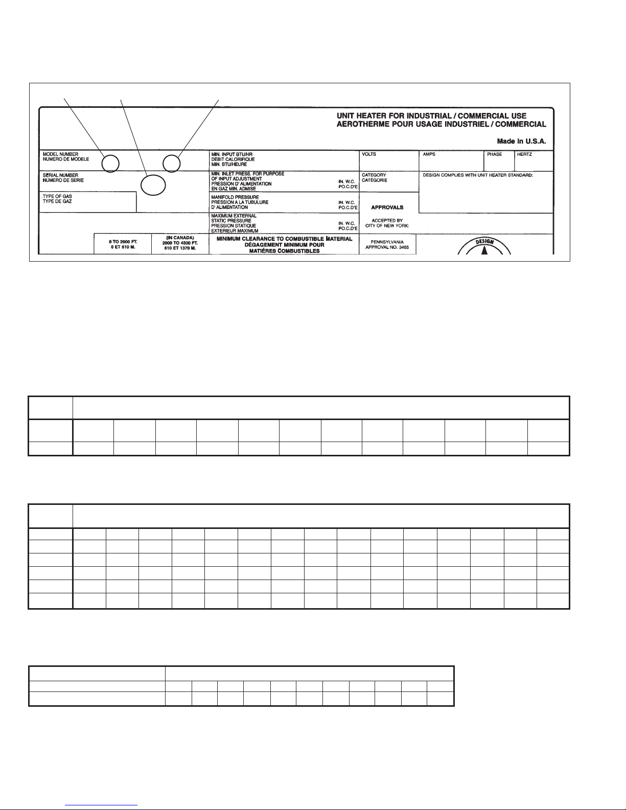
Identifying the Model, Control Code and
Date of Manufacture
Figure 2.1, shown on the next page, is an example of a typical
serial plate. Markings pertinent to verifying correct application
of the conversion kit are identified and explained in detail. All
prerequisites must be satisfied before the unit is deemed
convertible.
1. The first two or three characters in the model number box
are letters. These letters identify the style of the heater. If
any of the following model prefixes appear in this box, the
unit is potentially convertible: PD/BD, PDP/BDP, PV/BV,
DJE, IJE, DFG, IFG, NFG, DFP, IFP, DFS, IFS.
2. Next, the number 11, 12, 13, 14, 30, 31, 32, or 33 must be
the control code or digits 11 and 12 of the model number
are N1 or S1. This is item (2) in Figure 2.1. Any other
number code disqualifies the unit for conversion.
3. Item (3) in Figure 2.1 in the serial number box designates
the date the unit was built. In Figure 2.1, the numbers
3601 are shown. This number is interpreted as the thirty
sixth week of 2001. Prior to January 1995, the digits
preceding the year represent month of manufacture. After
January 1995, the (2) digits proceeding the year represent
the week of manufacture. Any serial number dated 4/91 or
after is acceptable for conversion.
THIS MANUAL IS THE PROPERTY OF THE OWNER. PLEASE BE SURE TO LEAVE IT WITH THE OWNER WHEN YOU LEAVE THE JOB.
NATURAL TO PROPANE CONVERSION KIT SELECTION GUIDE
Figure 2.1
Typical Serial Plate
j lk
Modine Manufacturing Company
1221 Magnolia Ave., Buena Vista, VA 24416; Phone: 540-261-2166
PD 250AA0111 115 5.7 1 60
30011013601-0978 6.0 I ANS Z83.8 - 96
Natural 3.5 CGA-2.6-M96
0.0 MEA 293-96-E
Selection of the Proper Kit
Referring to the model number box on the serial plate in Figure
2.1 (above), the prefix letters and succeeding numbers which are
needed for kit selection are PD250.
The letters identify the model, and the numbers indicate the size
of the unit. Referring to Tables 2.1, 2.2, or 2.3 locate the model
type column (i.e. PD, BD, etc.). Working with Table 2.1 and the
row labeled PD/BD, move right searching for the proper model
size. Read the kit number suffix directly below the model size
for a PD250. Add this suffix (-9) to the base part number for the
propane conversion kit shown in the heading of Table 2.1. The
correct kit for a PD250 with Control Code 11, is 3H034670-9.
Table 2.1
Natural Gas to Propane Gas Conversion Kit Selection Guide
Base Kit Number – 3H034670…(Choose correct suffix -1, -2, -3, etc…)
Model
Type
PD/BD,
PDP/BDP 30 50 75 100 125 150 175 200 250 300 350 400
Suffix -1 -2 -3 -4 -5 -6 -7 -8 -9 -10 -11 -12
Model Size
Table 2.2
Natural Gas to Propane Gas Conversion Kit Selection Guide (For units manufactured after April 1, 1991)
Base Kit Number – 3H33749…(Choose correct suffix -1, -2, -3 etc., per instructions, before ordering propane conversion kits.)
Model
Type
PAE/BAE 30 50 75 100 125 145 – 175 200 225 – 250 300 350 400
Suffix -1 -2 *-14 -4 -5 -6 – -7 -8 -9 – -10 -11 -12 -13
PV/BV 30 50 75 100 125 145 – 175 200 – – 250 300 350 400
Suffix -1 -2 -14 -4 -5 -6 – -7 -8 – – -10 -11 -12 -13
DJE/DHE – – 75 100 125 – 150 – 200 225 – 250 300 350 400
Suffix – – -14 -15 -16 – -6 – -8 -17 – -10 -11 -18 -13
Model Size
* For units manufactured after September, 1993. For units manufactured prior to this date, consult the factory.
Table 2.3
Natural Gas to Propane Gas Conversion Kit Selection Guide
Base Kit Number – 3H036483…(Choose correct suffix -1, -2, -3 etc...)
Model Type Model Size
DFG/IFG/NFG, DFP/IFP, DFS/IFS 75 100 125 150 175 200 225 250 300 350 400
Suffix -1 -2 -3 -4 -5 -6 -7 -8 -9 -10 -11
2
75-511.13

INSTALLATION
Installation of Kit
Conversion of any unit is the responsibility of, and the
risk of the person making the conversion.
1. All field gas piping must be pressure/leak tested prior to
operation. Never use an open flame. Use a soap solution
or equivalent for testing.
2. Gas supply shall be shut-off and the electrical power
disconnected before proceeding with the conversion.
Failure to do so could result in re, explosion or electrical
shock.
General
1. Shut off gas supply to the unit. Disconnect the electrical
power to the unit.
2. For codes 11, 12, 13, 14 or if digit 11 of the model number
is S or T and digit 12 is 1, disconnect the pilot gas tube
and thermocouple lead at the combination gas control. For
codes 30, 31, 32, 33 or if digit 11 of the model number is
N or P and if digit 12 is 1, disconnect the pilot gas tube at
the combination gas control and the ignition cable(s) at the
ignition control.
3. Remove burner assembly.
For PD/BD, PDP/BDP, and PV/BV Models
Lower bottom pan to expose burner and manifold (see Figure
3.1).
For codes 11, 12, 13, or 14, disconnect pilot gas tube and
thermocouple lead at the controls. For codes 30, 31, 32, or 33,
disconnect the pilot gas tube at the combination gas control and
the ignition cable(s) at the ignition control.
Remove the two burner retaining pins holding the burner in place
(see Figure 3.2). The burner can then be easily lowered from
the unit. In replacing the burner, be certain that the slots at the
front of the burner are located properly on their shoulder rivets
and that the burner retaining pins are put back into their proper
locations.
After removing burner assembly, proceed with step #4, page 4.
WARNING
Figure 3.1
Hinged Bottom for Burner Service
Figure 3.2
Manifold Adjustment
MIXER
TUBES
BURNER
RETAINING PIN
For Indoor Duct Furnace Models
On DHE/IHE models, lower the controls enclosure cover and
disconnect the pilot gas supply line and thermocouple at the gas
valve. On models DJE/IJE, DFG/IFG/NFG, DFP/IFP, DBG/IBG,
DCG/ICG, DBP/IBP, and DCP/ICP models, the gas controls are
exposed. On models DFS/IFS, remove lower assess door to
expose gas controls and burner.
The burner may be removed from either side of the duct furnace.
To remove the burner, remove all of the sheet metal screws
holding the side burner access panel in place. (Note: with the
side access panel screws removed, the access panel is free to
move, be careful not to drop the panel.)
Figure 3.3
75-511.13
BURNER SIDE
ACCESS PANEL
BURNER
ALIGNMENT PINS
PILOT
TUBE
THERMOCOUPLE
GAS
VALV E
LEAD
3

INSTALLATION
Remove the side access panel to expose the furnace burner
assembly.
For DJE, IJE, DHE, and IHE carefully thread the pilot tube and
the thermocouple leads through the combustion air slot (at the
rear of the unit) into the burner box so they may be drawn out
with the burner.
Slide the complete burner assembly out of the burner box. The
complete burner and pilot assembly are now free for service
(see Fig. 4.1).
To replace the burner, follow the above steps in reverse order,
being careful to align the burner assembly properly on the
alignment pins on the access panels on both sides of the duct
furnace (see Fig. 3.3).
4. Remove pilot gas tube at the pilot, and exchange pilot
orifice (see Figures 4.2 and 4.3) as follows:
• For Robertshaw pilots, replace the pilot orifice stamped
N18 with the pilot orifice supplied in the conversion kit
stamped LP10.
• For Honeywell pilots, replace the pilot orifice stamped
BCR-18 with the pilot orifice supplied in the conversion
kit stamped BBR - 11 or 12.
• For PSE pilots, replace the pilot orifice stamped 018N
with the pilot orifice supplied in the conversion kit
stamped 012LP.
Figure 4.3 - Pilot Assembly
PILOT
BURNER
PILOT
ORIFICE
THERMOCOUPLE
5. Verify that pilot is oriented to main burner as shown in
Fig. 4.3.
6. Exchange main burner orifice(s) and install air shutters
(see Figure 4.4). Check the orifice number stamped on
each orifice. Be sure that this number is the same number
indicated on the kit parts list for the kit being installed. (See
Table 5.1 or 5.2).
Figure 4.1 - Burner Assembly Figure 4.4 - Burner Orifices and Air Shutters
BURNER
ASSEMBLY
PILOT
ASSEMBLY
THERMOCOUPLE
LEAD
GAS VALVE
PILOT
TUBE
AIR
SHUTTERS
MANIFOLD
MIXER
TUBES
MAIN BURNER
ORIFICES
Figure 4.2 - Pilot Assemblies & Orifices
Robertshaw Pilot Assembly
PILOT BURNER ASSEMBLY
(standing pilot shown)
Honeywell Pilot Assembly PSE Pilot Assembly
PILOT ORIFICE IDENTITY
NUMBER STAMPED HERE
(Natural Gas N18,
Propane Gas 10 LP)
PILOT TUBE WITH
COMPRESSION
SLEEVE AND NUT
4
PILOT ORIFICE IDENTITY
NUMBER STAMPED HERE
(Natural Gas BCR-18,
Propane Gas BBR-11 or 12)
PILOT TUBE WITH
COMPRESSION
SLEEVE AND NUT
75-511.13
PILOT ORIFICE IDENTITY
NUMBER STAMPED HERE
(Natural Gas 018N,
Propane Gas 012 LP)
PILOT TUBE WITH
COMPRESSION
SLEEVE AND NUT

INSTALLATION
Table 5.1 – Conversion Kit Parts List, Natural to Propane for Base Kit 3H034670-xxxx (Refer to Table 2.1)
Qty Part Number -1 -2 -3 -4 -5 -6 -7 -8 -9 -10 -11 -12
Regulator Kit for
Honeywell VR8200, 1 393691 x x x x x x x x x x x
VR8300, VR8204, VR8304
Regulator Kit for Honeywell
V800, VR800, VR8440
Regulator Kit for Robertshaw
7200ER, 7200IPER
Regulator Kit for Robertshaw
7000BER/BDER/ERHC/DERHC
Regulator Kit for
Robertshaw 7222IPER
Regulator Kit for
White-Rogers 36E, 36C
Main Burner Orifice ( ) 5H54751 52 45 39 45 43 39 43 42 36 39 41 42
Drill Size Qty (1) (1) (1) (2) (2) (2) (3) (3) (3) (4) (5) (6)
Table 5.2 – Conversion Kit Parts List, Natural to Propane for Base Kit 3H033749-xxxx (Refer to Table 2.2)
Qty. Part Number -1 -2 -3 -4 -5 -6 -7 -8 -9 -10 -11 -12 -13 -14 -15 -16 -17 -18
Regulator Kit for
Honeywell VR8200 1 393691 X X X X X X X X X
VR8300, VR8204, VR8304
Regulator Kit for Honeywell
V800, VR800, VR8440
Regulator Kit for Robertshaw
7200ER, 7200IPER
Regulator Kit for Robertshaw
7000BER/BDER/ERHC/DERHC
Regulator Kit for
Robertshaw 7222IPER
Main Burner Orifice ( ) 5H54751B… 52 45 49 45 42 45 43 40 43 42 43 39 40 37 45 48 37 43
Drill Size Qty. (1) (1) (2) (2) (2) (3) (3) (3) (4) (4) (5) (5) (6) (1) (2) (3) (3) (6)
Carton Label 1 5H73133C… 1 2 3 4 5 6 7 8 9 10 11 12 13 14 15 16 17 18
Description Qty. Part Number
Honeywell Pilot Orifice 1 Orifice Stamp BBR-11
Parts Common To Kits: Robertshaw Pilot Orifice 1 Orifice Stamp 10 LP
(Table 5.1 and Table 5.2) PSE Pilot Orifice 1 Orifice Stamp 012 LP
Air Shutter Same As Main Burner Orifice Qty. 3H20634A2
Gas Designation Disc 1 5H604841A
Conversion Kit Rating Plate 1 5H73734A
Instruction Sheet 1 5H72298A
1 391937 x x
1 78776 x x x x x x x x
1 85478 x x x x
1 54302 x x x x x
1 92-0659 x x x x x x x x x x x x
1 391937 X X X X X X X X X X X X X X X X
1 78776 X X X X X
1 85478 X X X X X X X X
1 54302 X X X X X X X X X X X X X X
{
Table 5.3 – Conversion Kit Parts List, Natural to Propane for Base Kit 3H036483-xxxx (Refer to Table 2.3)
Qty. Part Number -1 -2 -3 -4 -5 -6 -7 -8 -9 -10 -11
Regulator Kit for
Honeywell VR8204, VR8200A, 1 5H71926A2 X X X X X X X X X X X
VR8300A
Regulator Kit for Honeywell
V800A
Regulator Kit for Robertshaw
7200IPER, 7200ER
Regulator Kit for Robertshaw
700BDER, 700DERHC, 1 5H73134A2 X X X X X
7000BER, 7000ERHC
Regulator Kit for White Rodgers
1 5H73134A2 X X X X X X X X X X X
36E36, 36C38, 36C03
Main Burner Orifice ( ) 5H54751B 37 45 42 45 43 40 37 42 37 43 42
Drill Size Qty (1) (2) (2) (3) (3) (3) (3) (4) (4) (6) (6)
Carton Label 1 5H78020B 1 2 3 4 5 6 7 8 9 10 11
Description Qty. Part Number
Robertshaw Pilot Orifice 1 5H71962A2
Parts Common To Kit: Air Shutter Same As Main Burner Orifice Qty. 3H20634A2
(Table 5.3) Gas Designation Disc 1 5H604841A
Conversion Kit Rating Plate 1 5H73734A
Instruction Sheet 1 5H72298A
1 5H7057A2 X
1 5H73135A2 X X X X X X
{
75-511.13
5

WARNING
MISE EN GARDE
VALVE CONVERTED FOR USE AT
4.2" - 11.0" W.C. IMPROPER OPERATION
COULD RESULT IN DEATH OR
SERIOUS INJURY.
SOUPAPE CONVERTIE POUR USAGE
A COLONNE D'EAU DE 10.6 A 28CM.
UN FONCTIONNEMENT INAPPROPRIE
PEUT PROVOQUER LA MORT OU DES
BLESSURES GRAVES
INSTALLATION
7. Reinstall the burner assembly making certain that the
retaining pins (and clips) are replaced and the burner is
correctly positioned.
8. For codes 11 or 12 or if digit 11 of model number is S and
digit 12 is 1, reconnect the pilot gas tube and thermocouple
at the combination gas control. For codes 30 or 31 or if
digit 11 of model number is N and digit 12 is 1, reconnect
the pilot gas tube at the combination gas control and the
ignition cable(s) at the ignition control.
9. Modify the combination gas control regulator to use
propane gas. Follow the instructions in the regulator kit
to convert the combination gas control. Some conversion
kits will have more than one regulator kit and they are
specific to the manufacturer of the combination gas control
(i.e. Honeywell, Robertshaw, etc.). Check the conversion
kit Parts List, Table 5.1, 5.2, or 5.3, for application of the
correct regulator kit. A second check can be made by
finding the model number on the combination gas control
and matching it with the correct kit. Do not attempt to
substitute one regulator kit for another.
10. Affix the propane conversion label to the combination gas
control. This label is supplied with the regulator conversion
kit (see Figure 6.2).
11. Affix the conversion Rating Plate adjacent to the unit's
original rating plate (see Figure 6.3). Be sure that all blanks
on the label are completely filled in (date of conversion,
kit number, and organization/individual performing the
conversion).
12. Remove the natural gas designation disc(s) and replace
with the propane gas designation disc(s) included with the
conversion kit (see Figure 7.1). Note that some units may
use several discs.
13. Turn on the gas supply to the unit.
14. Check the line pressure of the gas supply upstream of
the combination gas control either with a water column
manometer or with a gauge with water column scale. The
supply pressure should be no less than 12 in. w.c. and no
more than 14 in. w.c.
15. Connect the manometer or (gauge) to the outlet pressure
tap designated on the combination gas control.
16. Restore electric supply to unit.
17. Light unit following instructions on unit rating plate. Turn
up thermostat setting to call for heat. After the main
burners light, measure the outlet (manifold) pressure of
the combination gas control. The outlet pressure should
be 10 in. w.c. The outlet pressure can be adjusted at the
combination gas control's regulator. Turning the adjustment
clockwise will increase the outlet pressure while turning it
counterclockwise will decrease the pressure.
18. Verify normal operating sequence of ignition system
according to the Installation & Service Manual.
19. Check for leaks at all joints and connections in the gas
lines. This is most easily done with a soap/water solution.
Simply brush or spray some of the solution on a joint or
connection and look for bubble formation.
20. Observe the main burner flame. The flame should have a
well-defined conical shape with the base anchored to the
burner port. If the flame appears to be lifting or rising above
the burner port (see Figure 6.1), loosen the thumb screw
on the air shutter and slide the shutter forward toward the
mixer tube (see Figure 4.4).
21. If a majority of the flame is yellow, move the air shutter
back away from the mixer tube. Slight yellow tips on a
propane flame are common and are not objectionable.
Adjust pilot flame. Follow instructions in Installation and
Service Manual.
6
Figure 6.1
Lifting Flame
Figure 6.2
Typical Combination Gas Control Conversion Label
Figure 6.3
Conversion Rating Plate
MODINE MANUFACTURING COMPANY
CONVERSION KIT RATING PLATE
This appliance was converted on
to propane gas with kit no. __________________
by: _______________________________________
__________________________________________
which accepts the responsibility that this
conversion has been properly made. Use
parts supplied by Heating Division of Modine
Manufacturing Company. Conversion to be
performed by a qualified service technician.
Appliance model number and input rating: See
existing rating plate.
Inlet gas pressure: Minimum 12" W.C.
Maximum 14" W.C.
Manifold gas pressure: 10" W.C.
Burner orifice size: # __________ drill
Ce générateur d’air chaud a été converti le
___________ pour fonctionner au gaz propane à
l’aide de l’ensemble n° ______________________
par _______________________________________
__________________________________________
(nom et adresse de l’organisme qui a effectué la
conversion), qui accepte l’entière responsabilité
de la conversion.
5H73734A
75-511.13

EQUIPPED
FOR USE
WITH
PROPANE
GAS
NTRL
5H604841A
INSTALLATION
Figure 7.1
Gas Designation Disc
22. See the original rating plate for the unit heater's rated
input. The input can be verified at any time simply by
checking for the correct main burner orifice size and
manifold pressure. This information is presented on the
conversion kit rating plate.
75-511.13
7

Building HVAC Products • Modine Manufacturing Company • 1500 DeKoven Avenue • Racine, Wisconsin 53403-2552
"I" & "O" Model Series - Phone: 1.866.823.1631 (Toll Free) • All Other Model Series - Phone: 1.800.828.4328 (HEAT)
© Modine Manufacturing Company 2016
75-511.13
 Loading...