

Modine Manufacturing IHR 60, IHR 30, IHR 90, IHR 160, IHR 130 Service Manual
!
!
!
!
9 -512
January 2017
INSTALLATION AND SERVICE MANUAL
High Intensity Gas Fired Infrared Unit Heaters
Model IHR, Control Codes 47, 48, 97, 98, 27, and 67
INSTRUCTIONS APPLY TO:
Installation Operation Maintenance
WARNING
Improper installation, adjustment, alteration,
service or maintenance can cause property
damage, injury or death. Read the installation,
operating, and service/maintenance instructions
thoroughly before installing or servicing this
equipment.
WARNING
Gas-Fired appliances are not designed for use in
hazardous atmospheres containing flammable
vapors or combustible dust, or atmospheres
containing chlorinated or halogenated
hydrocarbons.
FOR YOUR SAFETY
The use and storage of gasoline or other flammable
vapors and liquids in the vicinity of this appliance is
hazardous.
FOR YOUR SAFETY
If you smell gas:
1. Open Windows.
2. Do not touch electrical Switches.
3. Extinguish any open flame.
4. Immediately call your gas supplier.
5. If gas supplier cannot be reached, call fire
department.
FOR INDOOR INSTALLATION ONLY.
NOT FOR RESIDENTIAL USE.
HAZARD INTENSITY LEVELS
• DANGER: Failure to comply will result in severe
personal injury or death and property damage
• WARNING : Failure to comply could result in severe
personal injury or death and/or property damage.
• CAUTION: Failure to comply could result in minor
personal injury and/or property damage.
CONTENTS
Section Page
1. Safety ....................................................................3
2. Installation ............................................................. 9
3. Operation ............................................................19
4. Maintenance .......................................................20
5. Limited Warranty ................................................. 24
These heaters must NOT be used in the
following applications:
• Enclosed swimming pool areas
• Areas with contaminated atmospheres.
• Areas requiring explosion-proof equipment.
• Process heating applications.
ATTENTION
Mount a copy of these instructions adjacent
to the heater and retain a copy for future
reference.

IHR Series Manual
Contents
1.0 Safety.................................................................... 3
Safety Symbols ....................................................... 3
Applications .......................................................... 3
Clearance to Combustibles .............................................. 4
Gas Connection....................................................... 6
Standards, Certifications and Government Regulations ........................ 6
Safety Signs and Labels ................................................ 8
2.0 Installation . . . . . . . . . . . . . . . . . . . . . . . . . . . . . . . . . . . . . . . . . . . . . . . . . . . . . . . . . . . . . . . 9
Design . . . . . . . . . . . . . . . . . . . . . . . . . . . . . . . . . . . . . . . . . . . . . . . . . . . . . . . . . . . . . 9
Heater Placement . . . . . . . . . . . . . . . . . . . . . . . . . . . . . . . . . . . . . . . . . . . . . . . . . . . . . 10
Total Area Heating ..................................................10
Spot Heating . . . . . . . . . . . . . . . . . . . . . . . . . . . . . . . . . . . . . . . . . . . . . . . . . . . . . . 11
Heater Mounting . . . . . . . . . . . . . . . . . . . . . . . . . . . . . . . . . . . . . . . . . . . . . . . . . . . . . . 12
Ventilation ...........................................................13
Gas Supply . . . . . . . . . . . . . . . . . . . . . . . . . . . . . . . . . . . . . . . . . . . . . . . . . . . . . . . . . . 14
Leak Testing . . . . . . . . . . . . . . . . . . . . . . . . . . . . . . . . . . . . . . . . . . . . . . . . . . . . . . . . . 16
Electrical Requirements and Wiring Diagrams . . . . . . . . . . . . . . . . . . . . . . . . . . . . . . . 17
3.0 Operation ................................................................19
4.0 M aintenance ..............................................................20
Troubleshooting Guide . . . . . . . . . . . . . . . . . . . . . . . . . . . . . . . . . . . . . . . . . . . . . . . . . 21
Heater Assembly Components ...........................................22
Parts Listing..........................................................23
5.0 Limited Warranty . . . . . . . . . . . . . . . . . . . . . . . . . . . . . . . . . . . . . . . . . . . . . . . . . . . . . . . . . . 24
2
!
!
!
!
!
!
!
IHR Series Manual
1.0 Safety • Safety Symbols • Applications
1.0 Safety
WARNING
Improper installation, adjustment, alteration, service, or maintenance can cause property
damage, serious injury, or death. Read and understand the installation, operating, and
maintenance instructions thoroughly before installing or servicing this equipment. Only
trained, qualified gas installation and service personnel may install or service this
equipment.
Safety Symbols
Safety is the most important consideration during installation, operation, and maintenance of the infrared
heater. You will see the following symbols and signal words when there is a hazard related to safety or
property damage.
Warning indicates a potentially hazardous situation
WARNING
which, if not avoided, could result in death or injury.
Caution indicates a potentially hazardous situation
CAUTION
NOTICE
which, if not avoided, could result in minor or
moderate injury.
Notice indicates a potentially hazardous situation
which, if not avoided, could result in property
damage.
Applications
This is not an explosion proof heater. Consult your local fire marshal, insurance carrier, and other authorities
for approval of the proposed installation.
Commercial / Industrial (Indoor Use Only)
Infrared heaters are designed and certified for use in industrial and commercial buildings such as warehouses,
manufacturing plants, aircraft hangars, and vehicle maintenance shops. For maximum safety, the building
must be evaluated for potential hazards before installing the heater system. A critical safety factor to consider
before installation is the clearance to combustibles.
Residential
This heater is NOT approved for use in any residential application. This includes, but not limited to, attached
garages, living quarters, solariums, etc. Consult the local fire marshal and/or insurance provider if unsure
of your application.
Not For Residential Use.
Installation of an infrared heater system in residential indoor spaces, RV’s,
mobile homes, etc. may result in property damage, asphyxiation, fire, serious
injury, or death.
WARNING
!
1.0 Safety • Clearance to Combustibles
!
IHR Series Manual
Clearance to Combustibles
WARNING
Placement of explosive objects, flammable objects, liquids,
and vapors close to the heater may result in explosion, fire,
property damage, serious injury, or death. Do not store, or use,
explosive objects, liquids, and vapor in the vicinity of the
heater.
Failure to comply with the published clearances to combustibles could result in personal injury, death,
and/or property damage.
CAUTION
Signs shall be posted specifying the maximum permissible stacking height in order to
maintain clearances to combustibles.
Hazards Include:
For maximum safety the building must be evaluated for hazards before installing the heater system.
Examples include, but are not limited to:
• Gas and electrical lines
• Combustible and explosive materials
• Chemical storage areas
• Areas of high chemical fume concentrations
• Provisions for accessibility to the heater
• Adequate clearances around air openings
• Combustion and ventilating air supply
A critical safety factor to consider before installation is the clearances to combustibles. Clearance to
combustibles is defined as the minimum distance you must have between the infrared surface, or reflector,
and the combustible item. Considerations must also be made for moving objects around the infrared heater.
The following is a partial list of items to maintain clearances from:
• Vehicle parking areas
• Vehicles with lifts or cranes
• Storage areas with stacked materials
• Lights
• Sprinkler heads
• Overhead doors and tracks
• Dirty, contaminated environment
Combustible Items Include: Moving Objects Include:
• Wood • Overhead doors
• Paper • Vehicles on lifts
• Fabric • Cranes
• Chemicals • Hoists
• Wall or roof insulation • Car wash equipment
The stated clearance to combustibles represents a surface temperature of 90°F (50°C) above room
temperature. Building materials with a low heat tolerance (such as plastic, vinyl siding, canvas, tri-ply, etc.)
may be subject to degradation at lower temperatures. It is the installer’s responsibility to assure that adjacent
materials are protected from degradation.
When installing the infrared heater system, the minimum clearances to combustibles must be maintained.
These distances are shown in Chart 1.1 and on the heater. If you are unsure of the potential hazards, consult
your local fire marshal, fire insurance carrier, or other qualified authorities on the installation of gas fired
infrared heaters for approval of the proposed installation.
4
IHR Series Manual
1.0 Safety • Clearance to Combustibles
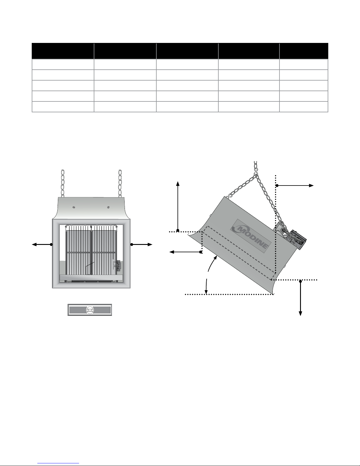
Chart 1.1 • Clearance to Combustibles in Inches (see Figure 1.1)
Model No. Sides Back Top Below/ Front
IHR 30 30 18 28 72
IHR 60 32 18 40 72*
IHR 90 48 30 42 98
IHR 130 48 30 52 120
IHR 160 50 32 60 132
* This clearance is 80 in. when the heater is fitted with a parabolic reflector.
NOTE: If the heater is mounted beneath a non-combustible surface, a 24 in. minimum top clearance must
be maintained from the top of the heater to prevent overheating the controls.
Figure 1.1 • Clearance to Combustibles
Top
SideSide
Front
20° - 35°
Mount Heater Level
- Side to Side -
FRONT VIEW SIDE VIEW
Back
Manifold or
Control End
Below

1.0 Safety • Gas Connection • Standards, Certifications and Government Regulations
!
IHR Series Manual
Gas Connection
WARNING
An approved connector, suitable for the environment of equipment usage, is required.
Visible or excessive swaying, flexing, and vibration of the gas connections must be avoided
to prevent failure. Neither the gas pipe nor the connector shall be placed in the ‘flue
discharge area’. In no case shall the gas supply support the weight of the heater.
To ensure your safety, and comply with the terms of the warranty, all units must be installed in accordance
with these instructions.
Standards, Certifications and Government Regulations
Installation of this infrared heater must comply with all applicable local, state, and national specifications,
regulations and building codes. Contact the local building inspector and/or fire marshal for guidance.
In the absence of local codes, the installation must conform to the latest edition of:
United States: National Fuel Gas Code, ANSI Z223.1 (NFPA 54).
Canada: CAN/CGA B149.1 and .2, Canadian Electrical Code C22.1
Copies of these standards can be viewed or purchased at www.nfpa.org or www.scc.ca.
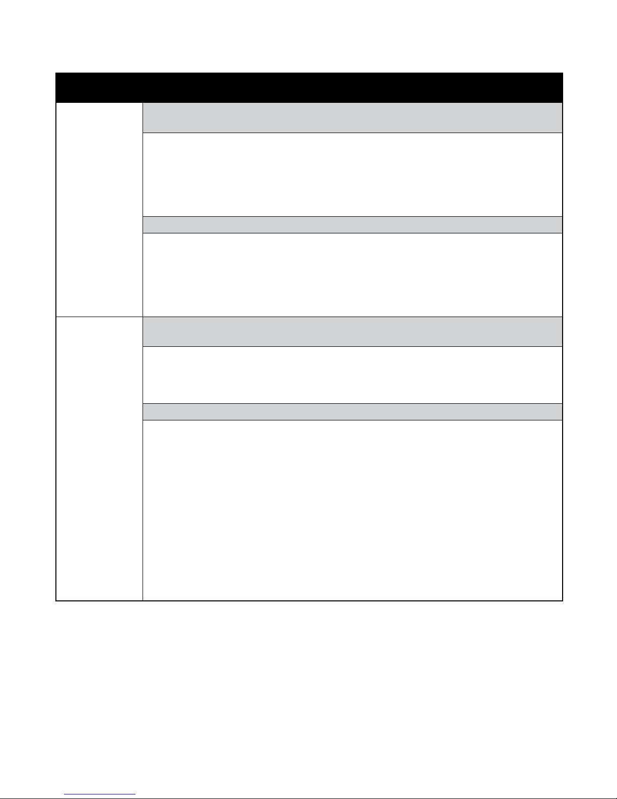
Chart 1.2 • Standards and Code Installation Guidelines • Building Aspect
Building
Aspect
Electrical
Venting
The heater must be electrically grounded in accordance with the following codes:
United States: Refer to National Electrical Code
Wiring must conform to the latest edition of National Electrical Code
ordinances, and any special diagrams furnished.
Canada: Refer to Canadian Electrical Code CSA C22.1 Part 1 (latest edition).
Venting must comply with the requirements within this manual and the following
codes:
United States: Refer to NFPA54/ANSI Z223.1 (latest edition), the National Fuel
Gas Code.
Canada: Refer to CAN/CGA B149.1 Installation Codes for Gas Burning Appliances.
Codes and Guidelines
®
, ANSI/NFPA 70 (latest edition).
®
, local
6
IHR Series Manual
1.0 Safety • Standards, Certifications and Government Regulations
Chart 1.3 • Standards and Code Installation Guidelines • Building Type
Building
Aspect
Public
Garages
Aircraft
Hangars
Codes and Guidelines
Installation of this infrared heater in public garages must conform to the following
codes:
United States:
Standard for Parking Structures NFPA 88A (latest edition) or the
Code for Motor Fuel Dispensing Facilities and Repair Garages NFPA 30A (latest
edition).
Canada: Refer to CAN/CGA B149.1 and B149.2: Installation Codes for Gas
Burning Appliances.
Guidelines:
• Heaters must not be installed less than 8 ft. (2.4 m) above the floor. Minimum
clearances to combustibles must be maintained from vehicles parked below the
heater.
• When installed over hoists, minimum clearances to combustibles must be
maintained from the upper most point of objects on the hoist.
Installation of this infrared heater in aircraft hangars must be in accordance with the
following codes:
United States: Refer to Standard for Aircraft Hangars, ANSI/NFPA 409 (latest
edition).
In Canada: Refer to Standard CAN/CGA B149.1 and B149.2.
Guidelines:
• In aircraft storage and servicing areas, heaters shall be installed at least 10 ft.
(3 m) from above the upper surface of wings or of the engine enclosures of the
highest aircraft that may be housed in the hangar. The measurement shall be
made from the wing or engine enclosure, whichever is higher from the floor, to
the bottom of the heater.
• In areas adjoining the aircraft storage area (e.g., shops, offices) the bottom of
heaters shall be installed no less than 8 ft. (2.4 m) above the floor.
• Suspended or elevated heaters shall be located in spaces where they shall not
be subject to damage by aircraft, cranes, movable scaffolding, or other objects.
Provisions shall be made to assure accessibility to suspended infrared heaters for
recurrent maintenance purposes.
Applicable authorities governing the manufacturing or installation of this heater include (but are
not limited to) the following organizations:
In the United States:
• NFPA 54/ANSI Z223.1 - National Fuel Gas Code.
• ANSI Z83.19/C2.35 - Gas-fired High Intensity
Infrared Heaters.
• ANSI/NFPA 70 - National Electric Code.
• IRSC.
In Canada:
• CAN/CGA B149.1-10 - Natural Gas and
Propane Installation Code.
• ANSI Z83.19/C2.35 - Gas-fired High Intensity
Infrared Heaters.
• C22.1 Part 1 - Canadian Electrical Code.
SAMPLE
1.0 Safety • Safety Signs and Labels
SAMPLE
IHR Series Manual
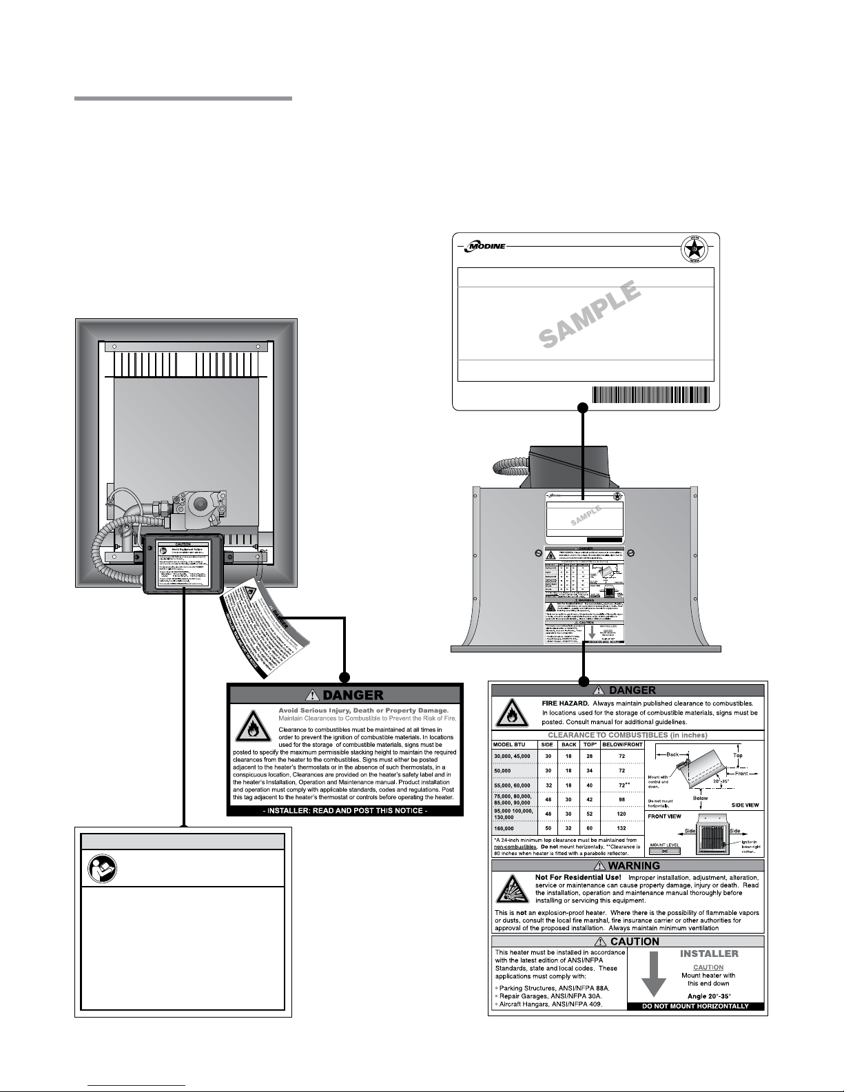
Safety Signs and Labels
It is important to provide warnings to alert individuals to potential hazards and safety actions. ANSI Z83.19
and the National Fuel Gas Code require you to post a sign “specifying the maximum permissible stacking
height to maintain the required clearances from the heater to the combustibles” near the heater’s thermostat
or in absence of such thermostats in a conspicuous location. Signs should state the hazards for the
particular application and be legible to the building occupants. Consult the factory or a factory representative
for additional information on signage compliance.
Safety warning labels must be maintained on the
infrared heater. Illustrations of the safety labels,
and their locations, are pictured below.
Back View
Bottom View
UNVENTED GAS RADIANT HEATER
FOR INDOOR (Non-Residential) INSTALLATION ONLY.
High - Intensity Infrared Heater
MODEL NO.
IHR 60S 47
VOLTS AC:
120V - 60Hz
AMPS - STARTING:
0.1
AMPS - RUNNING:
0.1
DESIGN COMPLIES WITH:
ANSI Z83.19 (latest edition) - Gas Fired High Intensity Infra-Red Heater
MODINE MANUFACTURING COMPANY
1500 DEKOVEN AVENUE - RACINE, WI 53403
1.800.828.4328 (HEAT)
Class IIIA Permanent Label
INPUT BTU/H
60,000
HEATER TYPE:
C1
MANIFOLD PRESSURE:
10.0 INCHES W.C.
MAX. INLET PRESSURE
14.0 INCHES W.C.
www.modinehvac.com
MODEL NO.
IHR 60S 47
VOLTS AC:
120V - 60Hz
AMPS - STARTING:
0.1
AMPS - RUNNING:
0.1
DESIGN COMPLIES WITH:
ANSI Z83.19 (latest edition) - Gas Fired High Intensity Infra-Red Heater
MODINE MANUFACTURING COMPANY
1500 DEKOVEN AVENUE - RACINE, WI 53403
262-636-1200 www.modine.com
UNVENTED GAS RADIANT HEATER
FOR INDOOR (Non-Residential) INSTALLATION ONLY.
High - Intensity Infrared Heater
Class IIIA Permanent Label
INPUT BTU/H
60,000
HEATER TYPE:
C1
MANIFOLD PRESSURE:
10.0 INCHES W.C.
MAX. INLET PRESSURE
14.0 INCHES W.C.
VERSION
05/97
VERSION
05/97
FOR USE WITH
Natural Gas
MIN. INLET PRESSURE FOR
PURPOSE OF ADJUSTMENT
11.0 INCHES W.C.
MIN. MOUNTING ANGLE
20 DEGREES
MAX. MOUNTING ANGLE
35 DEGREES
Serial No. 0807MODI123456001
FOR USE WITH
Natural Gas
MIN. INLET PRESSURE FOR
PURPOSE OF ADJUSTMENT
11.0 INCHES W.C.
MIN. MOUNTING ANGLE
20 DEGREES
MAX. MOUNTING ANGLE
35 DEGREES
Serial No. 0807MODI123456001
Rating Plate
CAUTION
Avoid Equipment Failure
Consult manual for installation guidelines.
Connect proper VOLTA GE as noted on gas valve and heater’s
rating label (25VAC or 120VAC).
Proper POLARITY must be observed. Hot line of electrical
source must be connected to black wire; neutral line to white wire.
For proper operation, green line must connect to POSITIVE
EARTH on all 120VAC heaters.
Observe listed inlet GAS PRESSURES.
Natural Gas: 7 Inches W.C. Min. 14 Inches W.C. Max.
L.P. Gas: 11 Inches W.C. Min. 14 Inches W.C. Max.
Observe 20°-35° MOUNTING ANGLE. DO NOT mount
horizontally. Consult installation manual.
Reference the WIRING DIAGRAM located inside this box.
F/N: LLDR002
F/N: LL01 - Clearance
Safety Tag
(Affix adjacent to
heater’s thermostat)
8
F/N: LLDCL002
Clearance to Combustibles Label
 Loading...