

Modine Manufacturing 1-500, HOT DAWG H2O HHD Service Manual
1-500
5H081501
HOT DAWG H2O® - Low Profile Hot Water Unit Heater
WARNING
Improper installation, adjustment, alteration,
service or maintenance can cause property
damage, injury or death. Read the installation,
operating and maintenance instructions
thoroughly before installing or servicing this
equipment.
IMPORTANT
The use of this manual is specifically intended
for a qualified installation and service agency. A
qualified installation and service agency must
perform all installation and service of these
appliances.
General Information
Installation and service instructions in this manual are
applicable to model HHD, low profile hot water unit heaters,
which should be installed in their proper applications for their
most effective function as heating units.
The water coils are warranted for operation at water pressures
up to 150 psi and temperatures up to 200°F.
Motors are designed for continuous duty. They can operate in
a maximum ambient temperature of 104°F (40°C).
The unit heaters are listed by ETL as certified. Units not
approved for use in potable water systems.
THIS MANUAL IS THE PROPERTY OF THE OWNER.
PLEASE BE SURE TO LEAVE IT WITH THE OWNER WHEN YOU LEAVE THE JOB.
October, 2010
INSTALLATION AND SERVICE MANUAL
Model HHD
Table of Contents
General Information……………………………………..
Inspection on Arrival…………………………………….
Special Precautions……………………………………..
SI (Metric) Conversion Factors………………………...
Installation
Unit Location…………………………………………
Unit Mounting………………………………………..
Hot Water Piping…………………………………….
Electrical Connections………………………………
Start-Up Procedure
Prior to Operation……………………………………
Initial Start-Up………………………………………..
Typical Sequence of Operation……………………
Troubleshooting……………………………………..
Unit Data
Dimensions…………………………………………..
Electrical Data……………………………………….
Mechanical Data…………………………………….
Performance Data…………………………………...
Maintenance/Replacement Parts……………………...
Warranty………………………………………………….
Inspection upon Arrival
1. Inspect unit upon arrival. In case of damage, report
immediately to transportation company and your local
factory sales representative.
2. Check rating plate on unit to verify that the power supply
meets available electric power at the point of installation.
3. Inspect unit received for conformance with description of
product ordered (including specifications where
applicable).
Note: Modine Manufacturing Company has a continuous
product improvement program, and therefore reserves the right
to change design and specifications without notice.
1
1
2
2
3
4-5
6
6
7
7
7
7
8
8
8
9
10
12
SPECIAL PRECAUTIONS
THE INSTALLATION AND MAINTENANCE INSTRUCTIONS IN
THIS MANUAL MUST BE FOLLOWED TO PROVIDE SAFE,
EFFICIENT, AND TROUBLE-FREE OPERATION. IN ADDITION,
PARTICULAR CARE MUST BE EXERCISED REGARDING THE
SPECIAL PRECAUTIONS LISTED BELOW. FAILURE TO
PROPERLY ADDRESS THESE CRITICAL AREAS COULD
RESULT IN PROPERY DAMAGE OR LOSS, PERSONAL INJURY,
OR DEATH. THESE INSTRUCTIONS ARE SUBJECT TO ANY
MORE RESTRICTIVE LOCAL OR NATIONAL CODES.
HAZARD INTENSITY LEVELS
1. DANGER: Indicates an imminently hazardous situation which,
if not avoided, WILL result in death or serious injury.
WARNING: Indicates a potentially hazardous situation which,
2.
if not avoided, COULD result in death or serious injury.
CAUTION: Indicates a potentially hazardous situation which, if
3.
not avoided, MAY result in minor or moderate injury.
IMPORTANT: Indicates a situation which, if not avoided, MAY
4.
result in a potential safety concern.
DANGER
Units must not be installed where they may be exposed to
potentially explosive or flammable atmosphere.
WARNING
1. Disconnect power supply before making wiring
connections to prevent electrical shock and equipment
damage.
2. All appliances must be wired strictly in accordance with
the wiring diagram furnished with the appliance. Any
wiring different from the wiring diagram could result in a
hazard to persons and property.
3. Any original factory wiring that requires replacement
must be replaced with wiring material having a
temperature rating of at least 105°C.
4. Ensure that the supply voltage to the appliance, as
indicated on the serial plate, is not 5% greater than the
rated voltage.
5. When servicing or repairing of this equipment, use only
factory-approved service replacement parts. A
complete replacement parts list may be obtained by
contacting Modine Manufacturing Company. Refer to
the rating plate on the unit for complete model and serial
number and Company address. Any substitution of
parts or controls not approved by the factory will be at
the owner’s risk.
CAUTION
1. All literature shipped with this unit should be kept for
future use for servicing or service diagnostics. Leave
manual with the owner. Do not discard any literature
shipped with this unit.
2. Consult piping and electrical instructions in this manual
before final installation.
CAUTION
3. Units are designed for use in heating applications with
ambient temperatures between 40°F and 100°F.
Heaters should not be used in applications where the
heated space temperature is below 40°F unless a glycol
anti-freeze solution has been added.
4. Units not approved for use in potable water systems.
5. Do not install units below 7' measured from the bottom
of the unit to the floor in commercial applications (unless
unit is properly guarded to provide user protection from
moving parts) and 5' measured from the bottom of the
unit to the floor in residential applications.
6. Do not reuse any mechanical or electrical components
which have been wet. Replace defective components.
7. Do not operate the unit with steam. The coil is not
designed for steam condensate removal which can
damage the unit.
8. Ensure the supply voltage to the appliance, as indicated
on the serial plate, is not 5% less than the rated voltage.
IMPORTANT
1. Start-up and adjustment procedures should be
performed by a qualified service agency.
2. Be sure no obstructions block air intake and discharge
of unit heaters. Do not attach ductwork or air filters to
this unit heater. Maintain a minimum of 6” clearance to
inlet openings.
3. When mounting the unit to the joists, do not compress
the vibration isolators by over tightening the lag bolt
screws into the joist. Doing so will greatly reduce the
ability of the isolator to dampen vibration.
4. No water-flow can cause a freeze condition resulting in
damage to the coil.
5. Never leave the unit filled with water in a building
without heat unless antifreeze has been added.
6. To check most of the Possible Remedies in the
troubleshooting guide listed in Table 7.1, refer to the
applicable sections of the manual.
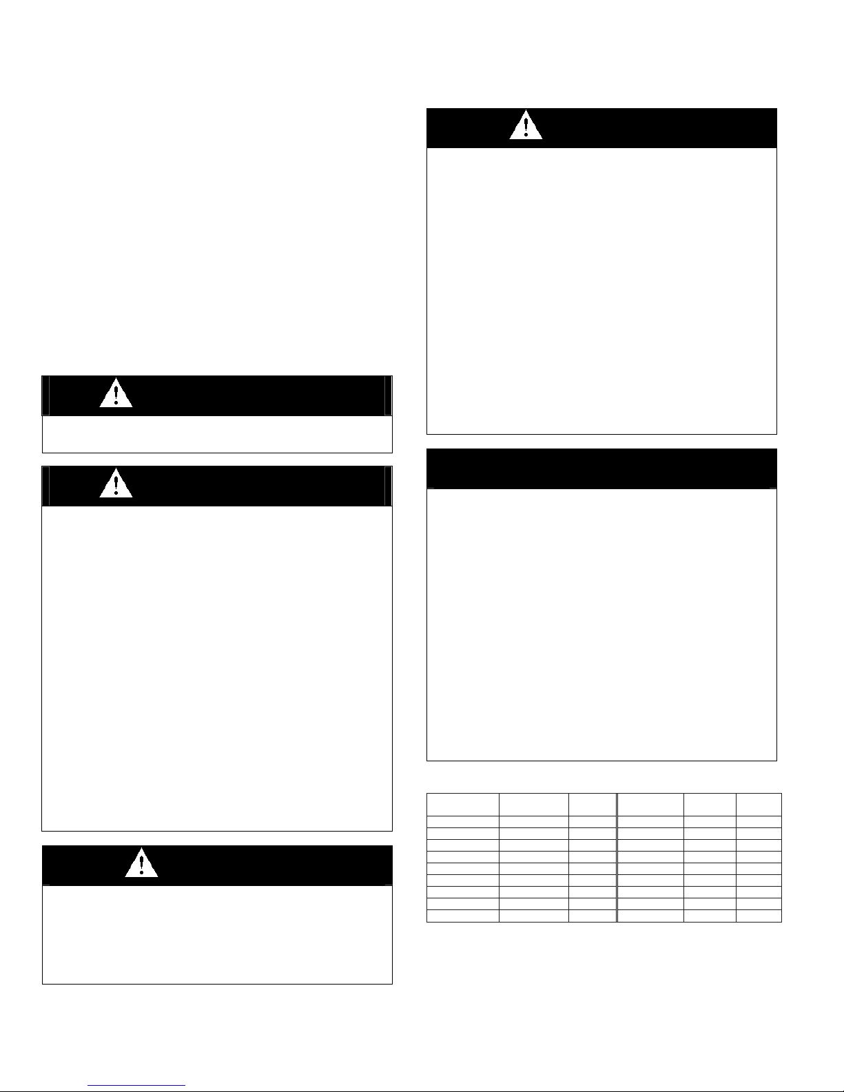
Table 2.1 – SI (Metric) Conversion Factors
To Convert Multiply By To
Obtain
“W.C. 0.249 kPa feet 0.305 m
ºF (ºF-32) x 5/9 ºC Gal/hr 0.00379 m³/hr
BTU 1.06 kJ Gal/hr 3.79 l/hr
BTU/ft3 37.3 kJ/m³ gallons 3.79 l
BTU/hr 0.000293 kW Horsepower 746 W
CFH (ft3/hr) 0.000472 m³/min inches 25.4 mm
CFH (ft3/hr) 0.00000787 m³/s pound 0.454 kg
CFM (ft3/min) 0.0283 m³/min psig 6.89 kPa
CFM (ft3/min) 0.000472 m³/s psig 27.7 “W.C.
To Convert Multiply
By
To
Obtain
2 1-500
INSTALLATION – UNIT LOCATION
DANGER
Units must not be installed where they may be exposed to
potentially explosive or flammable atmosphere.
CAUTION
1. All literature shipped with this unit should be kept for
future use for servicing or service diagnostics. Leave
manual with the owner. Do not discard any literature
shipped with this unit.
2. Consult piping and electrical instructions in this manual
before final installation.
3. Units are designed for use in heating applications with
ambient temperatures between 40°F and 100°F.
Heaters should not be used in applications where the
heated space temperature is below 40°F unless a glycol
anti-freeze solution has been added.
4. Units not approved for use in potable water systems.
IMPORTANT
the unit can be flipped 180° from the way it was received
from the factory. By doing so, the sides become opposite
but the front and back remain in the same relative position.
The bottom panel now becomes the top panel and viceversa. Be sure to remove the spring loaded deflector
blades, turn them over, replace, and adjust so they are open
and in a position to direct the heated air down to the floor.
Note that the labels on the front of the unit will be upside
down. New stickers can be purchased from Modine.
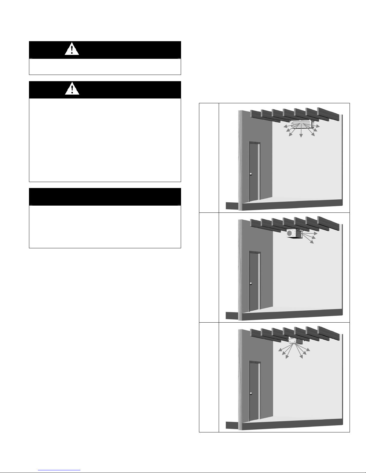
Figure 3.1 – Model HHD Mounting Orientations
Horizontal Air Delivery,
Perpendicular to Joists
1. Start-up and adjustment procedures should be
performed by a qualified service agency.
2. Be sure no obstructions block air intake and discharge
of unit heaters. Do not attach ductwork or air filters to
this unit heater. Maintain a minimum of 6” clearance to
inlet openings.
1. Units should not be installed in atmospheres where
corrosive fumes or sprays are present.
2. When locating the heater, consider general space and
heating requirements and availability of hot water and
electrical supply.
3. Be sure the structural support at the unit location site is
adequate to support the unit’s weight.
4. Determine mounting orientation of the unit heater.
Figure 3.1 shows three typical orientations. Additional
details can be seen in Figure 5.2.
5. Be sure no obstructions block air intake and discharge
of unit heaters. Do not attach ductwork or air filters to
this unit heater. Maintain a minimum of 6” clearance to
inlet openings. Failure to do so will result in poor unit
performance.
6. Unit heaters installed in a building exposed to a
prevailing wind should be located to direct a major
volume of heated air along the windward wall.
7. Vertical delivery unit heaters should generally be
located in the central area of the space to be heated.
Place horizontal delivery units along the walls of the
same building where heat loss is usually greatest.
8. Locate units so they do not blow directly at occupants.
9. Locate units so their air streams blanket exposed walls.
Reversing Electrical/Piping Connection Access
Units feature electrical access on the left and piping
connections on the right as standard (when looking at the
unit). If the installation requires the access to be reversed,
Parallel to Joists
Horizontal Air Delivery,
Vertical Air Delivery,
Recessed Between Joists
1-500 3
INSTALLATION – UNIT MOUNTING
CAUTION
Do not install units below 7' measured from the bottom of the
unit to the floor in commercial applications (unless unit is
properly guarded to provide user protection from moving
parts) and 5' measured from the bottom of the unit to the
floor in residential applications.
IMPORTANT
When mounting the unit to the joists, do not compress the
vibration isolators by over tightening the lag bolt screws into
the joist. Doing so will greatly reduce the ability of the
isolator to dampen vibration.
1. Be sure the means of suspension is adequate to
support the weight of the unit (see Table 8.1 for unit
weights).
2. Before lifting the heater for suspension, based on the
mounting orientation selected (refer to Figure 3.1), the
mounting brackets must be installed on the unit as
follows:
For Horizontal Air Delivery Orientations:
a) Position the brackets on the top of the unit as
shown in Figure 4.1.
For Vertical Air Delivery Orientations:
a) Position the brackets on the side of the unit as
shown in Figure 5.1. Note the following:
• For 10” or 12” deep joists, the bracket can be
oriented as shown in the top picture.
• For 12” deep joists, the bracket can be oriented
as shown in the bottom picture for additional
headroom. Refer also to Figure 5.2.
• If required, louver blades can be flipped to
change the direction of airflow control. To do
so, remove the spring loaded deflector blades,
turn them over, replace, and adjust so they are
open and in a position to direct the heated air.
For All Units:
b) Secure the brackets to the unit with the 3/8”-16 x 1”
Hex Bolts and 3/8” Lock Washers included with the
bracket kit. The bolts thread into the retaining nuts
that are located in the top of the unit casing.
c) Repeat for the bracket on the left side of the unit
(not pictured).
d) Install the vibration isolators that were supplied with
the unit (see Figure 4.1) by inserting the smaller
diameter pieces through the ¾” diameter holes from
the top side of the bracket. The larger diameter
pieces are fitted from the bottom side. The outer
diameter of the top mounted pieces will friction fit
into the inside diameter of the bottom pieces.
3. With the brackets installed on the unit, the unit can be
installed to the ceiling joists or trusses as follows (refer
to Figure 5.2):
• The bracket mounting hole locations accommodate
joists on 16" centerlines.
• Use (4) 1/4" lag bolt screws (supplied by others) that
are at least 3” long. The (4) 1-1/2” x 1/4” Fender
Washers (supplied by Modine) must be placed
between the lag bolt screw and bottom vibration
isolation piece
• Install the lag bolt screws until the top of the isolator
just touches the bottom of the joist. Do not
compress the isolator by over tightening the lag bolt
screw. Doing so will greatly reduce the ability of the
isolator to dampen vibration.
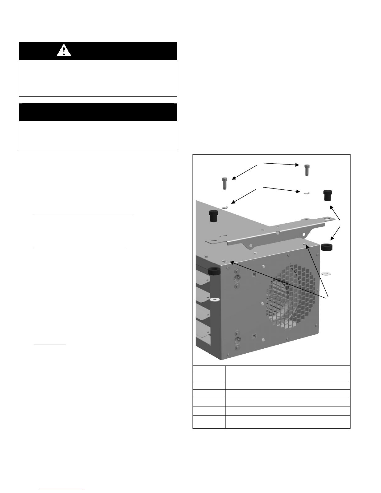
Figure 4.1
Bracket Installation for Horizontal Air Delivery
c
d
e
h
f
Item Qty (total for unit) - Description
c
d
e
f
g
h
Note: Figure 4.1 shows the unit with standard right hand piping
connections. See page 3 for instructions on reversing the piping
access side.
Qty (4) – Hex Bolts, 3/8"-16 x1"
Qty (4) – 3/8” Lock Washers
Qty (2) – Mounting Brackets
Qty (4) – Retainer Nuts , 3/8"-16
Qty (4) – Two-Piece Vibration Isolators
Qty (4) – 1-1/2” x 1/4” Fender Washers
(used when the unit is installed to the joists)
g
4 1-500
 Loading...