

Modine Manufacturing HER Installation And Service Manual
INSTALLATION AND SERVICE MANUAL
WARNING
Improper installation, adjustment, alteration,
service or maintenance can cause property
damage, injury or death, and could cause
exposure to substances which have been
determined by various state agencies to cause
cancer, birth defects or other reproductive
harm. Read the installation, operating and
maintenance instructions thoroughly before
installing or servicing this equipment.
IMPORTANT
The use of this manual is specifically intended
for a qualified installation and service agency.
A qualified installation and service agency must
perform all installation and service of these
appliances.
2-525.3
5H75690
January, 2013
electric unit heaters
model HER
FOR YOUR SAFETY
The use and storage of gasoline or other
flammable vapors and liquids in open containers
in the vicinity of this appliance is hazardous.
Inspection on Arrival
1. Inspect unit upon arrival. In case of damage, report it
immediately to transportation company and your local
Modine sales representative.
2. Check rating plate on unit to verify that power supply and
motor specification requirements meets available electric
power at the point of installation.
3. Inspect unit upon arrival for conformance with description of
product ordered (including specifications where applicable).
General Information
Installation and wiring of these electric unit heaters must
conform to all applicable local codes and the National Electric
Code. Wiring of these electric unit heaters should only be
performed by a qualified electrician.
Table of Contents
General Information ................................................................... 1
Special Precautions / Important Information.............................. 2
SI (Metric) Conversion Factors ................................................. 2
Unit Location ............................................................................. 3
Unit Mounting ............................................................................ 3
Installation ................................................................................. 4
Electrical Connections .......................................................... 4
Operation ................................................................................... 5
Operating Sequence ............................................................. 5
Dimensional Data ..................................................................... .6
Performance Data ..................................................................... 6
Motor Specifications .................................................................. 6
General Maintenance & Troubleshooting. ................................. 7
Warranty .....................................................................Back Page
PLEASE BE SURE TO LEAVE IT WITH THE OWNER WHEN YOU LEAVE THE JOB.
THIS MANUAL IS THE PROPERTY OF THE OWNER.
SPECIAL PRECAUTIONS / IMPORTANT INSTRUCTIONS
SPECIAL PRECAUTIONS / IMPORTANT
INSTRUCTIONS
THE INSTALLATION AND MAINTENANCE INSTRUCTIONS
IN THIS MANUAL MUST BE FOLLOWED TO PROVIDE SAFE,
EFFICIENT AND TROUBLE-FREE OPERATION. IN ADDITION,
PARTICULAR CARE MUST BE EXERCISED REGARDING
THE SPECIAL PRECAUTIONS LISTED BELOW. FAILURE
TO PROPERLY ADDRESS THESE CRITICAL AREAS COULD
RESULT IN PROPERTY DAMAGE OR LOSS, PERSONAL
INJURY, OR DEATH. THESE INSTRUCTIONS ARE SUBJECT
TO ANY MORE RESTRICTIVE LOCAL OR NATIONAL CODES.
HAZARD INTENSITY LEVELS
1. DANGER: Indicates an imminently hazardous situation
which, if not avoided, WILL result in death or serious injury.
2. WARNING: Indicates a potentially hazardous situation which,
if not avoided, COULD result in death or serious injury.
3. CAUTION: Indicates a potentially hazardous situation which,
if not avoided, MAY result in minor or moderate injury.
4. IMPORTANT: Indicates a situation which, if not avoided,
MAY result in a potential safety concern.
1. All literature shipped with this unit should be kept for
future use for servicing or service diagnostics. Do not
discard any literature shipped with this unit.
2. Be sure no obstructions block air intake or discharge of
the appliance.
3. Do not install appliance outdoors.
4. Do not install appliance closer than 12 inches to
combustible materials in any direction.
5. The bottom of the appliance must be at least 8 feet above
the floor.
6. Do not attach duct work, air filters, or polytubes to any
appliance.
7. Ensure that the supply voltage to the appliance, as indicated
on the serial plate, is not 5% less than the rated voltage.
8. Do not reuse any electrical component which has been
wet. Such component must be replaced.
9.
SAVE THESE INSTRUCTIONS
CAUTION
DANGER
Appliances must not be installed where they may be exposed
to a potentially explosive or flammable atmosphere.
To check most of the Possible Remedies in the troubleshooting guide listed in Table 7.1, refer to the applicable
sections of the manual.
IMPORTANT
WARNING
1. Disconnect power supply before making wiring connections
to prevent electrical shock and equipment damage.
2. All appliances must be wired strictly in accordance with
wiring diagram furnished with the appliance. Any wiring
different from the wiring diagram could result in a hazard
to persons and property.
3. Ensure that the supply voltage to the appliance, as indicated
on the serial plate, is not 5% greater than rated voltage.
4. When servicing or repairing this equipment, use only
factory-approved service replacement parts. A complete
replacement parts list may be obtained by contacting
Modine Manufacturing Company. Refer to the rating plate
on the appliance for complete appliance model number,
serial number, and company address. Any substitution of
parts or controls not approved by the factory will be at the
owner's risk.
5. Do not operate any heater if it malfunctions. Disconnect
power at service panel and have heater inspected by a
qualified installation and service agency.
SI (METRIC) CONVERSION FACTORS
Table 2.1
To Convert Multiply By To Obtain
"W.C. 0.24 kPa
psig 6.893 kPa
°F (°F-32) x 0.555 °C
inches 25.4 mm
feet 0.305 meters
CFM 0.028 m3/min
To Convert Multiply By To Obtain
CFH 1.699 m3/min
Btu/ft3 0.0374 mJ/m
pound 0.453 kg
Btu/hr 0.000293 kW/hr
gallons 3.785 liters
psig 27.7 "W.C.
3
2
2-525.3
INSTALLATION
UNIT LOCATION
DANGER
Appliances must not be installed where they may be exposed
to a potentially explosive or flammable atmosphere.
CAUTION
1. Be sure no obstructions block air intake or discharge of
the appliance.
2. Do not install appliance outdoors.
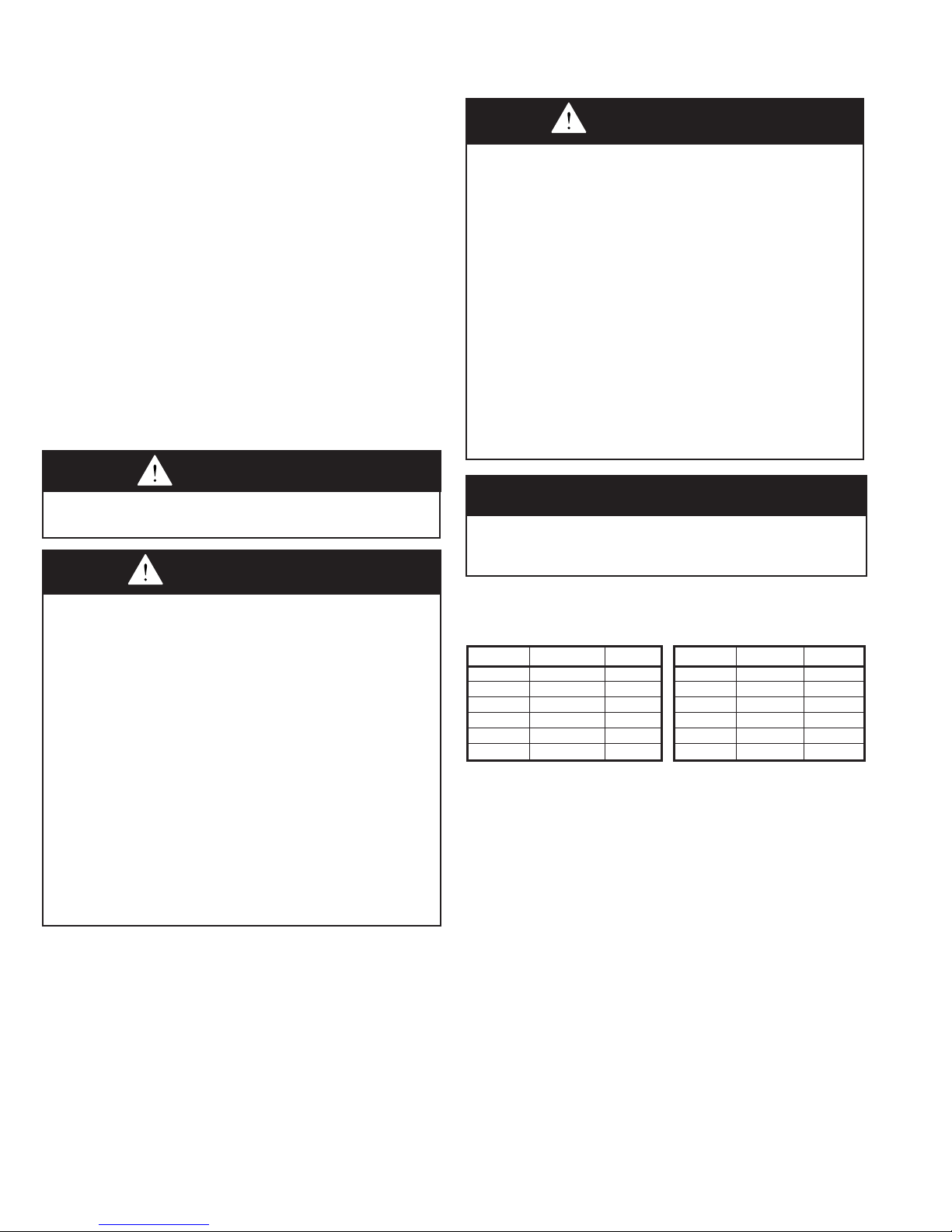
In locating units, consider general space-heating requirements
of the area. Unit heaters should be located so they discharge
air nearly parallel to exposed walls. Arrange units so they do
not blow directly at occupants. Interference of air streams by
columns, beams, partitions, or other obstructions should be
avoided as much as possible.
In multiple unit installations, arrange units so that each supports
the air stream of the next unit, thus creating circulatory air
movement in the area. See Figure 3.1. A large portion of the
heated air should be directed toward the side of the building
exposed to prevailing winds.
Height at which unit heaters are installed is critical. Maximum
mounting heights for all units are listed in Table 6.2. The
maximum mounting height for any unit is that height above
which the unit will not deliver heated air to the floor. The
maximum mounting heights must not be exceeded in order to
assure maximum comfort.
heater above the maximum mounting height shown in Table 6.2
or below eight feet. Two tapped holes (3/8" - 16) in the top of the
unit are provided for unit heater suspension. Suspension can
be made with threaded rods, pipes, or ceiling hanger brackets
furnished by others. See Figure 6.1 for hanger hole locations
and Figure 3.3 for suspension methods.
NOTE: A pipe hanger adapter kit, shown in Figure 3.3 is
available as an accessory from Modine, or can be selffabricated. Kit consists of two drilled 3/4" I.P.S. pipe caps and
two 3/8" - 16 x 1-3/4" capscrews to facilitate threaded-pipe
suspension. One kit is required for mounting each unit.
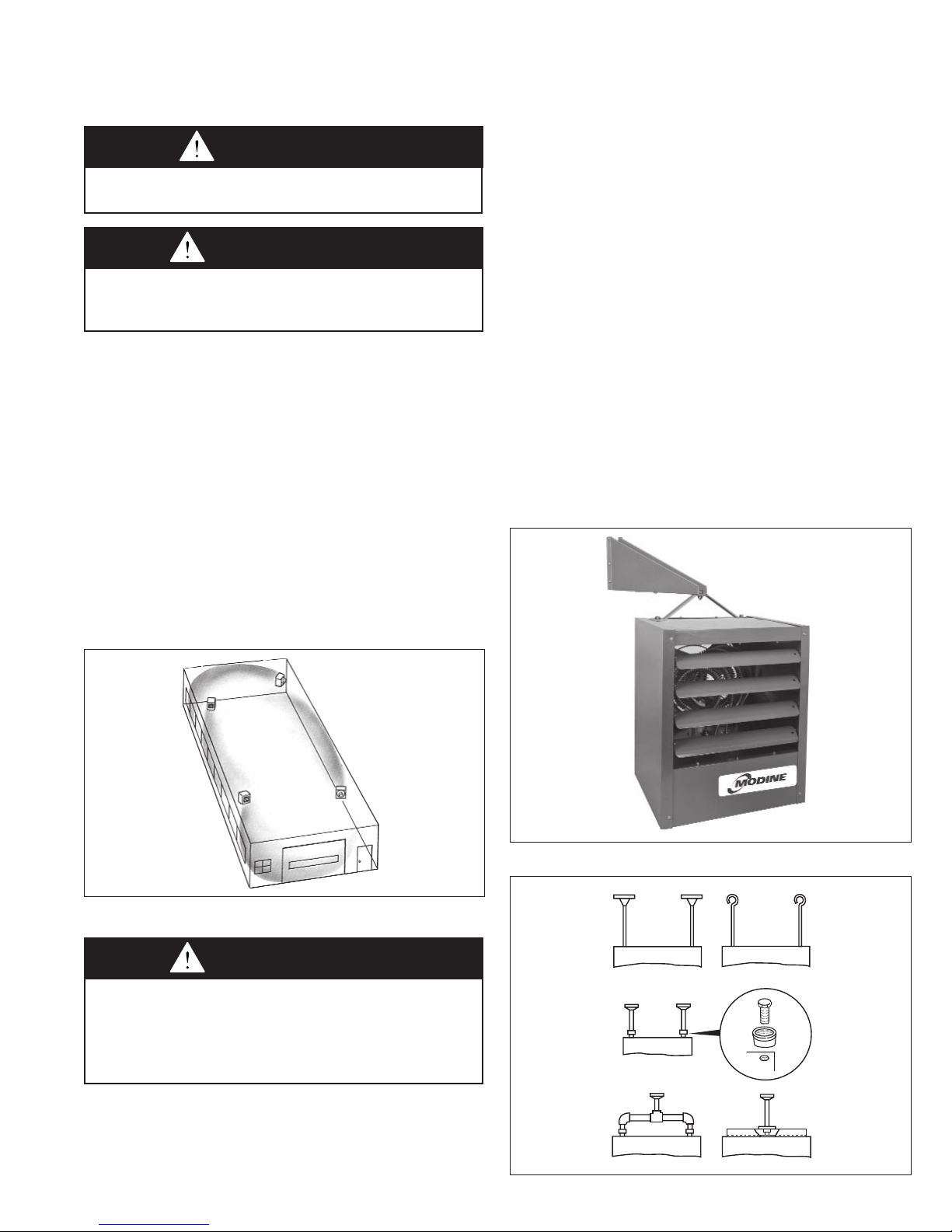
Wall-Mounting Bracket
For easier installation of Model HER electric unit heaters, where
ceiling suspension is not feasible, a wall-mounting bracket kit is
available. The bracket saves installation time, has a built-in wall
clearance, and provides an inexpensive and convenient wall
mounting method. The one-point suspension, shown in Figure
3.2, permits swiveling the unit 90 degrees horizontally for most
effective air direction. Refer to separate bulletin furnished with
the kit for bracket assembly and installation. Refer to
Table 6.2 for maximum mounting height. Minimum mounting
height is eight feet.
Figure 3.1 - Typical Unit Locations
Figure 3.1 - Typical Unit Locations
UNIT MOUNTING
CAUTION
1. Do not install appliance closer than 12 inches to
combustible materials in any direction.
2. The bottom of the appliance must be at least 8 feet above
the floor.
3. Do not attach duct work, air filters, or polytubes to any
appliance.
Figure 3.3 - Ceiling Suspension Methods
It is recommended that adequate service access in excess of 18
inches be provided for the motor and fan.
Be sure the means of suspension is adequate to support the
weight of the unit (see note). Clearances to combustibles as
specified above must be strictly maintained. Do not install unit
2-525.3
3
3
 Loading...