

Modine Manufacturing HD60, HD45, HD75, HD100, HD125 Installation And Service Manual
...
INSTALLATION AND SERVICE MANUAL
separated combustion gas-fired unit heaters
WARNING
1. Improper installation, adjustment, alteration,
service or maintenance can cause property
damage, injury or death, and could cause
exposure to substances which have been
determined by various state agencies
to cause cancer, birth defects or other
reproductive harm. Read the installation,
operating and maintenance instructions
thoroughly before installing or servicing this
equipment.
2. Do not locate ANY gas-fired units in areas
where chlorinated, halogenated, or acid
vapors are present in the atmosphere. These
substances can cause premature heat
exchanger failure due to corrosion, which
can cause property damage, serious injury,
or death.
FOR YOUR SAFETY
WHAT TO DO IF YOU SMELL GAS:
1. Open windows.
2. Do not try to light any appliance.
3. Do not touch any electrical switch; do
not use any phone in your building.
4. Immediately call your gas supplier
from a neighbor’s phone. Follow the gas
supplier’s instructions. If you can not reach
your gas supplier, call your fire department.
6-584.2
5H80002A Rev. B
March, 2009
model HDS and HDC
All models approved for use in California by the CEC, in New
York city by the MEA division, and in Massachusetts. Unit heater
is certified for residential and commercial applications.
FOR YOUR SAFETY
The use and storage of gasoline or other
flammable vapors and liquids in open containers
in the vicinity of this appliance is hazardous.
IMPORTANT
The use of this manual is specifically intended
for a qualified installation and service agency.
All installation and service of these units must
be performed by a qualified installation and
service agency.
Inspection on Arrival
1. Inspect unit upon arrival. In case of damage, report it
immediately to transportation company and your local
Modine sales representative.
2.
Check rating plate on unit to verify that power supply meets
available electric power at the point of installation.
3. Inspect unit upon arrival for conformance with description of
product ordered (including specifications where applicable).
Table of Contents
Inspection on Arrival. . . . . . . . . . . . . . . . . . . . . . . . . . . . . . . . . 1
Special Precautions . . . . . . . . . . . . . . . . . . . . . . . . . . . . . . . . . 2
SI (Metric) Conversion Factors. . . . . . . . . . . . . . . . . . . . . . . . . 3
Before you Begin . . . . . . . . . . . . . . . . . . . . . . . . . . . . . . . . . . . 3
Unit Location. . . . . . . . . . . . . . . . . . . . . . . . . . . . . . . . . . . . . . . 4
Combustible Material and Service Clearances
Unit Mounting
Venting
Gas Connections
Electrical
Operation
Unit Components . . . . . . . . . . . . . . . . . . . . . . . . . . . . . . . . . . 15
Dimensions. . . . . . . . . . . . . . . . . . . . . . . . . . . . . . . . . . . . . . . 16
Service/Trouble Shooting . . . . . . . . . . . . . . . . . . . . . . . . . . . . 17
Unit Wiring Diagram . . . . . . . . . . . . . . . . . . . . . . . . . . . . . . . . 18
Serial/Model Number/Replacement Parts . . . . . . . . . . . . . . . 19
Commercial Warranty. . . . . . . . . . . . . . . . . . . . . . . . . . . . . . . 20
. . . . . . . . . . . . . . . . . . . . . . . . . . . . . . . . . . 5
. . . . . . . . . . . . . . . . . . . . . . . . . . . . . . . . . . . . . . . 6
. . . . . . . . . . . . . . . . . . . . . . . . . . . . . . . 12
. . . . . . . . . . . . . . . . . . . . . . . . . . . . . . . . . . . . . 13
. . . . . . . . . . . . . . . . . . . . . . . . . . . . . . . . . . . . . 14
. . . . . . . . . 4
PLEASE BE SURE TO LEAVE IT WITH THE OWNER WHEN YOU LEAVE THE JOB.
THIS MANUAL IS THE PROPERTY OF THE OWNER.
SPECIAL PRECAUTIONS
SPECIAL PRECAUTIONS
THE INSTALLATION AND MAINTENANCE INSTRUCTIONS IN THIS
MANUAL MUST BE FOLLOWED TO PROVIDE SAFE, EFFICIENT
AND TROUBLE-FREE OPERATION. IN ADDITION, PARTICULAR
CARE MUST BE EXERCISED REGARDING THE SPECIAL
PRECAUTIONS LISTED BELOW. FAILURE TO PROPERLY ADDRESS
THESE CRITICAL AREAS COULD RESULT IN PROPERTY DAMAGE
OR LOSS, PERSONAL INJURY, OR DEATH. THESE INSTRUCTIONS
SUBJECT TO ANY MORE RESTRICTIVE LOCAL OR NATIONAL
CODES.
HAZARD INTENSITY LEVELS
1. DANGER: Indicates an imminently hazardous situation
which, if not avoided, WILL result in death or serious injury.
2. WARNING
which, if not avoided, COULD result in death or serious injury.
3. CAUTION: Indicates a potentially hazardous situation which,
if not avoided, MAY result in minor or moderate injury.
4. IMPORTANT: Indicates a situation which, if not avoided,
MAY result in a potential safety concern.
: Indicates a potentially hazardous situation
dANGER
Appliances must not be installed where they may be exposed
to a potentially explosive or flammable atmosphere.
WARNING
1. Gas fired heating equipment must be vented - do not
operate unvented.
2. A built-in power exhauster is provided - additional external
power exhausters are not required or permitted.
3. If you are replacing an existing heater, it may be necessary
to resize the venting systems. Improperly sized venting
systems can result in vent gas leakage or the formation of
condensate. Refer to the National Fuel Gas Code ANSI
Z223.1 or CSA B149.1 latest edition. Failure to follow these
instructions can result in injury or death.
4. Under no circumstances should two sections of double wall
vent pipe be joined together within one horizontal vent system
due to the inability to verify complete seal of inner pipes.
5. All field gas piping must be pressure/leak tested prior to
operation. Never use an open flame. Use a soap solution
or equivalent for testing.
6. Gas pressure to appliance controls must never exceed 14"
W.C. (1/2 psi).
7. To reduce the opportunity for condensation, the minimum
sea level input to the appliance, as indicated on the serial
plate, must not be less than 5% below the rated input,
or 5% below the minimum rated input of dual rated units.
8. Disconnect power supply before making wiring connections
to prevent electrical shock and equipment damage.
9. All appliances must be wired strictly in accordance with
wiring diagram furnished with the appliance. Any wiring
different from the wiring diagram could result in a hazard to
persons and property.
10. Any original factory wiring that requires replacement must
be replaced with wiring material having a temperature
rating of at least 105°C.
11. Ensure that the supply voltage to the appliance, as indicated
on the serial plate, is not 5% greater than the rated voltage.
12. When servicing or repairing this equipment, use only
factory-approved service replacement parts. A complete
replacements parts list may be obtained by contacting
the factory. Refer to the rating plate on the appliance for
complete appliance model number, serial number, and
company address. Any substitution of parts or controls not
approved by the factory will be at the owners risk.
cAUTION
1. All literature shipped with this unit should be kept for
future use for servicing or service diagnostics. Do not
discard any literature shipped with this unit.
2. Consult piping, electrical, and venting instructions in this
manual before final installation.
3. Do not attach ductwork, air filters, or polytubes to any
propeller unit heater.
4. Clearances to combustible materials are critical. Be sure to
follow all listed requirements.
5. Low profile heaters are designed for use in heating. applica tions with ambient temperatures between -40°F and 90°F.
6. Do not install unit outdoors.
7.
In garages or other sections of aircraft hangars such
as offices and shops that communicate with areas used for
servicing or storage, keep the bottom of the unit at least
7' above the floor unless the unit is properly guarded
to provide user protection from moving parts. In parking
garages, the unit must be installed in accordance with
the standard for parking structures ANSI/NFPA 88A, and
in repair garages the standard for repair garages NFPA
#88B. In Canada, installation of heaters in airplane
hangars must be in accordance with the requirements
of the enforcing authority, and in public garages in
accordance with the current CSA-B149 codes.
8. In aircraft hangars, keep the bottom of the unit at least 10'
from the highest surface of the wings or engine enclosure
of the highest aircraft housed in the hangars and in
accordance with the requirements of the enforcing authority
and/or NFPA 409-latest edition.
9. Installation of units in high humidity or salt water
atmospheres will cause accelerated corrosion resulting in a
reduction of the normal life of the units.
10. Do not install units below 7' measured from the bottom of
the unit to the floor in commercial applications (unless
unit is properly guarded to provide user protection from
moving parts) and 5' measured from the bottom of the unit
to the floor in residential applications.
11. Be sure no obstructions block air intake and discharge of
unit heaters.
12. The minimum distance from combustible material is based
on the combustible material surface not exceeding 160°F.
Clearance from the top of the unit may be required to be
greater then the minimum specified if heat damage, other
than fire, may occur to materials above the unit heater at
the temperature described.
13. Allow 18" of clearance at rear (or 6" beyond end of motor at
rear of unit, whichever is greater) and access side to
provide ample air for proper operation of fan.
14. Installation must conform with local building codes or in the
absence of local codes, with Part 7, Venting of Equipment,
of the National Fuel Gas Code, ANSI Z223.1 (NFPA 54) -
latest edition. In Canada installation must be in accordance
with CSA-B149.1.
15. The concentric vent adapter box must be installed inside
of the structure or building. Do not install this box on the
exterior of a building or structure.
16. Purging of air from gas supply line should be performed as
described in ANSI Z223.1 - latest edition “National Fuel
Gas Code”, or in Canada in CSA-B149 codes.
17. When leak testing the gas supply piping system, the
appliance and its combination gas control must be isolated
during any pressure testing in excess of 14" W.C. (1/2 psi).
2
6-584.2
SPECIAL PRECAUTIONS / SI (METRIC) CONVERSION FACTORS
BEFORE YOU BEGIN
cAUTION
18. The unit should be isolated from the gas supply piping
system by closing its field installed manual shut-off valve.
This manual shut-off valve should be located within 6' of
the heater.
19. Turn off all gas before installing appliance.
20. Ensure that the supply voltage to the appliance, as
indicated on the serial plate, is not 5% less than the rated
voltage.
21. Check the gas inlet pressure at the unit upstream of the
combination gas control. The inlet pressure should be
6-7" W.C. on natural gas or 12-14" W.C. on propane. If
inlet pressure is too high, install an additional pressure
regulator upstream of the combination gas control.
22. Servicing or repairing of this equipment must be
performed by a qualified service agency.
23. Do not attempt to reuse any mechanical or electronic
ignition controllers which has been wet. Replace defective
controller.
IMPORTANT
1. To prevent premature heat exchanger failure, do not locate
ANY gas-fired appliances in areas where corrosive vapors
(i.e. chlorinated, halogenated or acid) are present in the
atmosphere.
2. To prevent premature heat exchanger failure, the input to
the appliance as indicated on the serial plate, must not
exceed the rated input by more then 5%.
3. To prevent premature heat exchanger failure, observe
heat exchanger tubes. If the bottom of the tubes become
red while blower and furnace are in operation, check to
be sure the blower has been set to the proper rpm for the
application. Refer to page 13 for Blower Adjustments.
4. Start-up and adjustment procedures should be performed
by a qualified service agency.
5.
To check most of the Possible Remedies in the trouble-
shooting guide listed in Table 17.1 refer to the applicable
sections of the manual.
cAUTION
1. All literature shipped with this unit should be kept for future
use for servicing or service diagnostics. Leave manual with
the owner. Do not discard any literature shipped with this unit.
2. Consult piping, electrical, and venting instructions in this
manual before final installation.
3. Do not attach ductwork, air filters, or polytubes to any
propeller unit heater.
In the U.S., the installation of these units must comply with the
“National Fuel Gas Code,” ANSI Z223.1, latest edition (also
known as NFPA 54) and other applicable local building codes.
In Canada, the installation of these units must comply with local
plumbing or waste water codes and other applicable codes and
with the current code CSA-B149.1.
1. All installation and service of these units must be
performed by a qualified installation and service agency
only as defined in ANSI Z223.1, latest edition or in
Canada by a licensed gas fitter.
2. This unit is certified with the controls furnished. For
replacements parts, please order according to the
replacement parts list on serial plate. Always know your
model and serial numbers. The right is reserved to
substitute other authorized controls as replacements.
3. Unit is balanced for correct performance. Do not alter fan
or operate motors at speeds below what is shown in this
manual.
4. Information on controls is supplied separately.
5. The same burner is used for natural and propane gas.
SI (METRIC) CONVERSION FACTORS
To Convert Multiply By To Obtain
"W.C. 0.249 kPa
°F (°F-32) x 5/9 °C
Btu 1.06 kJ
3
Btu/ft
Btu/hr 0.000293 kW
CFH (ft
CFH (ft
CFM (ft
CFM (ft
37.3 kJ/m
3
/hr) 0.000472 m3/min
3
/hr) 0.00000787 m3/s
3
/min) 0.0283 m3/min
3
/min) 0.000472 m3/s
To Convert Multiply By To Obtain
feet 0.305 m
Gal/Hr. 0.00379 m
Gal/Hr. 3.79 l/hr
3
gallons 3.79 l
Horsepower 746 W
inches 25.4 mm
pound 0.454 kg
psig 6.89 kPa
psig 27.7 "W.C.
3
/hr
6-584.2
3

UNIT LOCATION
UNIT LOCATION
dANGER
Appliances must not be installed where they may be exposed
to a potentially explosive or flammable atmosphere.
cAUTION
1. Clearances to combustible materials are critical. Be sure to
follow all listed requirements.
2. Low profile heaters are designed for use in heating applica tions with ambient temperatures between -40°F and 90°F.
3. Do not install unit outdoors.
4. In garages or other sections of aircraft hangars such
as offices and shops that communicate with areas used for
servicing or storage, keep the bottom of the unit at least
7' above the floor unless the unit is properly guarded.
In parking garages, the unit must be installed in accordance
with the standard for parking structures ANSI/NFPA 88A,
and in repair garages the standard for repair garages NFPA
#88B. In Canada, installation of heaters in airplane
hangars must be in accordance with the requirements
of the enforcing authority, and in public garages in
accordance with the current CSA-B149 codes.
5. In aircraft hangars, keep the bottom of the unit at least 10'
from the highest surface of the wings or engine enclosure
of the highest aircraft housed in the hangars and in accor dance with the requirements of the enforcing authority
and/or NFPA 409-latest edition.
6. Installation of units in high humidity or salt water
atmospheres will cause accelerated corrosion resulting in a
reduction of the normal life of the units.
Table 4.1 - Clearances
Unit Side Clearance To Recommended
Combustible Materials Service Clearance
Top and Bottom 1" 1"
Access Side 1" 18"
Non-Access Side 1" 1"
Rear 18" 18"
Vent Connector 4" 4"
6. Do not install units in locations where gas ignition system is
exposed to water spray, rain, or dripping water.
7. Mounting Height (measured from bottom of unit) at which
unit heaters are installed is critical. Refer to mounting
height and heat throw data on page 16 of this manual. The
maximum mounting height for any unit is that height above
which the unit will not deliver heated air to the floor.
Turning The Unit 180° (Model Sizes 30-75 Only)
All units are produced at the factory with left-side controls (when
looking at the unit). If the installation requires the controls to
be on the right side, all HDS/HDC heaters - with the exception
of the 100 and 125 - can be turned-over by following the
instructions below.
• By turning the unit 180° from the way it was received from
the factory, the sides become opposite but the front and
back remain in the same relative position. The bottom panel
now becomes the top panel and vice-versa.
• Remove the access panel, turn it 180°, and re-attach it to
the unit so that all the information labels can be read.
• Remove the spring loaded deflector blades, turn them over,
replace, and adjust so they are open and in a position to
direct the heated air down to the floor.
IMPORTANT
To prevent premature heat exchanger failure, do not locate
ANY gas-fired appliances in areas where corrosive vapors
(i.e. chlorinated, halogenated or acid) are present in the
atmosphere.
Location Recommendations
1. When locating the heater, consider general space and
heating requirements, availability of gas and electrical
supply, and proximity to vent locations.
2. When locating units, it is important to consider that the
combustion air and exhaust vent piping must be connected
to the outside atmosphere. Vent terminals should be located
adjacent to one another. Maximum equivalent vent lengths
are listed in “Section A - General Instruction - All Units” of the
Venting instructions.
3. Be sure the structural support at the unit location site is
adequate to support the unit's weight. For proper operation
the unit must be installed in a level horizontal position.
4. Do not install units in locations where the flue products
can be drawn into the adjacent building openings such as
windows, fresh air intakes, etc.
5. Be sure that the minimum clearances to combustible
materials and recommended service clearances are
maintained. Units are designed for installation with the
minimum clearances as shown in Table 4.1.
4
6-584.2
UNIT MOUNTING
cAUTION
1.
Do not install units below 7' measured from the bottom of
the unit to the floor in commercial applications (unless
unit is properly guarded to provide user protection from
moving parts) and 5' measured from the bottom of the unit
to the floor in residential applications.
2. Be sure no obstructions block air intake and discharge
of unit heaters.
3. The minimum distance from combustible material is
based on the combustible material surface not exceeding
160°F. Clearance from the top of the unit may be required
to be greater than the minimum specified if heat damage,
other than fire, may occur to materials above the unit
heater at the temperature described.
4. Allow 18" clearance at rear (or 6" beyond end of motor
at rear of unit, whichever is greater) and access side to
provide ample air for proper operation of fan.
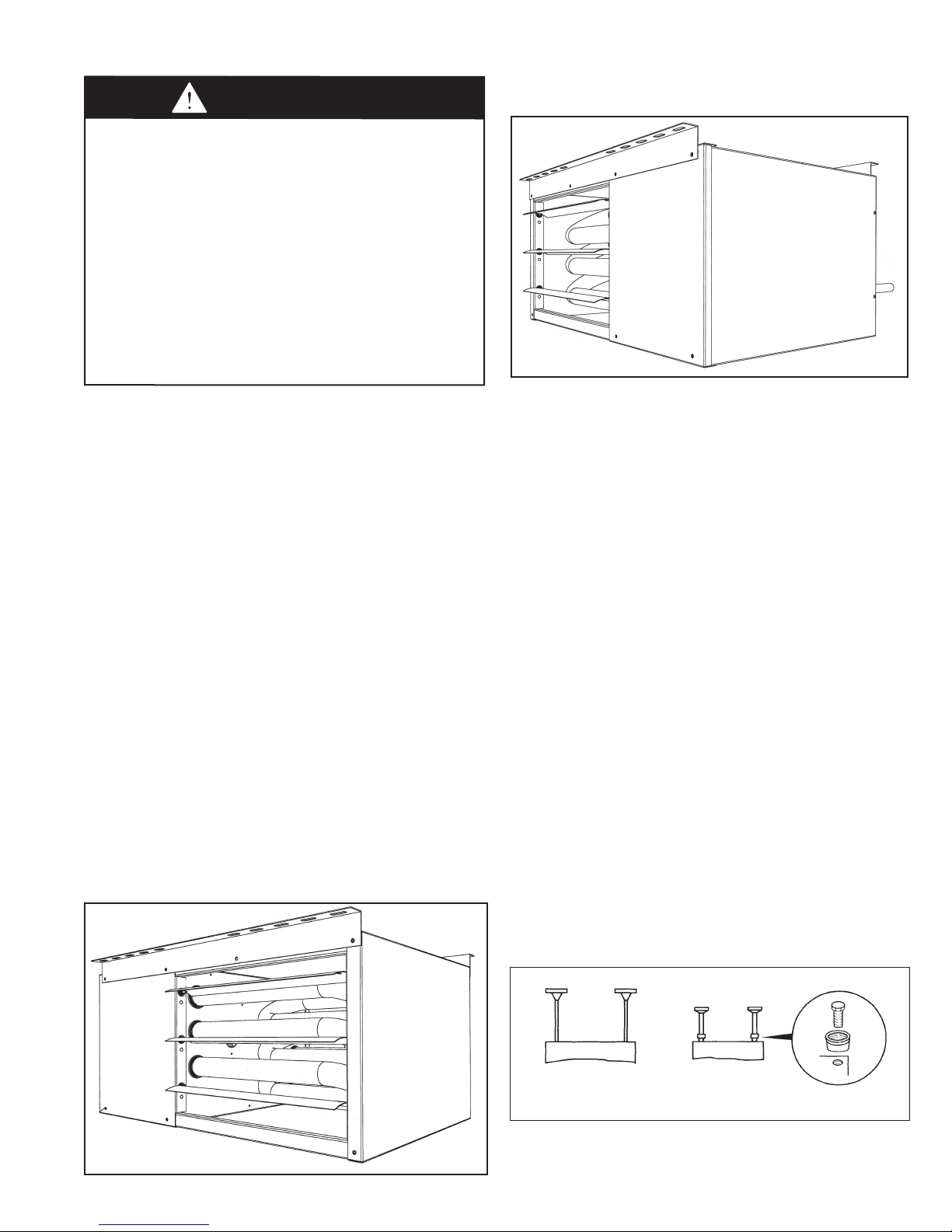
Figure 5.2 - Unit Heater Turned 180° (30-75 units only)
(Access panel and heated air outlet change sides)
1. Be sure the means of suspension is adequate to support
the weight of the unit (see page 16 for unit weights).
2. For proper operation, the unit must be installed in a level
horizontal position.
3. Clearances to combustibles as previously specified must be
strictly maintained.
4. For model sizes 30-75, before lifting the heater for
suspension, the mounting brackets must be installed as
follows (for bracket accessory installation on model sizes
100-125, see the latest revision of literature 6-594):
• For standard (left side) control access, remove the (3)
screws and mounting bracket along the top edge of both
the front and back of the unit. Install the front bracket as
shown in Figure 5.1 by aligning the screw holes on the
bracket with the screw holes on the top edge of the unit.
Repeat for the bracket on the back of the unit.
• For right side control access, remove the (3) screws and
mounting bracket along the top edge of both the front and
back of the unit. Turn the unit over and install the front
bracket as shown in Figure 5.2 by aligning the screw holes
on the bracket with the screw holes on the top edge of the
unit (originally the bottom edge). Repeat for the bracket on
the back of the unit.
5a. Suspension by screws/lag bolts:
brackets to the ceiling joists or truss, using 1/4" screws with
1/2" washers. These unit mounting brackets are slotted to
accommodate joists on 16" or 24" centerlines. See page 16
for mounting bracket dimensions.
Secure the mounting
Figure 5.1 - Unit Heater in Standard Mounting
Configuration (30-75 Units Only)
5b. Suspension by threaded rod:
with threaded rod utilizing the same mounting brackets.
Attach the threaded rod to the unit mounting brackets,
securing with a top and bottom nut. For model sizes
100-125, the units are designed to be suspended by
threaded rod without the use of brackets. On each piece of
3/8" threaded rod used, screw a nut a distance of about one
inch onto the end of the threaded rods that will be screwed
into the unit heater. Place a washer over the end of the
threaded rod and screw the threaded rod into the unit heater
weld nuts on the top of the heater at least 5 turns, and no
more than 10 turns. Tighten the nut first installed onto the
threaded rod to prevent the rod from turning.
Next, drill holes into a steel channel or angle iron at the
same centerline dimensions as those chosen for the heater
being installed. The steel channels or angle iron pieces need
to span and be fastened to appropriate structural members.
Cut the threaded rods to the preferred length, push them
through the holes in the steel channel or angle iron and
secure with washers and lock nuts, lock washers and nuts,
or a washer with double nut arrangement.
NOTE
: A pipe hanger adapter kit, shown in Figure 5.3, is
available as an accessory. One kit consists of two drilled
3/4" IPS pipe caps and two 3/8 - 13 x 1-3/4" capscrews
to facilitate threaded pipe suspension. Two kits would be
required.
5c. Shelf mounted units:
on a shelf. The mounting brackets will need to be attached
to the heater the same manner as explained in note #4,
however, to mount on a shelf the brackets must go on the
bottom of the heater. The brackets must be affixed to the
shelf using similar screws (1/4" screw with 1/2" washer) as
overhead joist or truss mounting. Be sure all clearance to
combustible requirements are met.
The unit heater can also be installed
The unit can also be hung
Figure 5.3 - Unit Heater Suspension Methods
(Threaded Rod) (Pipe Adaptor Kit)
6-584.2
5
INSTALLATION - VENTING
WARNING
1. Gas fired heating equipment must be vented - do not operate
unvented.
2. A built-in power exhauster is provided - additional external
power exhausters are not required or permitted.
3. If you are replacing an existing heater, it may be necessary
to resize the venting systems. Improperly sized venting
systems can result in vent gas leakage or the formation of
condensate. Refer to the National Fuel Gas Code ANSI
Z223.1 or CSA B149.1 latest edition. Failure to follow these
instructions can result in serious injury or death.
4. Under no circumstances should two sections of double wall
vent pipe be joined together within one horizontal vent system
due to the inability to verify complete seal of inner pipes.
cAUTION
Installation must conform with local building codes or in the
absence of local codes, with Part 7, Venting of Equipment, of
the National Fuel Gas Code, ANSI Z223.1 (NFPA 54) - latest
edition. In Canada installation must be in accordance with CSA
B149.1.
Model HDS/HDC unit heaters must be vented with the proper
passageway as described in these instructions to convey
flue gases from the unit or the vent connector to the outside
atmosphere. The heaters must also have a separate combustion
air intake pipe to bring in fresh air for combustion from the
outside atmosphere.
The venting instructions are organized in sections, based on
installation type. The sections are identified as follows:
Instructions Applicable Installation Instructions
Section by Vent System Type
A General instructions for ALL
B VERTICAL 2-PIPE
vent systems ➀
C HORIZONTAL 2-PIPE
D HORIZONTAL AND VERTICAL
CONCENTRIC
➀The differences between Vertical and Horizontal vent systems in 2-Pipe or
Concentric Vent configurations will be identified in “Section A - General
Instructions – All Units”.
vent systems ➀
installations
vent systems ➀
A4. Limit the total equivalent vent pipe length to a minimum
of 3' and a maximum of 25', making the vent system as
straight as possible. The equivalent length of a 3" elbow is
1' and for a 4" elbow is 5'.
A5. A minimum of 12" straight pipe is recommended from the
flue outlet before turns in the vent pipe.
A6. Horizontal sections of vent pipe are to be installed with a
minimum downward slope from the appliance of 1/4 inch
per foot and suspended securely from overhead structures
at points not greater than 3' apart.
A7. Fasten individual lengths of vent together with at least three
corrosion resistant sheet metal screws.
A8. Keep single wall vent pipe at least 6" from combustible
materials. For double wall vent pipe, follow the vent
pipe manufacturer’s clearances to combustibles. The
minimum distance from combustible materials is based
on the combustible material surface not exceeding 160°F.
Clearance from the vent pipe (or the top of the unit) may be
required to be greater than 6" if heat damage other than fire
could result (such as material distortion or discoloration).
A9. Avoid venting through unheated space when possible.
When venting does pass through an unheated space or
if the unit is installed in an environment that promotes
condensation, insulate runs greater than 5' to minimize
condensation. Inspect for leakage prior to insulating and
use insulation that is noncombustible with a rating of not
less than 400°F. Install a tee fitting at the low point of the
vent system and provide a drip leg with a clean out cap as
shown in Figure 8.1.
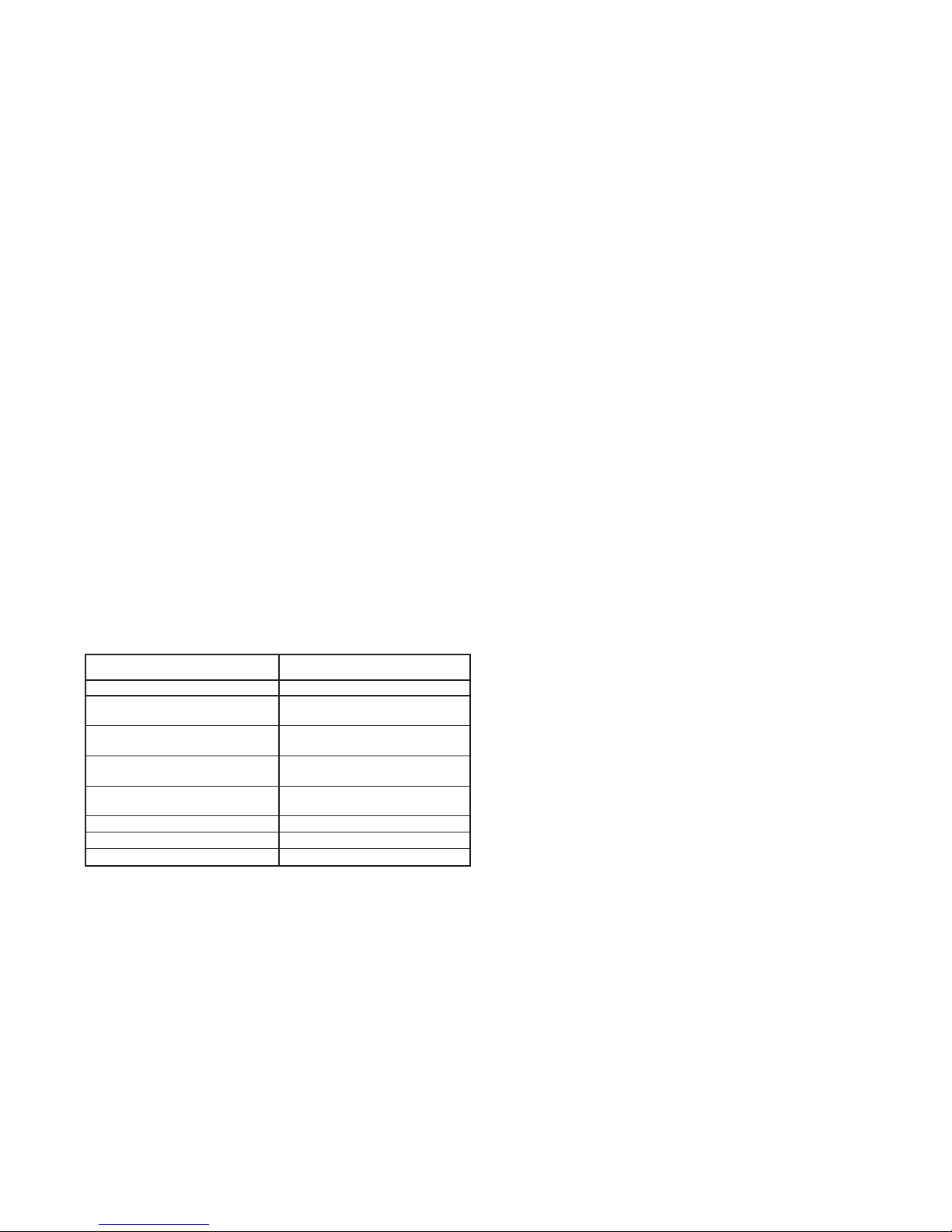
A10. When the vent passes through a combustible INTERIOR
wall or floor, a metal thimble 4" greater than the vent
diameter is necessary. If there is 6' or more of vent pipe
in the open space between the appliance and where the
vent pipe passes through the wall or floor, the thimble need
only be 2" greater than the diameter of the vent pipe. If a
thimble is not used, all combustible material must be cut
away to provide 6" of clearance. Where authorities have
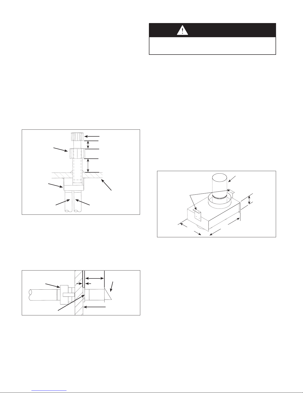
Figure 6.1 - Venting Through Combustible Roof
or Wall
Single Wall Vent Pipe
Flashing
Specified
Terminal
Double Wall Vent Pipe ➀
Flashing
Specified
Terminal
Section A – General Instructions – All Units
A1. If the unit heater being installed is replacing existing
equipment and using the existing vent system from that
equipment, inspect the venting system for proper size and
horizontal pitch, as required in the National Fuel Gas Code
ANSI Z223.1 or CSA B149.1 Installation Code-latest edition
and these instructions. Determine that there is no blockage
or restriction, leakage, corrosion and other deficiencies,
which could cause an unsafe condition.
A2. The vent pipe should be galvanized steel or other suitable
corrosion resistant material. Follow the National Fuel
Gas Code for minimum thickness of vent material. The
minimum thickness for connectors varies depending on the
pipe diameter. Do not vent unit with PVC or other forms of
plastic venting material.
A3. All heaters come with factory installed vent and combustion
air adapters for attaching the vent pipe to the heater (3" for
model sizes 30-45, 4" for model sizes 60-125). Attach the
vent pipe to the adapter with 3 corrosion resistant screws.
(Drill pilot holes through the vent pipe and adapter prior to
screwing in place). Vent pipe must not be smaller than the
connector size.
6
Listed
Thimble
Single
Wall
Single Wall Vent Pipe Terminating
with Double wall vent pipe. ➀
Clearance Specified
by Type B Vent Mfg.
Single Wall Vent Pipe
Listed
Thimble
➀ See Instruction A12 for attaching single wall pipe to double wall pipe
6-584.2
Clearance Specified
by Type B Vent Mfg.
Double
Wall
Specified
Terminal
Single
Wall
Specified
Terminal
INSTALLATION - VENTING
jurisdiction type B vent may be used for the last section
of vent pipe to maintain clearance to combustibles while
passing through wall or floor. See Figure 6.1. Any material
used to close the opening must be noncombustible.
A11. All seams and joints of the single wall pipe must be sealed
with metallic tape or silastic suitable for temperatures up to
400°F. Wrap the tape two full turns around the vent pipe.
One continuous section of double wall vent pipe may be
used within the vent system. Refer to instruction A12 in
“Section A – General Instructions – All Units” for attaching
double wall pipe to single wall pipe.
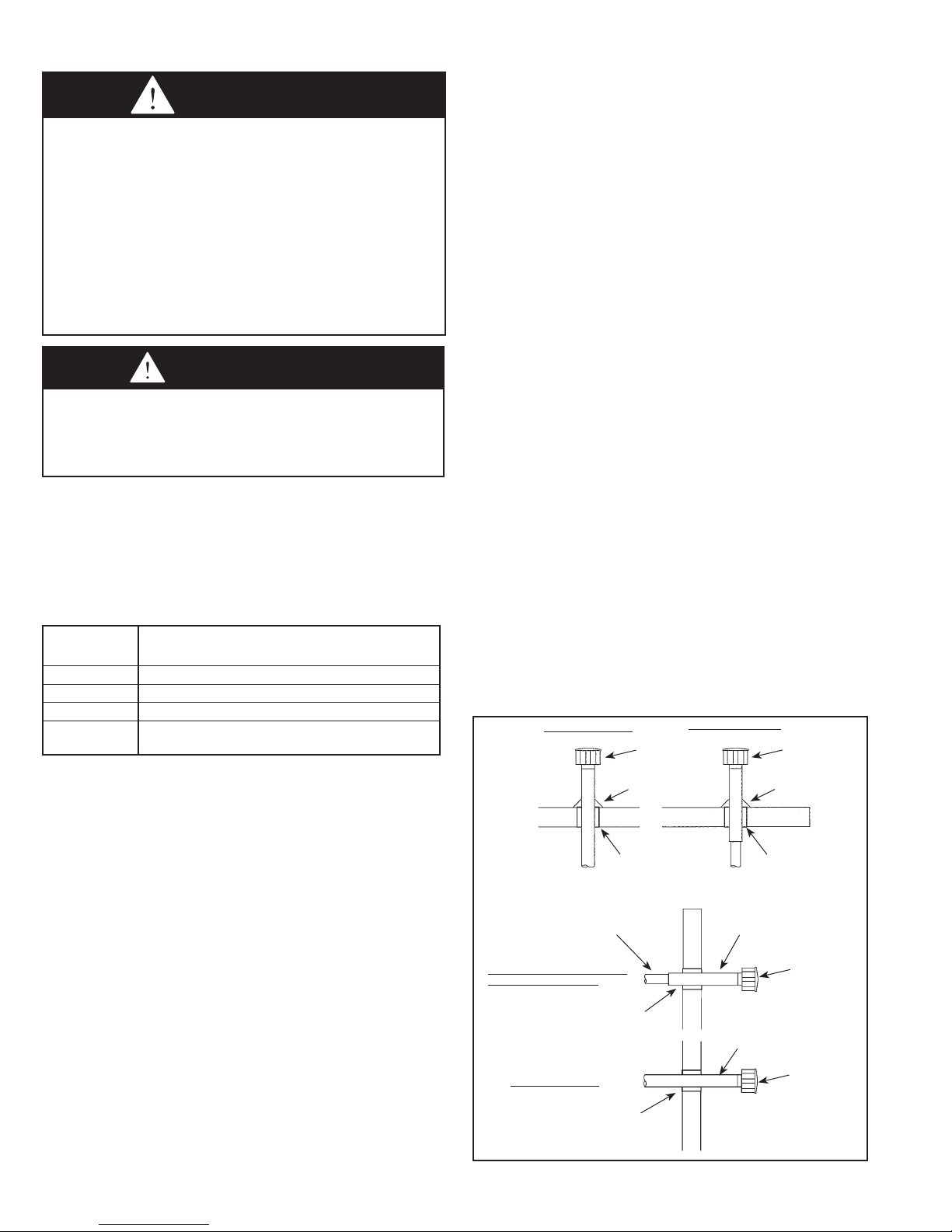
A12. The following are General Instructions for Double Wall
(Type B) Terminal Pipe Installation:
How to attach a single wall vent terminal to double wall
(type B) vent pipe:
1. Look for the “flow” arrow on the vent pipe.
2. Slide the vent terminal inside the exhaust end of the
double wall vent pipe.
3. Drill (3) holes through the pipe and the vent terminal.
Using 3/4" long sheet metal screws, attach the cap to
the pipe. Do not over tighten.
How to connect a single wall vent system to a double
wall (type B) vent pipe:
1. Slide the single wall pipe inside the inner wall of the
double wall pipe.
2. Drill (3) holes through both walls of the single and
double wall vent pipes. Using 3/4" sheet metal screws,
attach the two pieces of pipe. Do not over tighten.
3. The gap between the single and double wall pipe must
be sealed but it is not necessary to fill the full volume
of the annular area. To seal, run a large bead of 400°F
silastic around the gap.
A13. Vent termination clearances must be maintained:
Table 7.1 - Vent Termination Clearances
Minimum Clearances for
Structure Vent Terminal Location
Forced air inlet within 10 feet 3 feet above
Combustion air inlet of another
appliance 6 feet all directions
Door, window, gravity air inlet, 4 feet horizontal and below
or any building opening 1 foot above
Electric meter, gas meter, gas 4 feet horizontal (U.S.)
regulator, and relief equipment ➀ 6 feet horizontal (Canada)
Gas regulator ➀ 3 feet horizontal (U.S.)
6 feet horizontal (Canada)
Adjoining building or parapet wall 6 feet all directions
Adjacent public walkways 7 feet all directions
Grade (ground level) 3 feet above
➀
Do not terminate the vent directly above a gas meter or regulator.
➁
The vent must be at least 6" higher than anticipated snow depth.
➁
A20. Long runs of horizontal or vertical combustion air pipes
may require insulation in very cold climates to prevent the
buildup of condensation on the outside of the pipe where
the pipe passes through conditioned spaces.
A21. Vertical combustion air pipes should be fitted with a tee
with a drip leg and a clean out cap to prevent against the
possibility of any moisture in the combustion air pipe from
entering the unit. The drip leg should be inspected and
cleaned out periodically during the heating season.
A22. In addition to following these General Instructions, specific
instructions for Vertical and Horizontal vent systems in
2-Pipe or Concentric Vent configurations must also be
followed. The following outlines the differences:
Vertical Vent System Determination
• Vertical vent systems terminate vertically (up) (an example is
shown in Figure 8.1).
• Determine the venting configuration as follows:
> For two building penetrations through the wall or roof (one
for the combustion air inlet pipe and one for the vent pipe),
proceed to “Section B - Vertical 2-Pipe Venting”.
> For a single larger building penetration through the wall or
roof, through which both the combustion air inlet and vent
pipes will pass, proceed to “Section D - Horizontal and
Vertical Concentric Venting”.
> For all other cases, proceed to the next section for
Horizontal Vent System Determination.
Horizontal Vent System Determination
• Horizontal vent systems terminate horizontally (sideways)
(an example is shown in Figure 9.1).
• Determine the venting configuration as follows:
> For two building penetrations through the wall or roof (one
for the combustion air inlet pipe and one for the vent pipe),
proceed to “Section C - Horizontal 2-Pipe Venting”.
> For a single larger building penetration through the wall or
roof, through which both the combustion air inlet and vent
pipes will pass, proceed to “Section D - Horizontal and
Vertical Concentric Venting”.
A14. Do NOT vent this appliance into a masonry chimney.
A15. Do NOT use dampers or other devices in the vent or
combustion air pipes.
A16.
The venting system must be exclusive to a single
appliance, and no other appliance is allowed to be vented
into it.
A17. Precautions must be taken to prevent degradation of
building materials by flue products.
A18. Single wall vent pipe must not pass through any
unoccupied attic, inside wall, concealed space, or floor.
A19. Uninsulated single wall vent pipe must not be used
outdoors for venting appliances in regions where the 99%
winter design temperature is below 32°F.
6-584.2
7
INSTALLATION - VENTING
"H" MIN*
12" MIN
RECOMMENDED
4" MIN
ROOF PITCH IS:
X / 12
MINIMUM DISTANCE TO ADJOINING WALL
OR BUILDING IS 2 FEET.
REFER TO TABLE 8.1 FOR "H" DIMENSION.
"H" MIN*
(SEE TABLE 8.1)
TEE WITH DRIP LEG
AND CLEANOUT CAP
(SLOPE 1/4" PER
FOOT DOWNWARD
TOWARD DRIP LEG)
COMBUSTION AIR
ROOF FLASHING
USE LISTED THIMBLE
THROUGH ROOF AND
CEILING
EXHAUST
USE LISTED THIMBLES
THROUGH CEILING
AND ROOF
12
X
ROOF FLASHING
COMBUSTION AIR
EXHAUST
TEE WITH DRIP LEG
AND CLEANOUT CAP
SPECIFIED
TERMINAL
SPECIFIED
TERMINAL
"H" MIN*
(SEE TABLE 8.1)
"H" MIN*
(SEE TABLE 8.1)
Combustion Air
Exhaust
* SIZE ACCORNING
TO EXPECTED
SNOW DEPTH.
TO WALL OR ADJOINING BUILDING
12" MIN
12" MIN*
2' MIN
6" MIN
USE THIMBLE
THROUGH
CELLING
TEE WITH DRIP LEG
AND CLEANOUT CAP
ROOF FLASHING
TERMINAL
TERMINAL
Section B – Vertical 2-Pipe Vent System
Installation
B1. This section applies to vertically vented 2-pipe (one
combustion air inlet pipe and one vent pipe) vent systems
and is in addition to “Section A – General Instructions – All
Units”.
B2. Vertical vent systems terminate vertically (up).
B3. It is recommended to install a tee with drip leg and clean out
cap as shown in Figure 8.1.
B4. The combustion air and vent pipes must be terminated with
(2) Gary Steel Model 1092 caps.
B5. Vertical vents must terminate a minimum horizontal and
vertical distance from roof lines and adjacent walls or
obstructions. These minimum distances are outlined in
Figure 8.1 and Table 8.1.
B6. The vent must terminate at least 1 foot above and 6 inches
horizontally from the combustion air inlet.
Figure 8.1 - Vertical 2-Pipe Vent System - Sloped Roof
Table 8.1 - Minimum Height from Roof to Lowest
Discharge Opening
Rise X (in) Roof Pitch Min Height H (ft) ➀
0-6 Flat to 6/12 1.00
6-7 6/12 to 7/12 1.25
7-8 7/12 to 8/12 1.50
8-9 8/12 to 9/12 2.00
9-10 9/12 to 10/12 2.50
10-11 10/12 to 11/12 3.25
11-12 11/12 to 12/12 4.00
12-14 12/12 to 14/12 5.00
14-16 14/12 to 16/12 6.00
16-18 16/12 to 18/12 7.00
18-20 18/12 to 20/12 7.50
20-21 20/12 to 21/12 8.00
➀ Size according to expected snow depth.
Figure 8.2 - Vertical 2-Pipe Vent System - Flat Roof
B9. Once venting is complete, proceed section titled “Installation
– Gas Connections”.
8
6-584.2
INSTALLATION - VENTING
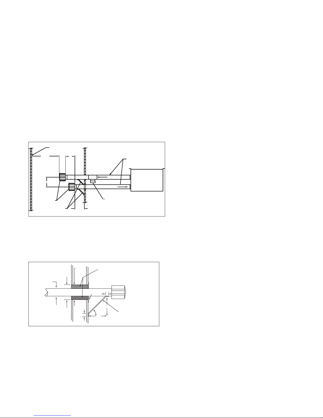
METAL
SLEEVE
FIBER GLASS
INSULATION
MIN. 2"
2" MIN.
VENT TERMINATION
SUPPORT BRACKET
(where required)
(Make from 1" x 1" steel angle)
9"
9"
45°
1"
METAL
SLEEVE
2" MIN.
VENT PIPE
DIAMETER
METAL FACE
PLATE
1"
COMBUSTION AIR
EXHAUST
SLOPE 1/4" PER FOOT
DOWNWARD FROM UNIT
TEE WITH DRIP LEG AND
CLEANOUT CAP AT LOW
POINT OF VENT SYSTEM
SPECIFIED
TERMINAL
SUPPORT BRACKET
6" MIN
2' MIN
4" MIN
12"
ADJACENT
BUILDING
Section C – Horizontal 2-Pipe Vent System
Installation
C1. This section applies to horizontally vented 2-pipe
vent systems (one combustion air inlet pipe and one
vent pipe) and is in addition to “Section A – General
Instructions – All Units”.
C2. Horizontal vent systems terminate horizontally
(sideways).
C3. All horizontal vents must be terminated with a Gary Steel
1092 vent cap. The cap must terminate a minimum
distance from the external wall, as summarized in
Figure 9.1.
C4
. The termination of horizontally vented system must
extend 16 inches beyond the exterior surface of an
exterior wall.
C5
. The combustion air pipe must be a minimum of 6 inches
below the vent pipe, and 4 inches from the exterior wall.
C6. Construct the vent system as shown in Figure 9.1.
Figure 9.1 - Horizontal Venting with Downward Pitch
C11. For a vent termination located under an eave, the
distance of the overhang must not exceed 24". The
clearance to combustibles above the exterior vent
must be maintained at a minimum of 12". Consult the
National Fuel Gas Code for additional requirements for
eaves that have ventilation openings.
C12. Once venting is complete, proceed section titled
“Installation – Gas Connections”.
C7
. When horizontal vents pass through a combustible
wall (up to 22 inches thick), the vent passage must be
constructed and insulated as shown in Figure 9.2.
C8. The vent must be supported as shown in Figure 9.2.
Figure 9.2 - Exhaust Vent Construction Through
Combustible Walls and Support Bracket
C9. When condensation may be a problem, the vent system
shall not terminate over public walkways or over an area
where condensate or vapor could create a nuisance
or hazard or could be detrimental to the operation of
regulators, relief openings, or other equipment.
C10. Maintain a 1/4" per foot downward slope away from the
heater and place a drip leg with clean out near the exit of
the vent as shown in Figure 9.1, or allow the condensate
to drip out the end.
6-584.2
9
INSTALLATION - VENTING
Section D – Concentric Vent System
Installation
D1.
This section applies to both horizontally and vertically
vented concentric vent systems as defined in “Section A
– General Instructions – All Units”, and is in addition to the
instructions in that section.
D2. When utilizing the concentric vent option, it should have
been predetermined whether the appliance will be
horizontally or vertically vented. Before proceeding, verify
that the concentric vent kit received contains the correct
components for the installation:
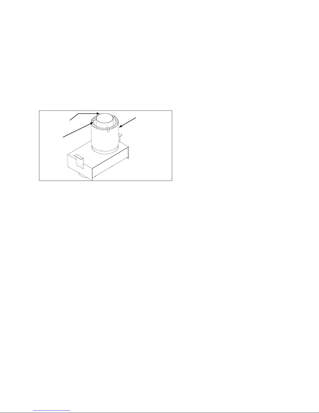
For Vertically Vented Units (Refer to Figure 10.1):
➀ Concentric adapter assembly (same for horizontal and
vertical kits)
➁ Standard Gary Steel 1092 vent termination
➂ Specially designed inlet terminal (part #5H75154B1)
Figure 10.1 - Vertical Concentric Vent Kit
Components
Outlet Vent
Combustion Air
Inlet Terminal
Concentric
Vent Adapter
Box
4" Combustion Air 4" Exhaust
6" Min.
12" Min.*
Termination Cap
* Size according
to expected
snow depth.
Building
Roof / Ceiling
cAUTION
The concentric vent adapter box must be installed inside of
the structure or building. Do not install this box on the exterior
of a building or structure.
D3. Once the kit contents have been verified as correct for the
direction of venting, the concentric vent adapter box is to
be installed. Determine the location of the box. Be sure to
maintain all clearances as listed in these instructions.
D4. The adapter box is to be mounted on the interior side of the
building. It must not be mounted outside the building.
D5. The adapter box can be mounted flush to the wall (for
horizontal kits) or to the ceiling (for vertical kits). The box
can also be offset from the wall or ceiling by using field
supplied brackets. When mounting the box, consider
serviceability and access to the vent and combustion air
pipes.
D6. If the box is to be mounted using field supplied brackets,
these brackets must be strong enough to rigidly secure
the box to the wall or ceiling, and should be made from
corrosion resistant material. After determining the length of
the field supplied brackets, attach them to the sides of the
box using several corrosion resistant sheet metal screws.
See Figure 10.3 for typical installation and brackets.
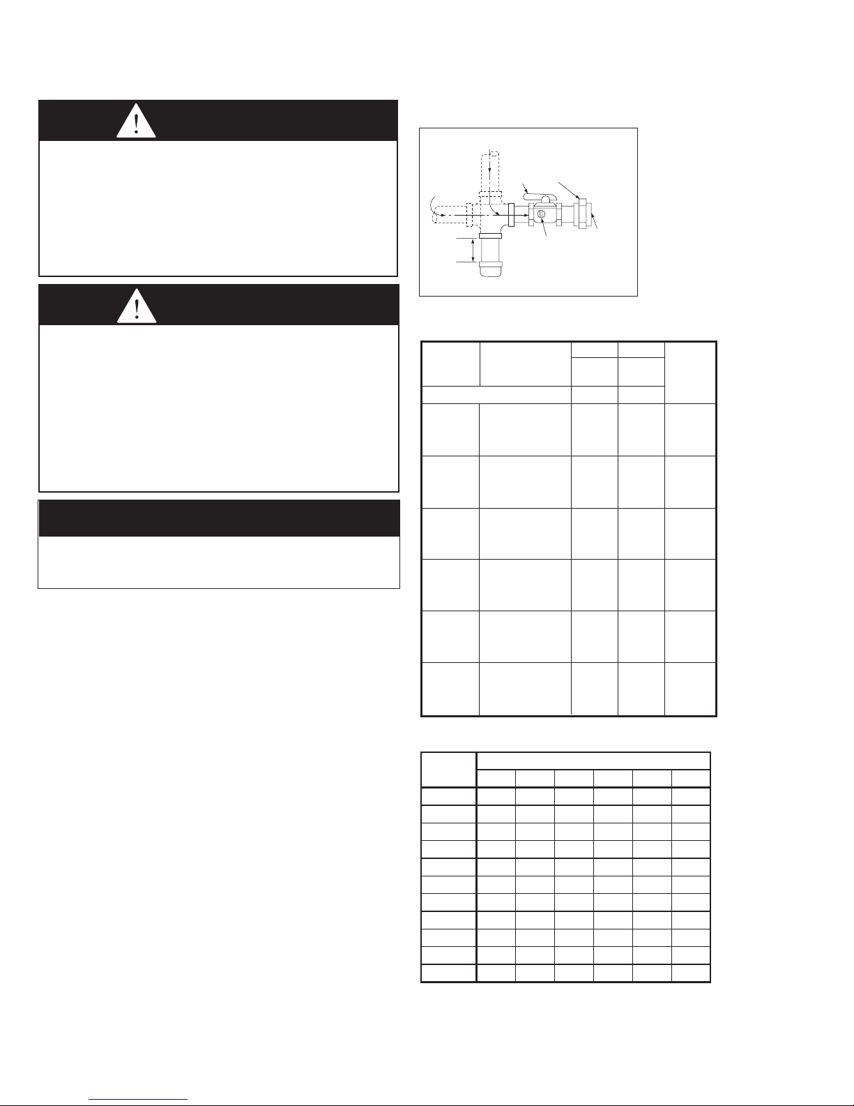
Figure 10.3 - Adapter Box with Outlet Vent Pipe
Attached
4" Outlet Vent Pipe
Attached
Field Supplied
Mounting Brackets
4"
For Horizontally Vented Units (Refer to Figure 10.2):
➀ Concentric adapter assembly (same for horizontal and
vertical kits)
➁ Special vent termination cap (part #5H75150B1)
➂ Special inlet air guard
Figure 10.2 - Horizontal Concentric Vent Kit
Components
Concentric
Vent Adapter
Box
Combustion Air
Intake Guard
14" Min.
1" Min.
Outlet Vent
Termination Cap
Building Side Wall
8.25"
11.75"
D7. Determine the length of the vent pipe and combustion
air pipe that must be attached to the vent outlet and
combustion air inlet (on the concentric side) of the adapter
box (refer to Figure 10.3 and 11.1) to extend through the
building wall or roof. Be sure to add the length of the field
supplied brackets (if used) and the thickness of the wall or
roof. Note the following when determining the pipe lengths:
For Vertical Concentric Vent Kits
(refer to Figure 10.1):
• The bottom of the combustion air intake pipe must
terminate above the snow line, or at least 12 inches above
the roof, whichever distance is greater.
• The bottom of the vent cap must terminate at least 6 inches
above the top of the combustion air intake cap.
For Horizontal Concentric Vent Kits
(refer to Figure 10.2):
• The combustion air intake pipe must terminate at least
1 inch from the wall to prevent water from running down
the wall and into the pipe.
• The back of the vent cap must terminate at least 14 inches
from the combustion air intake pipe.
10
6-584.2
D8. Cut the concentric side vent and combustion air pipes to
the proper length as determined in the previous step. Note
that the vent pipe diameter is 4" and the combustion air
intake pipe diameter is 6". Both pipes must be single wall
galvanized or stainless steel material.
D9. Attach the concentric side vent pipe to the vent outlet
of the concentric vent adapter box, as shown in Figure
10.3, using at least 3 corrosion resistant sheet metal
screws. Seal the joint and seam using sealant suitable for
temperatures up to 400°F.
D10. Slide the combustion air pipe over the vent pipe and attach
to the air inlet of the concentric adapter box, as shown
in Figure 11.1, using at least 3 corrosion resistant sheet
metal screws. Seal the joint and seam using sealant
suitable for temperatures up to 400°F.
Figure 11.1 - Adapter Box with Combustion Air Intake
Pipe Attached
Outlet Vent
Pipe Attached
Combustion Air
Intake Guard
6" Combustion Air
Pipe Attached
D11. Place this assembly (the adapter box, vent pipe and
combustion air pipe) through the wall or roof and verify that
the distance requirements as defined in Step D7 are met.
Securely attach the assembly building.
D12. From outside the building, caulk the gap between the
combustion air intake pipe and the building penetration.
D13. Attach the combustion air intake and vent pipe
terminations as follows:
For Vertical Concentric Vent Kits
(refer to Figure 10.1):
• Slide the combustion air cap down over the vent pipe
and fasten it to the combustion air pipe with at least 3
corrosion resistant sheet metal screws.
• Attach the vent cap to the vent pipe using at least 3
corrosion resistant sheet metal screws.
• Caulk the gap between the combustion air cap and the
vent pipe with silicone sealant, or other appropriate
sealants suitable for metal to metal contact and for
temperatures up to 400° F.
For Horizontal Concentric Vent Kits
(refer to Figure 10.2):
• Attach the combustion air intake guard using corrosion
resistant screws at the end of the combustion air intake
pipe to prevent animals and debris from entering.
• Attach the vent cap to the vent pipe using at least 3
corrosion resistant sheet metal screws.
D14. For model sizes 30 and 45, attach the 3" to 4" vent
transitions on the non-concentric side vent and combustion
air connections using 3 corrosion resistant sheet metal
screws.
D15. Install vent pipe and combustion air pipe between unit
heater and concentric vent adapter box as outlined in
“Section A – General Instructions – All Units”.
D16. Once venting is complete, proceed to the section titled
“Installation - Gas Connections”.
6-584.2
11
INSTALLATION - GAS CONNECTIONS
GAS
SUPPLY LINE
GAS
SUPPLY LINE
GROUND
JOINT
UNION
MANUAL
SHUT-OFF
VALVE
3"
MIN.
SEDIMENT
TRAP
PLUGGED
1/8" NPT TEST
GAGE CONNECTION
TO
CONTROLS
GAS CONNECTIONS
WARNING
1. All field gas piping must be pressure/leak tested prior to
operation. Never use an open flame. Use a soap solution
or equilavent for testing.
2. Gas pressure to appliance controls must never exceed 14"
W.C. (1/2 psi).
3. To reduce the opportunity for condensation, the minimum sea
level input to the appliance, as indicated on the serial plate,
must not be less than 5% below the rated input, or 5% below the
minimum rated input of dual rated units.
cAUTION
1. Purging of air from gas lines should be performed as
described in ANSI Z223.1 - latest edition “National Fuel
Gas Code”, or in Canada CSA-B149 codes.
2. When leak testing the gas supply piping system, the
appliance and its combination gas control must be isolated
during any pressure testing in excess of 14" W.C. (1/2 psi).
3. The unit should be isolated from the gas supply piping
system by closing its field installed manual shut-off
valve.This manual shut-off valve should be located within
6' of the heater.
4. Turn off all gas before installing appliance.
IMPORTANT
To prevent premature heat exchanger failure, the input to the
appliance, as indicated on the serial plate, must not exceed
the rated input by more than 5%.
1. Installation of piping must conform with local building codes,
or in the absence of local codes, with the National Fuel Gas
Code, ANSI Z223.1 (NFPA 54) - latest Edition. In Canada,
installation must be in accordance with CSA-B149.1.
2. Piping to units should conform with local and national
requirements for type and volume of gas handled, and
pressure drop allowed in the line.Refer to Table 12.1 to
determine the cubic feet per hour (CFH) for the type of gas
and size of unit to be installed. Using this CFH value and the
length of pipe necessary, determine the pipe diameter from
Table 12.2. Where several units are served by the same
main, the total capacity, CFH and length of main must be
considered. Avoid pipe sizes smaller than 1/2". Table 12.2
allows for a 0.3" W.C. pressure drop in the supply pressure
from the building main to the unit. The inlet pressure to the
unit must be 6-7" W.C. for natural gas and 11-14" W.C. for
propane gas. When sizing the inlet gas pipe diameter, make
sure that the unit supply pressure can be met after the 0.3"
W.C. has been subtracted. If the 0.3" W.C. pressure drop is
too high, refer to the Gas Engineer’s Handbook for other gas
pipe capacities.
3. Install a ground joint union with brass seat and a manual
shut-off valve adjacent to the unit for emergency shut-off
and easy servicing of controls, including a 1/8" NPT plugged
tapping accessible for test gauge connection (See Figure 12.1).
4. Provide a sediment trap before each unit in the line where
low spots cannot be avoided. (See Figure 12.1).
5. When Pressure/Leak testing, pressures above 14" W.C.
(1/2 psi), close the field installed shut-off valve, disconnect
the appliance and its combination gas control from the gas
supply line, and plug the supply line before testing. When
testing pressures 14" W.C. (1/2 psi) or below, close the
manual shut-off valve on the appliance before testing.
12
Figure 12.1 - Recommended Sediment Trap/Manual
Shut-off Valve Installation - Side or Bottom Gas
Connection ➀
➀ Manual shut-off valve is in the “OFF” position when handle is perpendicular to pipe.
Table 12.1 - Manifold Pressure & Gas Consumption
Natural Propane
Model BTU/Cu. Ft. 1050 2500 No. of
Size Specific Gravity 0.60 1.53 Orifices
Manifold Pressure In. W.C. 3.5 10.0
CFH 28.6 12.0 2
Gal/Hr. Propane .33
30
Sec/cu. ft. 126 300
Orifice Drill Size 49 56
CFH 42.9 18.0 3
Gal/Hr. Propane .50
45
Sec/cu. ft. 84 200
Orifice Drill Size 49 56
CFH 57.1 24.0 4
Gal/Hr. Propane .66
60
Sec/cu. ft. 63 150
Orifice Drill Size 49 56
CFH 71.4 30.0 5
Gal/Hr. Propane .83
75
Sec/cu. ft. 50 180
Orifice Drill Size 49 56
CFH 95.2 40 5
Gal/Hr.Propane 1.09
100
Sec/cu.ft. 38 90
Orifice Drill Size 45 55
CFH 119 50 5
Gal/Hr.Propane 1.37
125
Sec/cu.ft. 30 72
Orifice Drill Size 42 53
Table 12.2 - Gas Pipe Capacities - Natural Gas ➀ ➁
Pipe
Length (ft)
1/2” 3/4” 1” 1-1/4” 1-1/2” 2”
10 132 278 520 1050 1600 3050
20 92 190 350 730 1100 2100
30 73 152 285 590 890 1650
40 63 130 245 500 760 1450
50 56 115 215 440 670 1270
60 50 105 195 400 610 1150
70 46 96 180 370 560 1050
80 43 90 170 350 530 930
100 38 79 150 305 460 870
125 34 72 130 275 410 780
150 31 64 120 250 380 710
➀ Capacities in Cubic Feet per Hour through Schedule 40 pipe with maximum
0.3"W.C. pressure drop with up to 14"W.C. gas pressure. Specific graivity is 0.60
for Natural gas and 1.50 for Propane gas.
➁ For Pipe Capacity with Propane Gas, divide Natural gas capacity by 1.6. Example:
What is the propane gas pipe capacity for 60 feet of 1-1/4" pipe? The Natural gas
capacity is 400 CFH. Divide by 1.6 to get 250 CFH for Propane gas.
Natural Gas
6-584.2
 Loading...