

SELECTION AND INSTALLATION INSTRUCTIONS
model HD/HDB, HDS/HDC, PTS/BTS, and PTC
1. All field gas piping must be pressure/leak tested prior to
operation. Never use an open flame. Use a soap solution
or equivalent for testing.
2. Gas supply shall be shut-off and the electrical power
disconnected before proceeding with the conversion.
Failure to do so could result in fire, explosion or electrical
shock.
WARNING
75-537.7
5H75697B
August, 2009
high altitude orifice kit
Identifying the Model and Control Code
Figure 1.1 explains the model number designations. To be
convertible, the first three characters in the model number must be
HD, HDB, HDS, HDC, PTS, BTS or PTC.
After obtaining this information, refer to the proper selection
chart. The selection charts are differentiated by product type,
altitude and fuel type. If you are converting from natural gas
to propane gas and want to operate at high altitude, both a
propane conversion kit and a propane high altitude kit must
be used. Selection charts include the proper kit suffix, the orifice
drill size, and the number of orifices required for the unit being
converted. Drill sizes are also stamped on each orifice.
IMPORTANT
1. The use of this manual is specifically intended for a
qualified installation and service agency. All installation
and service of these kits must be performed by a qualified
installation and service agency.
2. These instructions must also be used in conjunction with
the Installation and Service manual originally shipped with
the appliance being converted, in addition to any other
accompanying component supplier literature.
Modine gas-fired equipment ratings are certified by CSA or ETL.
For elevations above 2000 ft., ANSI Z223.1 requires ratings be
reduced 4 percent for each 1000 ft. above sea level. For units in
Canada CSA requires that ratings be reduced 10% at elevations
above 2000 ft. The high altitude kits appearing in this bulletin
are for use with units that will be installed over 2000 feet. These
kits comply with both ANSI Z223.1 and CSA requirements.
If a unit is to be installed at higher elevations AND converted
from natural gas to propane gas operation, a propane
conversion kit must be used in conjunction with the high altitude
kit. When converting units to propane at elevations over
2,000 ft., the main burner orifices in the propane conversion
kit must be replaced with the orifices from the “high altitude”
orifice kit. The remaining components of the propane gas kit,
other than the main burner orifices, are required to complete
the conversion to propane gas, regardless of the elevation at
which the unit is installed. For the Selection and Installation
Instructions for propane conversion kits, please see the latest
revision of Modine Bulletin 75-513 for Control Code 34 units
and 75-515 for Control Code 11 and 12 units.
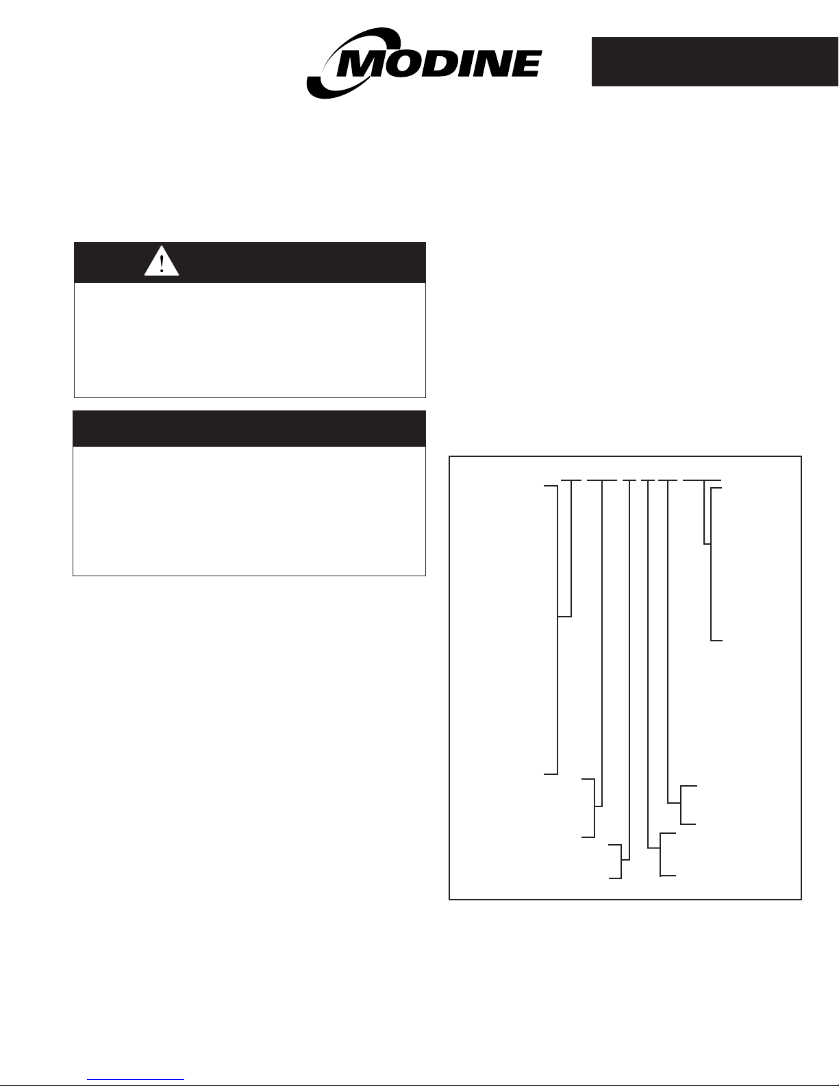
Figure 1.1 - Model Number Designations
HD 45 A S 01 1 1
Model Type
(Tubular HX)
HD - Power Vented
Propeller Unit
(30-125MBH)
HDB - Power Vented
Blower Unit
(60-125MBH)
HDS - Separated
Combustion
Propeller Unit
(30-125MBH)
HDC - Separated
Combustion Blower
Unit (60-125MBH)
PTS - Separated
Combustion Propeller
Unit (150-400MBH)
BTS - Separated
Combustion Blower
Unit (150-400MBH)
PTC - High Efficiency,
Separated Combustion
Propeller Unit
(135-310MBH)
MBH Input
30 - 30,000 Btu/hr input
through
400 - 400,000 Btu/hr input
Heat Exchanger Type
A - Aluminized
S - Stainless Steel
Power Code
01 - 115 volt, 60 hertz,
single phase
Ignition Type
H - Hot Surface
S - Direct Spark
Control Code
11 - Single Stage,
Natural Gas
12 - Two Stage,
Natural Gas
21 - Single Stage,
Propane Gas
22 - Two Stage,
Propane Gas
34 - Single Stage,
Natural Gas
74 - Single Stage,
Propane Gas
PLEASE BE SURE TO LEAVE IT WITH THE OWNER WHEN YOU LEAVE THE JOB.
THIS MANUAL IS THE PROPERTY OF THE OWNER.
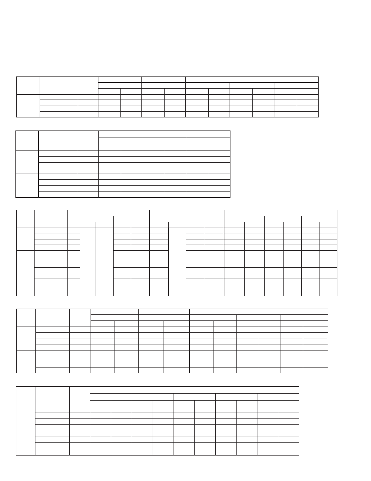
SELECTION OF THE PROPER KIT
Model
Size
Kit Details
Qty per
Kit
U.S.A. and Canada
7501-8000 ft
8001 - 8500 ft
8501-9000 ft
9001 - 9500 ft
9501-10000 ft
NAT
PROP
NAT
PROP
NAT
PROP
NAT
PROP
NAT
PROP
100
Kit Suffix
-
-40
-42
-40
-42
-40
-42
-40
-20
-43
-20
Item Code
-
53184
53213
53184
53213
53184
53213
53184
47336
55576
47336
Orifice
5
49
56
49
56
49
56
49
57
50
57
Pressure Sw
1
Yes
Yes
Yes
Yes
Yes
Yes
Yes
Yes
Yes
Yes
125
Kit Suffix
-
-37
-41
-37
-41
-37
-41
-38
-42
-38
-42
Item Code
-
53178
53212
53178
53212
53178
53212
53182
53213
53182
53213
Orifice
5
45
55
45
55
45
55
46
56
46
56
Pressure Sw
1
Yes
Yes
Yes
Yes
Yes
Yes
Yes
Yes
Yes
Yes
Example: Convert a HDS125AS0112 for at 6000 feet elevation.
The appropriate model size is HDS125 with a Control Code of 12, which is for natural gas. Referring to Tables 2.1 through 3.2, it
can be identified that Table 2.4 should be used as it applies to HDS125 models for the elevation and gas type of this example.
In the column for 5501 - 6500 feet elevation and natural gas, it can be seen that the kit suffix is -30. All conversion kits have the same
base number, only the suffix of the part number changes by model size. The full kit number is 3H035031-30. The Item Code is 53165.
Table 2.1 - High Altitude Kits for HD/HDB 30-75 Models ONLY (7501 ft. and up in Table 2.2)
Model
Size
30-75
Kit Details
Kit Suffix
Item Code - 31669 31671 34503 31671 31669 31671 31669 31672 31670 31673
Orifice
Pressure Sw
Qty per
Kit
- -1 -3 -6 -3 -1 -3 -1 -4 -2 -5
5 51 57 50 57 51 57 51 58 52 59
1 NA NA NA NA NA NA NA NA NA NA
Table 2.2 - High Altitude Kits for HD/HDB 30-75 Models ONLY
Model
Size
30-60
75
Kit Details
Kit Suffix
Item Code
Orifice
Pressure Sw
Kit Suffix
Item Code
Orifice
Pressure Sw
Qty per
Kit
- -2 -5 -7 -11 -9 -13
5 52 59 52 60 53 61
1 NA NA NA NA NA NA
- -2 -5 -8 -12 -10 -14
5 52 59 52 60 53 61
1 NA NA Yes Yes Yes Yes
U.S.A Canada U.S.A. and Canada
2001-4500 ft 2001-4500 ft 4501-5500 ft 5501-6500 ft 6501-7500 ft
NAT PROP NAT PROP NAT PROP NAT PROP NAT PROP
U.S.A. and Canada
7501-8500 ft 8501 - 9500 ft 9501-10000 ft
NAT PROP NAT PROP NAT PROP
31670 31673 45406 45411 45408 45413
31670 31673 45407 45412 45409 45414
Table 2.3 - High Altitude Kits for HDS/HDC 30-75 Models ONLY
Model
Size
30
45
60-75
Kit Details
Kit Suffix
Item Code
Orifice
Pressure Sw
Kit Suffix
Item Code
Orifice
Pressure Sw
Kit Suffix
Item Code
Orifice
Pressure Sw
Qty
per
2001-2500 ft 2501-4500 ft 2001-2500 ft 2501-4500 ft
Kit
NAT PROP NAT PROP NAT PROP NAT PROP
-
5 51 57 50 51 57
1 NA NA NA NA NA
- -15 -16 -6 -15 -17
5 51 51 50 51 57
1 Yes Yes NA Yes Yes
Not Required
- -16 -18 -6 -16 -18
5 51 57 50 51 57
1 Yes Yes NA Yes Yes
U.S.A Canada
-1 -3 -6
31669 31671 34503 31669 31671
47331 47332 34503 47331 47333
Not Required
47332 47334 34503 47332 47334
-1 -3
Not Required
4501-5500 ft 5501-6500 ft 6501-7500 ft
NAT PROP NAT PROP NAT PROP
-16 -18 -21 -22 -23 -26
47332 47334 47337 47338 47339 47342
51 57 51 57 52 59
Yes Yes Yes Yes Yes Yes
-19 -20 -16 -18 -24 -27
47335 47336 47332 47334 47340 47343
51 57 51 57 52 59
Yes Yes Yes Yes Yes Yes
-16 -18 -21 -22 -25 -28
47332 47334 47337 47338 47341 47344
51 57 51 57 52 59
Yes Yes Yes Yes Yes Yes
U.S.A and Canada
Table 2.4 - High Altitude Kits for HD/HDB, HDS/HDC Model Sizes 100 and 125 (7501 ft. and up in Table 2.5)
Model
Size
100
125
Kit Details
Kit Suffix
Item Code
Orifice
Pressure Sw
Kit Suffix
Item Code
Orifice
Pressure Sw
Qty per
Kit
- -32 -44 -31 -44 -32 -44 -33 -36 -39 -42
5 47 1.25mm 46 1.25mm 47 1.25mm 48 56 48 56
1 NA NA NA NA NA NA NA NA Yes Yes
- -29 -34 -29 -34 -29 -34 -30 -35 -37 -41
5 43 54 43 54 43 54 44 54 45 55
1 NA NA NA NA NA NA Yes Yes Yes Yes
U.S.A Canada U.S.A. and Canada
2001-4500 ft 2001-4500 ft 4501-5500 ft 5501-6500 ft 6501-7500 ft
NAT PROP NAT PROP NAT PROP NAT PROP NAT PROP
53170 55577 53166 55577 53170 55577 53171 53177 53183 53213
53164 53172 53164 53172 53164 53172 53165 53176 53178 53212
Table 2.5 - High Altitude Kits for HD/HDB, HDS/HDC Model Sizes 100 and 125
22
75-537.7

SELECTION OF THE PROPER KIT
Table 3.1 - High Altitude Kits for PTS/BTS Models
Model
Size
150
175
200
250
300
350
400
Kit Details
Kit Suffix
Item Code - 55776 55779 55776 55779 55776 55779 55777 55779 55778 55780
Orifice
Pressure Sw
Kit Suffix
Item Code - 55781 55784 55781 55784 55782 55784 55782 55784 55783 55785
Orifice
Pressure Sw
Kit Suffix
Item Code - 55786 55790 55786 55790 55787 55791 55788 55792 55789 55792
Orifice
Pressure Sw
Kit Suffix
Item Code - 55793 55798 55794 55799 55795 55800 55796 55800 55797 55801
Orifice
Pressure Sw
Kit Suffix
Item Code - 55802 55806 55802 55806 55803 55806 55804 55807 55805 55808
Orifice
Pressure Sw
Kit Suffix
Item Code - 55809 55813 55809 55813 55810 55813 55811 55814 55812 55815
Orifice
Pressure Sw
Kit Suffix
Item Code - 55816 55820 55816 55820 55817 55820 55818 55821 55819 55822
Orifice
Pressure Sw
Qty per
Kit
- -45 -48 -45 -48 -45 -48 -46 -48 -47 -49
6 43 54 43 54 43 54 44 54 45 55
1 NA NA NA NA NA NA NA NA NA NA
- -50 -53 -50 -53 -51 -53 -51 -53 -52 -54
7 43 54 43 54 44 54 44 54 45 55
1 NA NA NA NA NA NA NA NA NA NA
- -55 -59 -55 -59 -56 -60 -57 -61 -58 -61
7 41 53 41 53 42 1.50mm 2.35mm 1.45mm 2.30mm 1.45mm
1 NA NA NA NA NA NA NA NA NA NA
- -62 -67 -63 -68 -64 -69 -65 -69 -66 -70
9 42 1.50mm 2.40mm 53 2.35mm 1.45mm 2.30mm 1.45mm 43 54
1 NA NA NA NA NA NA NA NA NA NA
- -71 -75 -71 -75 -72 -75 -73 -76 -74 -77
9 37 52 37 52 38 52 39 1.60mm 40 53
1 NA NA NA NA NA NA Yes Yes Yes Yes
- -78 -82 -78 -82 -79 -82 -80 -83 -81 -84
12 2.45mm 53 2.45mm 53 2.40mm 53 42 1.50mm 2.30mm 1.45mm
1 NA NA NA NA NA NA NA NA NA NA
- -85 -89 -85 -89 -86 -89 -87 -90 -88 -91
12 37 52 37 52 38 52 39 1.60mm 40 53
1 Yes Yes Yes Yes Yes Yes Yes Yes Yes Yes
U.S.A Canada U.S.A. and Canada
2001-4500 ft 2001-4500 ft 4501-5500 ft 5501-6500 ft 6501-7500 ft
NAT PROP NAT PROP NAT PROP NAT PROP NAT PROP
Table 3.2 - High Altitude Kits for PTC Models
Model
Size
135
155
180
215
260
310
Kit Details
Kit Suffix
Item Code
Orifice
Pressure Sw
Kit Suffix
Item Code
Orifice
Pressure Sw
Kit Suffix
Item Code
Orifice
Pressure Sw
Kit Suffix
Item Code
Orifice
Pressure Sw
Kit Suffix
Item Code
Orifice
Pressure Sw
Kit Suffix
Item Code
Orifice
Pressure Sw
Qty per
Kit
- -92 -94 -92 -94 -47 -49 -47 -49 -93 -95
-
6 2.15mm 1.35mm 2.15mm 1.35mm 45 55 45 55 47 1.25mm
1 NA NA NA NA NA NA NA NA NA NA
- -45 -96 -45 -96 -45 -48 -46 -48 -46 -94
-
6 43 1.45mm 43 1.45mm 43 54 44 54 44 1.35mm
1 NA NA NA NA NA NA NA NA NA NA
- -50 -61 -50 -61 -50 -53 -51 -53 -51 -97
-
7 43 1.45mm 43 1.45mm 43 54 44 54 44 1.35mm
1 NA NA NA NA NA NA NA NA NA NA
- -98 -70 -98 -70 -98 -101 -99 -101 -100 -102
-
9 44 54 44 54 44 1.35mm 2.15mm 1.35mm 45 55
1 NA NA NA NA NA NA NA NA NA NA
- -103 -68 -103 -68 -62 -68 -62 -69 -66 -69
-
9 41 53 41 53 42 53 42 1.45mm 43 1.45mm
1 NA NA NA NA NA NA NA NA NA NA
- -104 -84 -104 -84 -104 -106 -105 -106 -105 -107
-
12 43 1.45mm 43 1.45mm 43 54 44 54 44 1.35mm
1 NA NA NA NA NA NA NA NA NA NA
U.S.A. Canada U.S.A. and Canada
2001-4500 ft 2001-4500 ft 4501-5500 ft 5501-6500 ft 6501-7500 ft
NAT PROP NAT PROP NAT PROP NAT PROP NAT PROP
58152 58154 58152 58154 55778 55780 55778 55780 58153 58155
55776 58156 55776 58156 55776 55779 55777 55779 55777 58154
55781 55792 55781 55792 55781 55784 55782 55784 55782 58157
58158 55801 58158 55801 58158 58161 58159 58161 58160 58162
58163 55799 58163 55799 55793 55799 55793 55800 55797 55800
58164 55815 58164 55815 58164 58166 58165 58166 58165 58167
75-537.7
3

HIGH ALTITUDE KIT INSTALLATION
Installation of Kit
1. Read these instructions carefully. Failure to follow
instructions can damage product or cause a hazardous
condition.
2. This conversion kit must be installed by a qualified service
person. The qualified service agency performing this work
assumes responsibility for the proper conversion of this
appliance with this kit.
3. This kit contains the following:
•Highaltitudegasorifices
•Aconversionratingplate
•Apressureswitch(somemodels)
4. On the High Altitude Conversion Label (see Figure 4.1) write
the drill size, as stamped on the orifice, with a permanent
marker. Be sure to check correct orifice size using the
selection instructions beginning on page 1.
5. Remove the access panel to the heater.
6. Disconnect the gas supply piping to the heater.
7. Remove the electrical connections from the gas valve. This
should not require the use of tools.
8. Remove the four (4) screws holding the manifold to the
burner box. This will allow for the removal of the manifold
and gas valve assembly.
9. Remove the orifices from the manifold assembly and place
them where they can be used if the heater should need to be
converted back to natural gas.
10. Insert the orifices from the kit into the manifold assembly. If
you are converting a model size below 75 there will be extra
orifices, which should be discarded. Tighten the orifices
using a wrench so that they are gas tight.
11. Place the manifold assembly back on the burner box using
the four (4) screws.
12. Replace the electrical connections to the gas valve.
13. Verify that the igniter and sensor are in the same location
and have not been damaged.
14. Connect the gas supply piping to the heater using two
wrenches so as to not place strain on the heater gas
manifold.
15. For units requiring pressure switch change (refer to Tables
2.1 through 3.2), disconnect wires and remove screws.
Install new switch and attach wires. Note: wires are
interchangeable.
16. Affix the High Altitude Conversion Label that came with the
kit on the heater, near the serial plate on the same panel as
the common replacement parts label.
Check
1. See the original rating plate for the unit heater’s rated input
and verify by checking the correct main burner orifice size
and manifold pressure. This information is presented on the
conversion kit rating plate.
2. Remove the inlet and outlet pressure tap plugs and place
pressure taps on both the inlet and outlet pressure tap of the
gas valve.
3. Connect a pressure-measuring device capable of reading
inches of water column on both the inlet and outlet pressure
tap.
4. Follow lighting instructions on unit. Turn up thermostat setting
to call for heat. After the main burners light, measure the
outlet (manifold) pressure of the combination gas control.
The pressure should be 3.5" W.C. for natural gas and 10"
W.C. for propane gas. The outlet pressure can be adjusted at
the control’s regulator. Turning the adjustment clockwise will
increase the outlet pressure while turning it counterclockwise
will decrease the pressure.
5. There are no adjustments that can be made to the burner
flame. Some yellow in the flame is acceptable as long as no
carbon (black soot) is being formed.
6. Turn the heater off and replace the inlet and outlet pressure
tap plugs.
7. Place the heater back into service and leak test the inlet and
outlet pressure tap plugs as well as the connection between
the gas valve and the manifold pipe and supply piping to the
valve.
Figure 4.1 - High Altitude Conversion Label
NOTICE
THIS APPLIANCE EQUIPPED FOR HIGH ALTITUDE.
IN U.S. ACCORDING TO ANSI Z223.1
IN CANADA, ACCORDING TO C.G.A. CERTIFICATION
MAIN BURNER ORIFICES CHANGED TO
PLACE THIS LABEL ADJACENT TO SERIAL PLATE.
DRILL
SIZE.
5H70857A
As Modine Manufacturing Company has a continuous product improvement program, it reserves the right to change design and specifications without notice.
© Modine Manufacturing Company 2009
Commercial Products Group
Modine Manufacturing Company
1500 DeKoven Avenue
Racine, WI 53403
Phone: 1.800.828.4328 (HEAT)
www.modine.com
Litho in USA
 Loading...