

March, 2002
IINNSSTTAALLLLAATTIIOONN AANNDD SSEERRVVIICCEE MMAANNUUAALL
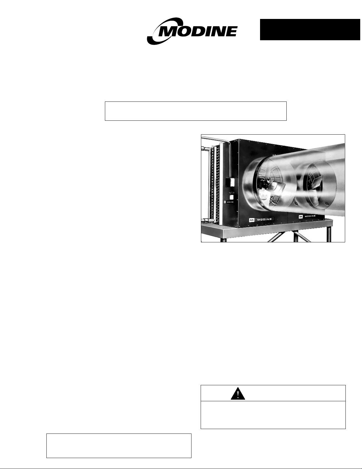
TTyyppee GGLLWW –– LLooww WWaatteerr TTeemmppeerraattuurree
GGrreeeennhhoouussee HHeeaattiinngg aanndd VVeennttiillaattiinngg UUnniittss
10-520.3
55HH7711775599 RReevv.. AA
IInnssppeeccttiioonn oonn AArrrriivvaall
1. Inspect unit upon arrival. In case of damage, report
immediately to transportation company and your local
Modine sales representative.
2. Check rating plate on unit and motor to verify that power
supply and motor specification requirements meet
available electric power at the point of installation.
3. Inspect unit received for conformance with description of
product ordered (including specifications where
applicable).
GGeenneerraall IInnffoorrmmaattiioonn
The heat exchanger is warranted for operation at hot water
pressures up to 300 lbs. per sq. in. gauge, and/or
temperatures up to 180°F.
SSppeecciiaall PPrreeccaauuttiioonnss
1. Disconnect power supply before making wiring
connections to prevent electrical shock and equipment
damage. All units must be wired strictly in accordance
with wiring diagram furnished with unit.
2. Units should not be installed in atmospheres where
corrosive fumes or sprays are present.
3. Units with power codes 01, 02, 03, 04, or 05 must not
be installed in potentially explosive or flammable
atmospheres.
4. Be sure no obstructions block air intake or air discharge
of unit.
LLooccaattiinngg GGLLWW UUnniittss
In locating units consider the general heating and ventilating
requirements of the greenhouse. Arranging units to simplify
piping and electrical supply systems should also be given
consideration.
IInnssttaalllliinngg GGLLWW UUnniittss
Because of their weight it is generally not feasible to
suspend a GLW unit from the roof supports of a
greenhouse. No provision for overhead suspension is
provided on GLW660S units. Brackets to facilitate overhead
suspension of model GLW330S units can be provided.
Normal practice is to place this GLW unit on a field
fabricated stand or platform that is fastened to the floor. Be
sure the means of support is adequate to suppor t the weight
of the unit. For proper operation the unit must be installed in
a level horizontal position.
MMOODDEELL GGLLWW666600SS
PPiippiinngg
Proper operation of the GLW greenhouse heating unit is
dependent on correct arrangement of unit piping.The points
listed below generally outline the areas which must be
considered. For more complete coverage on the subject of
piping, reference should be made to a reputable engineer’s
handbook or the ASHRAE guide.
1. Piping should be sized to properly handle the required
flow (GPM) of water.
2. In the absence of engineered data on an individual
application, piping the full size of the GLW unit
connections should be used. Supply and return runouts
must be the same size.The inlet is on the bottom. Inlet
and outlet connections are clearly marked on each GLW
unit.
3. Air must be continuously eliminated from the GLW unit
to secure rated performance and avoid premature coil
failure.
WWiirriinngg
All wiring must be done in accordance with the National
Electric Code and applicable local codes. In Canada, wiring
must conform to the Canadian Electric Code. Power supply
TTHHIISS MMAANNUUAALL IISS TTHHEE PPRROOPPEERRTTYY OOFF TTHHIISS OOWWNNEERR,, PPLLEEAASSEE
BBEE SSUURREE TTOO LLEEAAVVEE IITT WWIITTHH HHIIMM WWHHEENN YYOOUU LLEEAAVVEE TTHHEE JJOOBB..
As Modine Manufacturing Company has a continuous
product improvement program, it reserves the right to
change design and specifications without notice.
CAUTION
Disconnect power supply before making wiring
connections to prevent electrical shock and equipment
damage. All units must be wired strictly in accordance
with wiring diagram furnished with this unit.

22
IINNSSTTAALLLLAATTIIOONN//OOPPEERRAATTIIOONN
to these unit heaters must be protected by a fused disconnect
switch. It is recommended that all wiring be adequately
grounded.
WWiirriinngg
Electric wiring must be sized to carry the full load amp draw of
the motor, starter, and any controls that are used with the unit
heater.All units with power codes 04, 05, 08, or 09 (polyphase
motors) must be provided with suitable overcurrent protection
in circuit supplying heater at installation. Overcurrent
protectors should be sized based on motor current rating
shown on motor rating plate, and applicable national electric
code procedures.
All units are provided with electrical junction boxes.The
GLW660 may be field wired from either junction box.Any
damage to or failure of Modine units caused by incorrect
wiring of the units is not covered by Modine’s standard
warranty.See Page 4.
PPrriioorr ttoo OOppeerraattiioonn
1. Make sure fuses are installed in fused disconnect
switches.
2. Check all electrical connections to assure they are secure.
3. Check rigidity of unit mounting.Tighten all fasteners, if
necessary.
4. Inspect piping, strainers, fittings, etc.
IInniittiiaall SSttaarrtt--UUpp
1. Set thermostat to lowest position.
2. Turn on power supply to unit.
3. Open return gate valve, and then open supply gate valve
to unit.
4. Raise thermostat setting to desired position.
5. To insure proper sequence of operation, cycle unit on and
off a few times by raising and lowering thermostat setting.
6. Check for proper rotation of fan. All fans must rotate in a
counter-clockwise direction when viewed from the back of
the GLW unit.Do not attach polytubes to GLW unit until
proper rotation of fans is assured.
IInnssttaallllaattiioonn ooff PPoollyyeetthhyylleennee AAiirr
DDiissttrriibbuuttiinngg TTuubbee ((PPoollyyttuubbee))
TTuubbee IInnssttaallllaattiioonn
The polyethylene tube providing air distribution throughout the
greenhouse, is simply and directly connected to the heater
outlet transition with a gasket and a clamp.The clamp and
gasket are shipped attached to the unit.To install:
1. Remove clamp.
2. Thread a tube end through the clamp about 2 to 4 inches.
3. Orient the tube so that the distribution holes are in the
desired position.
4. Fit tube end clamp over the gasketed outlet transition and
secure clamp with a screwdriver.
5. Unroll tube to length desired and tie up opposite end.
6. Add air distribution holes as needed if polytube has been
shortened from standard length.
7. A minimum number of 100-3" diameter holes are required
for a 24" diameter polytube.
TTuubbee SSuussppeennssiioonn
For optimum air distribution the tube should be suspended
about 7 to 9 feet above the floor with the hoops and key rings
supplied.The tube must be hung without sharp bends or
twists.The hoops supplied are special straps of crosslaminated plastic for durability that include eyelets at each end
for clipping into key ring.The key rings, with strap and tube,
may be clipped onto either a long lead wire or an eyebolt in
the truss construction of the greenhouse. Because of the
variety of greenhouse constructions, no further provisions for
suspension are provided other than the hoops and key rings.
Recommended tube suspension with hoops is approximately
eight feet apart, which will be adequate for polytube weight
(12 lbs. per 100 feet) and sufficient to dampen out snapping
action when the tube is initially inflated. For wire suspension,
make sure the key rings are properly anchored, i.e., either
tied, taped, or looped into the wire to prevent shifting.While
the tube is inflated, stretch tube slightly and tie end to
greenhouse frame.This will reduce the chance of tube flutter
and increase the life of the tube.
RReeppllaacceemmeenntt PPaarrttss
All replacement parts and controls are proprietar y in that all
have been designed, tested, and approved for the particular
application to insure both physical and electrical fit and
performance. Any substitution of parts or controls not
approved by Modine will be at customer’s risk.
NNOOTTEE::
Modine Manufacturing Company reserves the right
to substitute parts of advanced design and to
change specifications or prices without advance
notice or without incurring obligations.
Replacement parts can be obtained by submitting the model
number, power code control code and serial number shown on
the rating plate attached to the unit, along with a description of
the part, to the Service Dept., Modine Manufacturing
Company, West Kingston, Rhode Island 02892.

33
PPEERRFFOORRMMAANNCCEE//DDIIMMEENNSSIIOONNSS
PPeerrffoorrmmaannccee DDaattee
Example of computing heating capacity in BTU/HR for model
GLW660S.
ETD is the difference between the entering water temperature
and the entering air temperature.
At 20 GPM with 100°F entering water temperature and 70°F
entering air temperature.
ETD = 100-70 = 30°F.
BTU/HR/°F of ETD from the curve = 4900
Heating capacity = 4900 x 30 = 147,000 BTU/HR.
Water pressure drip = 0.7 Ft. of water
Water temperature drop in °F =
DDiimmeennssiioonnss aanndd SSppeecciiffiiccaattiioonnss ––
MMooddeell GGLLWW666600SS,, GGLLWW333300SS
(All dimensions in inches)
HHoott WWaatteerr CCooiill
– 1/2" O.D.copper tubes; aluminum fins
– 1-1/2" MPT copper connections
– Frame - galvanized steel
– Maximum operating pressure - 300 PSI
– Maximum operating water temperature -
180°F
PPaanneellss aanndd TTrraannssiittiioonnss
– Galvanized steel
MMoottoorrss
– 1/2 H.P.; Single- or three-phase available (two
motors on GLW660S)
PPoollyyttuubbeess aarree AAvvaaiillaabbllee ffoorr SSppeecciiffiicc AApppplliiccaattiioonnss
–
24" diameter
AAiirr FFllooww
– GLW660S-7700 CFM;GLW330S-3850 CFM
WWeeiigghhtt
– GLW660S-380 Lbs.; GLW330S-200 Lbs.
BTU/HR
500 x GPM
6000
Model GLW660S
5000
4000
3000
Heating capacity
BTU/HR/ F of ETD
2000
1000
Model GLW330S
GLW660
GLW330
10
20 30 40 50
Water flow rate
gallons per minute
4.0
3.0
2.0
1.0
ft. of water
Water pressure drop

CCoommmmeerrcciiaall HHVVAACC&&RR DDiivviissiioonn
Modine Manufacturing Company
604 Liberty Lane
West Kingston, Rhode Island 02892
Phone: 1.800.828.4328 (HEAT)
FAX: 401.792.9041 (Service & Parts)
www.modine.com
3/02 - Litho in USA
MMooddiinnee wwaarrrraannttss iittss pprroodduuccttss ttoo bbee ffrreeee ffrroomm ddeeffeeccttss iinn mmaatteerriiaall aanndd
wwoorrkkmmaannsshhiipp,, eexxcclluussiivvee,, hhoowweevveerr,, ooff ffaaiilluurreess aattttrriibbuuttaabbllee ttoo tthhee uussee ooff
mmaatteerriiaallss ssuubbssttiittuutteedd uunnddeerr eemmeerrggeennccyy ccoonnddiittiioonnss ffoorr mmaatteerriiaallss nnoorrmmaallllyy
eemmppllooyyeedd.. TThhiiss wwaarrrraannttyy ccoovveerrss rreeppllaacceemmeenntt ooff aannyy ppaarrttss ffuurrnniisshheedd ffrroomm tthhee
ffaaccttoorryy ooff MMooddiinnee,, bbuutt ddooeess nnoott ccoovveerr llaabboorr ooff aannyy kkiinndd aanndd mmaatteerriiaallss nnoott
ffuurrnniisshheedd bbyy MMooddiinnee,, oorr aannyy cchhaarrggeess ffoorr aannyy ssuucchh llaabboorr oorr mmaatteerriiaallss,, wwhheetthheerr
ssuucchh llaabboorr,, mmaatteerriiaallss oorr cchhaarrggeess tthheerreeoonn aarree dduuee ttoo rreeppllaacceemmeenntt ooff ppaarrttss,,
aaddjjuussttmmeennttss,, rreeppaaiirrss,, oorr aannyy ootthheerr wwoorrkk ddoonnee.. TThhiiss wwaarrrraannttyy ddooeess nnoott aappppllyy ttoo
aannyy eeqquuiippmmeenntt wwhhiicchh sshhaallll hhaavvee bbeeeenn rreeppaaiirreedd oorr aalltteerreedd oouuttssiiddee tthhee ffaaccttoorryy
ooff MMooddiinnee iinn aannyy wwaayy ssoo aass,, iinn tthhee jjuuddggeemmeenntt ooff MMooddiinnee,, ttoo aaffffeecctt iittss ssttaabbiilliittyy,,
nnoorr wwhhiicchh hhaass bbeeeenn ssuubbjjeecctteedd ttoo mmiissuussee,, nneegglliiggeennccee,, oorr ooppeerraattiinngg ccoonnddiittiioonnss
iinn eexxcceessss ooff tthhoossee ffoorr wwhhiicchh ssuucchh eeqquuiippmmeenntt wwaass ddeessiiggnneedd..
BUYER AGREES THAT MODINE’S WARRANTY OF ITS PRODUCTS TO BE
FREE FROM DEFECTS IN MATERIAL AND WORKMANSHIP, AS LIMITED
HEREIN, SHALL BE IN LIEU OF AND EXCLUSIVE OF ALL OTHER
WARRANTIES, EITHER EXPRESS OR IMPLIED, WHETHER ARISING
FROM LAW, COURSE OF DEALING, USAGE OF TRADE, OR OTHERWISE.
TTHHEERREE AARREE NNOO OOTTHHEERR WWAARRRRAANNTTIIEESS,, IINNCCLLUUDDIINNGG WWAARRRRAANNTTYY OOFF
MMEERRCCHHAANNTTAABBIILLIITTYY OORR FFIITTNNEESSSS FFOORR PPUURRPPOOSSEE,, WWHHIICCHH EEXXTTEENNDD
BBEEYYOONNDD TTHHEE DDEESSCCRRIIPPTTIIOONN OONN TTHHEE FFAACCEE HHEERREEOOFF..
BUYER’S REMEDY FOR BREACH OF WARRANTY, EXCLUSIVE OF ALL
OTHER REMEDIES PROVIDED BY LAW, IS LIMITED TO REPAIR OR
REPLACEMENT AT THE FACTORY OF MODINE, ANY PART OF PARTS
WHICH SHALL, WITHIN ONE YEAR FROM DATE OF FIRST BENEFICIAL
USE BY BUYER OR ANY OTHER USER, WITHIN ONE YEAR FROM DATE
OF RESALE BY BUYER IN ANY UNCHANGED CONDITION, OR WITHIN
EIGHTEEN MONTHS FROM DATE OF SHIPMENT FROM MODINE,
WHICHEVER OCCURS FIRST, BE RETURNED THERETO WITH
TRANSPORTATION CHARGES PREPAID AND WHICH THE EXAMINATION
OF MODINE SHALL DISCLOSE TO HAVE BEEN DEFECTIVE;EXCEPT
THAT WHEN THE PRODUCT IS TO BE USED BY BUYER AS A
COMPONENT PART OF EQUIPMENT MANUFACTURED BY BUYER,
BUYER’S REMEDY FOR BREACH, AS LIMITED HEREIN, SHALL BE
LIMITED TO ONE YEAR FROM DATE OF SHIPMENT FROM MODINE.
BUYER AGREES THAT IN NO EVENT WILL MODINE BE LIABLE FOR
COSTS OF PROCESSING, LOST PROFITS, INJURY TO GOODWILL, OR
ANY OTHER CONSEQUENTIAL OR INCIDENTAL DAMAGES OF ANY KIND
RESULTING FROM THE ORDER OR USE OF ITS PRODUCT, WHETHER
ARISING FROM BREACH OF WARRANTY, NONCONFORMITY TO
ORDERED SPECIFICATIONS, DELAY IN DELIVERY, OR ANY LOSS
SUSTAINED BY THE BUYER.
Modine warrants Polytube (Air Distribution Tubes) for a period of three
months from date of first beneficial use by buyer or any other user, within
three months from date of resale by Buyer in any unchanged condition, or
within six months from date of shipment from Modine, whichever occurs first.
IInnssppeecctt RReegguullaarrllyy
Under average conditions, it is recommended that GLW
units be inspected before every heating season. Check for
dirty, clogged condensers, excessive vibration and loose
connections.
MMoottoorrss
AA.. CClleeaanniinngg
Remove grease and dirt on motor during each
inspection or lubrication, or whenever condensers are
cleaned, whichever is sooner.
BB.. LLuubbrriiccaattiioonn
1. Lubricate motor according to manufacturer’s
instructions located on the motor.
2. When no motor oiling instructions are on the motor,
oil the motor every two thousand hours of operation
with SAE20 motor oil for units in normal
applications. Adjust oiling according to usage and
atmosphere.
3. Some motors do not have oil fittings.These motors
are lubricated for long life and do not require further
lubrication.
CC.. OOvveerrllooaadd PPrrootteeccttiioonn
A change in line voltage higher or lower than motor
nameplate rating may cause overheating and serious
motor damage. Check voltage conditions.A separate
manual starter with thermal overload protection device is
recommended for those units that do not have motors
with built-in overload protection.
CCoonnddeennsseerrss
AA.. CClleeaanniinngg
Clean condenser at least once a year; more often under
unfavorable conditions.Unless condenser is kept
reasonably free of dirt, lint and grease, its original
heating capacity will be reduced…possibly to a serious
degree, and motor damage may result.
BB.. IInntteerrnnaall CCoorrrroossiioonn SSaaffeegguuaarrddss
Provide controlled water treatment…Contact your
compound supplier for proper usage or the services of a
water treatment laboratory.
Periodic internal flushing of the coils is recommended in
areas where water supply is suspected of causing scale.
CCaassiinnggss
AA.. CClleeaanniinngg
Periodic cleaning of casings is recommended to remove
dirt, grease and corrosive substances that may injure
finish.
BB.. GGeenneerraall IInnssppeeccttiioonn
Tighten fan guard and motor bracket, Check fan for
proper clearance, free rotation and firm connection to
shaft.
When servicing is complete, tag unit to indicate date of
inspection, lubrication and cleaning.
MMAAIINNTTEENNAANNCCEE
WARNING
Using inorganic or mineral acids such as muriatic
(hydrochloric) acid, even though inhibited, may lead to
severe damage, including corrosion and leakage.
WWAARRRRAANNTTYY
© Modine Manufacturing Company 2002
 Loading...