

Modine Manufacturing PDE, G31, G20 Service Manual
installation and service manual
gas-fired unit heaters
models PDE
G20, G31
6-592
55HH7755004477AA
CCoonntteennttss
Pages
Inspection on arrival..............................................................1
Special precautions ..............................................................2
General introduction .............................................................3
Technical data....................................................................3-4
Installation .........................................................................4-6
Positioning heater..............................................................4
Ventilation..........................................................................5
Unit suspension.................................................................5
Flue system....................................................................5-6
Piping ................................................................................6
Gas supply........................................................................6
Electrical supply................................................................6
Commissioning .....................................................................7
Servicing...............................................................................8
Wiring Diagram.....................................................................9
Major Component Location ..................................................9
Replacement of parts .........................................................10
Fault finding........................................................................11
Spare parts list ..............................................................11-12
WARNING
IImmpprrooppeerr iinnssttaallllaattiioonn,, aaddjjuussttmmeenntt,,
aalltteerraattiioonn,, sseerrvviiccee oorr mmaaiinntteennaannccee ccaann ccaauussee
pprrooppeerrttyy ddaammaaggee,, iinnjjuurryy oorr ddeeaatthh,, aanndd ccoouulldd
ccaauussee eexxppoossuurree ttoo ssuubbssttaanncceess wwhhiicchh hhaavvee
bbeeeenn ddeetteerrmmiinneedd bbyy vvaarriioouuss aaggeenncciieess ttoo
ccaauussee ccaanncceerr,, bbiirrtthh ddeeffeeccttss oorr ootthheerr
rreepprroodduuccttiivvee hhaarrmm.. RReeaadd tthhee iinnssttaallllaattiioonn,,
ooppeerraattiinngg aanndd mmaaiinntteennaannccee iinnssttrruuccttiioonnss
tthhoorroouugghhllyy bbeeffoorree iinnssttaalllliinngg oorr sseerrvviicciinngg tthhiiss
eeqquuiippmmeenntt..
FFOORR YYOOUURR SSAAFFEETTYY
IIff yyoouu ssmmeellll ggaass::
11.. OOppeenn wwiinnddoowwss
22.. DDoonn''tt ttoouucchh eelleeccttrriiccaall sswwiittcchheess..
33.. EExxttiinngguuiisshh aannyy ooppeenn ffllaammee..
44.. IImmmmeeddiiaatteellyy ccaallll yyoouurr ggaass ssuupppplliieerr..
FFOORR YYOOUURR SSAAFFEETTYY
TThhee uussee aanndd ssttoorraaggee ooff ggaassoolliinnee oorr ootthheerr
ffllaammmmaabbllee vvaappoouurrss aanndd lliiqquuiiddss iinn ooppeenn
ccoonnttaaiinneerrss iinn tthhee vviicciinniittyy ooff tthhiiss aapppplliiaannccee iiss
hhaazzaarrddoouuss..
THIS MANUAL IS THE PROPERTY OF THE OWNER.
PLEASE BE SURE TO LEAVE IT WITH THE OWNER WHEN
YOU LEAVE THE JOB.
!
TToo pprreevveenntt pprreemmaattuurree hheeaatt eexxcchhaannggeerr ffaaiilluurree
ddoo nnoott iinnssttaallll AANNYY ggaass ffiirreedd uunniittss iinn aarreeaass
wwhheerree cchhlloorriinnaatteedd,, hhaallooggeennaatteedd oorr aacciidd vvaappoouurrss
aarree pprreesseenntt iinn tthhee aattmmoosspphheerree..
IInnssppeeccttiioonn oonn AArrrriivvaall
1. Inspect unit upon arrival. In case of damage, report
immediately to transportation company , and y our local sales
representative.
2.
Inspect unit received for conformance with description of
product ordered.
IMPORTANT
TThhee uussee ooff tthhiiss mmaannuuaall iiss ssppeecciiffiiccaallllyy iinntteennddeedd
ffoorr aa qquuaalliiffiieedd iinnssttaallllaattiioonn aanndd sseerrvviiccee aaggeennccyy..
AAllll iinnssttaallllaattiioonn aanndd sseerrvviiccee ooff tthheessee uunniittss mmuusstt
bbee ppeerrffoorrmmeedd bbyy aa qquuaalliiffiieedd iinnssttaallllaattiioonn aanndd
sseerrvviiccee aaggeennccyy..
August, 1999
0120

22
TTHHEE IINNSSTTAALLLLAATTIIOONN AANNDD MMAAIINNTTEENNAANNCCEE IINNSSTTRRUUCCTTIIOONNSS
IINN TTHHIISS MMAANNUUAALL MMUUSSTT BBEE FFOOLLLLOOWWEEDD TTOO EENNSSUURREE SSAAFFEE,,
EEFFFFIICCIIEENNTT AANNDD TTRROOUUBBLLEE-FFRREEEE OOPPEERRAATTIIOONN.. IINN
AADDDDIITTIIOONN,, PPAARRTTIICCUULLAARR CCAARREE MMUUSSTT BBEE EEXXEERRCCIISSEEDD
RREEGGAARRDDIINNGG TTHHEE SSPPEECCIIAALL PPRREECCAAUUTTIIOONNSS LLIISSTTEEDD BBEELLOOWW..
FFAAIILLUURREE TTOO PPRROOPPEERRLLYY AADDDDRREESSSS TTHHEESSEE CCRRIITTIICCAALL
AARREEAASS CCOOUULLDD RREESSUULLTT IINN PPRROOPPEERRTTYY DDAAMMAAGGEE OORR LLOOSSSS,,
PPEERRSSOONNAALL IINNJJUURRYY,, OORR DDEEAATTHH..
1. Any power supply must be disconnected before making
wiring connections to prevent electrical shock and
equipment damage. All units must be wired strictly in
accordance with the wiring diagram (see Fig. 6 page 9).
2. The gas supply must be turned off before commencing
installation of the heaters. An isolating union gas cock or
union and isolating gas cock
MMUUSSTT
be fitted before the inlet
to the gas valve to allow replacement of parts.
3. The gas supply pressure to the unit heater controls must
never exceed 45mbar.
When leak testing the gas supply system, the unit, and its
combination gas control, must be isolated during any
pressure testing in excess of 45mbar. The unit should be
isolated from the gas supply system by closing the manual
shutoff valve.
4. Start-up and adjustment procedures should be performed
by a qualified engineer.The gas inlet pressure should be
checked upstream of the combination gas control.The inlet
pressure should be at least 20mbar on natural gas or 37mbar
on propane.Purging of gas piping should be perf ormed as
described in IM2. Supply pressure and setting pressure must
be checked with heater in operation when making final
adjustments.
5. All units must be flued to outside.
6. The units
MMUUSSTT NNOOTT bbee
installed in potentially explosive or
flammable atmospheres laden with grain dust, sawdust or
similar airborne materials.
7. Installation of units in high humidity or salt water
atmospheres should be avoided as this will cause
accelerated corrosion resulting in a reduction of the normal
life span of the units.
8. To prevent premature heat exchanger failure do not locate
AANNYY
gas fired unit in areas where chlorinated, halogenated
or acid vapours are present in the atmosphere.
9. Do not install units in extremely draughty locations.
Draughts can cause burner flames to impinge on the heat
exchanger thereby shortening its life.Separation between
units should be maintained to avoid discharge from one unit
entering the inlet of another.
10. Do not install units in tightly sealed rooms or small
compartments without provision for adequate combustion
air and venting. Combustion air must have access to the
space through a minimum of two permanent openings in
the enclosure, one near the bottom and the other near the
top.They should provide a free area of at least the values
given in Section 2.2 ‘Ventilation’.
11. Do not install units outdoors
12. For all sizes, required minimum clearance to combustible
materials from the bottom of the unit is 300mm (however
see page 2 section 16 which may require greater
clearances for servicing) and from the sides 450mm. For
PDE units sizes 30-50 minimum clearance from the top is
25mm and from the flue collar 50mm; for PDE units sizes
75-300 minimum clearance from the top is 50mm and from
the flue collar is 75mm; for PDE unit 350 minimum
clearance from the top is 75mm and from the flue collar is
100mm, for PDE unit 400 minimum clearance from the top
is 100mm and from the flue collar is 125mm.
13. At least 150mm clearance at the sides and 300mm
clearance at rear (or 150mm beyond end of motor at rear of
unit, whichever is greater) must be allowed to provide
sufficient air for combustion and correct operation of the
fan.However see page 2 section 12 for clearances to
combustible material.
14. The minimum distance required from combustible materials
is based on the combustible material surface not exceeding
70°C.Clearance from the top of the unit may be required to
be greater than 150mm if heat damage, other than fire,
may occur to materials above the unit heater at the
temperature described.
15. PDE unit heaters are designed for use in heating
applications with ambient temperatures between 0°C
and 32°C.If an application exists where ambient
temperatures can be expected to fall outside of this range,
contact your local sales representative for
recommendations.
16. Clearance must be provided for opening hinged bottom for
servicing. See Figure 1. Do not stand unit on its base.
17. To ensure that flames do not impinge on heat exchanger
surfaces, the unit must be suspended in a ver tical and level
position. Failure to suspend a unit properly may shorten its
life.
18. The unit heater must not be lifted by its gas controls or gas
manifold.
19. Ensure there are no obstructions which block air intake and
discharge of the unit heater.
20. Do not attach duct work or air filters to any PDE model unit
heaters.
21. In aircraft hangars, the bottom of the unit must be at least
3m from the highest surface of the wings or engine
enclosures of the highest aircraft housed in the hangar and
the installation must be in accordance with the
requirements of the enforcing authority.
22. In garages or other sections of aircraft hangars such as
offices and shops which communicate with areas used for
servicing or storage, the bottom of the unit must be at least
1.8m above the floor.
23. The piping, electrical, ventilation and flueing instructions in
this manual should be carefully read before commencing
installation.
24. All literature shipped with the unit should be kept for future
use for servicing or service diagnosis. None of the literature
shipped with the unit should be discarded.
25. Only approved service replacement parts should be used
when servicing or repairing these unit heaters. A complete
replacement parts list may be obtained by contacting your
appliance supplier.The data plate on the unit gives the unit
model number, serial number and company address. Any
substitution of non-approved parts or controls is at the
owners risk and may invalidate the EC Certification.
26. Always turn off the gas supply at the gas cock and
disconnect the electricity supply to the appliance before
servicing or replacing any components.
27. These unit heaters will normally be controlled by a room
thermostat. Harry Taylor have available a proportional
temperature controller (PTC-1) which can be used to
provide this control. If a room thermostat is to be used
contact Harry Taylor for details of suitable models.
IINNSSTTAALLLLAATTIIOONN
SSPPEECCIIAALL PPRREECCAAUUTTIIOONNSS
33
These instructions are for the PDE unit set up as a Category
I
2H
heater to use natural gas (G20) at a nominal supply
pressure of 20mbar.This is one of its many CE certified forms.
Information on the PDE unit set up as a Catergory I
3+
heater to
use propane (G31) at a nominal suppy pressure of 37mbar,
another certified form, is given in Table 4, page 12.
HHeeaatteerrss
mmuusstt nnoott uussee ggaasseess ootthheerr tthhaann tthhoossee ffoorr wwhhiicchh tthheeyy wweerree
ddeessiiggnneedd aanndd bbuuiilltt..
These instructions should be read thoroughly before
commencing installation of the appliance.
It is the law that all gas appliances are installed by competent
persons, e.g. CORGI Registered, in accordance with the Gas
Safety (Installation and Use) Regulations 1984 (As Amended).
Failure to install the appliance correctly could lead to
prosecution and it is therefore in your interest, and that of
safety, to ensure the law is complied with.
The installation of the appliance must be in accordance with
the current I.E.E. Regulations (BS 7671), and relevant
requirements of the local gas region, local authority, British
Standard Codes of Practice and Building Regulations.
SSeeee aallssoo::
BS 6891 Installation of Low Pressure Pipework.
BS 6230 Installation of Gas Fired Forced Convection Air
Heaters for Commercial and Industrial Space Heating.
BBrriittiisshh GGaass PPuubblliiccaattiioonnss::
IM 2 Purging Procedures of Non-Domestic Gas Boilers.
IM 5 Soundness Testing Procedures for Non-Domestic Gas
Installations.
IM 11 Flues for Commercial and Industrial Gas Fired Boilers
and Air Heaters.
IM 16 Guidance Notes for the Installation of Gas Pipework.
MMOODDIINNEE GGAASS FFIIRREEDD UUNNIITT HHEEAATTEERRSS PPDDEE MMOODDEELLSS
GGEENNEERRAALL IINNTTRROODDUUCCTTIIOONN
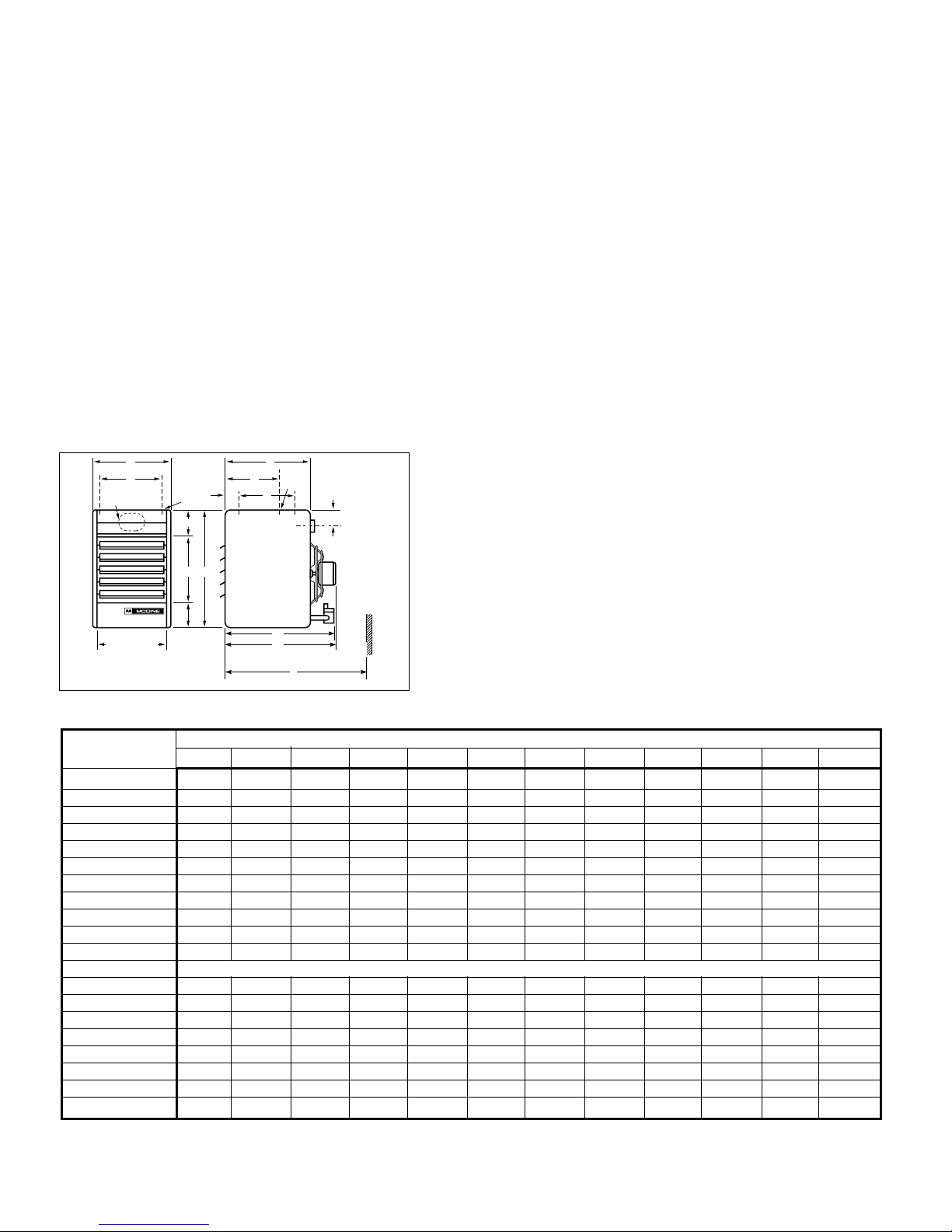
TTAABBLLEE 11..TTEECCHHNNIICCAALL DDAATTAA
A
H
D (OPENING)
BB
E
AA
B
K
W
X
F
C
K
G
L - Approx
MIN. DISTANCE
TO WALL IS L + 6"
J VENT PIPE
EE
(MIN. DISTANCE TO WALL)
L
LL
DDiimmeennssiioonnss ((mmmm))
DDiimmeennssiioonn MMooddeell NNuummbbeerr -PPDDEE
SSyymmbbooll 3300 5500 7755 110000 112255 115500 117755 220000 225500 330000 335500 440000
AA
327 438 438 489 489 533 597 651 651 727 854 1,016
BB
616 616 730 730 895 895 895 1,022 1,022 1,022 1,022 1,022
CC
375 375 508 508 559 559 559 635 635 635 635 635
DD
265 376 376 427 427 472 535 589 589 665 792 953
EE
330 330 406 406 508 508 508 610 610 610 610 610
FF
235 235 279 279 305 305 305 343 343 356 ––
GG
51 51 70 70 92 92 92 111 111 111 108 108
HH
235 346 346 397 397 448 505 559 559 635 762 924
AAAA
127 127 159 159 203 203 203 229 229 229 229 229
BBBB
159 159 165 165 184 184 184 184 184 184 184 184
JJ ((IInncchheess))
3" 4" 5" 6" 6" 7" 7" 7" 8" 9" 10" 10"
KK
11
M10
GGaass CCoonnnn.. ""
1/2 1/2 1/2 1/2 1/2 1/2 1/2 1/2 1/2 3/4 3/4 3/4
WW
––––––– –––127 127
XX
––––––– –––406 406
LL
22
718 718 914 914 927 943 943 1,038 1,041 1,073 1,073 1,200
LLLL
448 457 590 599 650 669 699 775 775 797 797 797
EEEE
565 565 737 737 775 775 775 835 835 835 835 835
FFaann DDiiaammeetteerr
228 305 305 348 348 408 458 508 508 560 560 650
AApppprrooxx.. WWeeiigghhtt ((kkgg))
26.4 32.7 46.4 52.7 69.1 73.6 76.8 105 105 118.6 150 186.4
1
PDE30 to PDE300 inclusive - 2 holes (and the level hanging adjustment feature). PDE350 and PDE400 - 4 holes.
2
Dimension equals overall plus 150mm.
NNOOTTEE:: NNOOTT AALLLL MMOODDEELLSS AARREE AAVVAAIILLAABBLLEE IINN TTHHEE UUKK.. CCHHEECCKK WWIITTHH YYOOUURR SSUUPPPPLLIIEERR..
DDIIMMEENNSSIIOONNSS PPEERRFFOORRMMAANNCCEE —— PPDDEE
44
IINNSSTTAALLLLAATTIIOONN
22..11 PPoossiittiioonniinngg UUnniitt HHeeaatteerrss
When siting units, consider general spaceheating requirements,
availability of gas, and proximity to flue locations. Unit heaters
should be positioned so heated air streams wipe exposed walls
without blowing directly against them.In multiple unit
installations, arrange units so that each supports the air stream
from another, setting up circulatory air movement in the area,
but maintain separation between units so discharge from one
unit will not be directed into the inlet of another.In buildings
exposed to prevailing winds, a large portion of the heated air
should be directed along the windward wall.Avoid interference
to air streams as much as possible.Mounting height (measured
from bottom of unit) at which unit heaters are installed is critical.
Maximum mounting heights are listed in the Table 1 on page 3.
The maximum mounting height for any unit is that height above
which the unit will not deliver heated air to the floor. The
maximum mounting heights must not be exceeded in order to
ensure maximum comfort. PDE unit heaters are designed for
use in heating applications with ambient temperatures between
O°C and 32°C.If an application exists where ambient
temperatures can be expected to fall outside this range, contact
your local sales representative for recommendations.
CAUTION
Units must not be installed in potentially explosive,
flammable, or corrosive atmosphere. To prevent premature
heat exchanger failure do not locate ANY gas fired unit in
areas where chlorinated, halogenated or acid vapours are
present in the atmosphere.
!
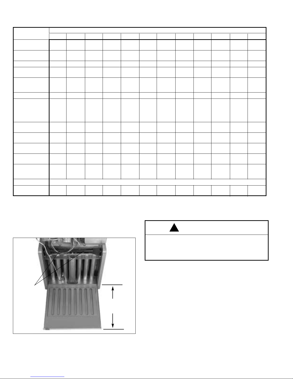
FFiigguurree 11
HHiinnggeedd BBaassee ffoorr SSeerrvviicciinngg
(See Dimension "C", page 3)
WING SCREWS
THAT SECURE
HINGED
BOTTOM
THIS IS
DIMENSION C,
SEE PAGE 3
PPeerrffoorrmmaannccee —— nnaattuurraall ggaass oonnllyy.. SSeeee ppaaggee 1122 ffoorr pprrooppaannee ddeettaaiillss..
*
Based on natural gas - typical calorific value 37.78 MJ/M3.
**
At 18°C ambient and unit fired at full-rated input. Mounting height as measured from bottom of unit.
NNOOTTEE:: NNOOTT AALLLL MMOODDEELLSS AARREE AAVVAAIILLAABBLLEE IINN TTHHEE UUKK.. CCHHEECCKK WWIITTHH YYOOUURR SSUUPPPPLLIIEERR..
TTAABBLLEE 22
MMooddeell NNuummbbeerr-PPDDEE
3300 5500 7755 110000 112255 115500 117755 220000 225500 330000 335500 440000
HHeeaatt IInnppuutt
((ggrroossss)) kkWW**
8.8 14.7 22.0 29.3 36.6 44.0 51.3 58.6 73.3 87.9 102.6 117.2
HHeeaatt IInnppuutt
((nneett)) kkWW**
7.9 13.2 19.8 26.4 32.6 39.6 46.2 52.7 66.0 79.1 92.3 105.5
OOuuttppuutt kkWW**
7.0 11.7 17.6 23.4 29.3 35.1 41.0 46.9 58.6 70.3 82.0 93.8
BBuurrnneerr sseett..
7.0 6.7 6.8 6.7 6.5 6.1 5.7 7.1 5.5 7.2 6.5 6.4
pprreessss.. mmbbaarr
IInnjjeeccttoorr - NNoo..
111222333456
DDiiaamm.. mmmm
2.71 3.45 4.30 3.45 3.91 4.30 3.86 3.86 4.7 4.22 4.22 4.09
MMaarrkkiinngg
36 29 18 29 23 18 24 24 13 19 19 20
GGaass rraattee mm33//hh
0.82 1.36 2.04 2.72 3.39 4.08 4.76 5.43 6.8 8.15 9.51 10.87
AApppprrooxx.. fflluuee
9 14 21 29 36 43 50 57 71 86 100 114
ggaass vvooll.. iinn
sseeccoonnddaarryy fflluuee**
33..77%% CCOO22&&
110000°°CC 11//sseecc
AAiirr ffllooww
0.21 0.35 0.51 0.69 0.87 1.03 1.20 1.36 1.75 2.10 2.34 2.66
mm33//sseecc
OOuuttlleett vveelloocciittyy
2.6 3.2 3.7 4.3 4.4 4.7 4.8 4.1 5.3 5.7 5.6 5.3
mm//sseecc
AAiirr TTeemmpp rriissee
27 27 28 27 27 28 28 28 27 27 28 28
°°CC
MMoouunnttiinngg hhtt..
2.1 2.7 3.7 4.3 4.3 4.9 5.2 4.6 5.8 6.4 6.1 6.7
((mmaaxx)) mm
HHeeaatt tthhrrooww
7.6 10.1 12.5 14.9 15.5 16.8 18.0 15.5 20.4 22.6 21.9 23.2
((aatt mmaaxx mmoouunntt.. hhtt..))
mm****
PPoowweerr ssuuppppllyy
230V 50Hz
PPoowweerr uussee
125 150 200 225 400 450 450 400 750 850 950 1,200
((wwaattttss))
 Loading...